Table of Contents
Advertisement
D
i
r
D
i
r
PR5300 • PR5310 • PR5350 • PR53LE
TEAMNisca, A Division of Kanematsu USA, Inc. 100 Randolph Road, Somerset, NJ 08873
Copyright © 2005, Kanematsu USA, Inc. All rights reserved.
TEAMNisca® and the TEAMNisca® logo are a registered trademark of Kanematsu USA, Inc. Microsoft® and
Windows® are U.S. trademarks of Microsoft Corporation. Names of products mentioned herein are used for
identification purposes only and may be trademarks and/or trademarks of their respective companies.
e
c
t
C
a
e
c
t
C
a
U
s
e
r
'
s
U
s
e
r
'
s
Nisca Series
r
d
P
r
i
r
d
P
r
i
G
u
i
d
e
G
u
i
d
e
n
t
e
r
n
t
e
r
Advertisement
Table of Contents
Troubleshooting

Related Manuals for Nisca PR5350


Summary of Contents for Nisca PR5350
- Page 1 ’ ’ Nisca Series PR5300 • PR5310 • PR5350 • PR53LE TEAMNisca, A Division of Kanematsu USA, Inc. 100 Randolph Road, Somerset, NJ 08873 Copyright © 2005, Kanematsu USA, Inc. All rights reserved. TEAMNisca® and the TEAMNisca® logo are a registered trademark of Kanematsu USA, Inc. Microsoft® and Windows®...
-
Page 3: Table Of Contents
Table of Contents Chapter 1: Introduction 1.2 Welcome! ..........................1 1.3 About This User’s Guide ....................1 1.4 General Site Requirements ....................2 1.5 Important Safety Instructions ....................2 1.5.1 Electrical Requirements .....................3 1.5.2 Physical Requirements ....................3 1.5.3 Environmental Requirements ..................3 Chapter 2: Getting Started 2.1 Printer Features ........................4 2.1.1 Front of the Printer ....................4 2.1.2 Rear of the Printer .....................5... - Page 4 Appendix B: Printer Configuration ................39 Appendix C: User Mode Menu Map C-1 PR5300/PR5310 User Mode Menu Map .................41 C-2 PR5350 User Mode Menu Map ..................43 C-3 PR53LE User Mode Menu Map ..................45 Appendix D: Parts Replacement D-1 Replacing the Input Rollers .....................47 D-2 Replacing the Print Head ....................48...
-
Page 5: Chapter 1: Introduction
C H A P T E R Introduction 1.2 Welcome! Congratulations on your purchase of the Nisca PR53xx Series Direct Card Printer. The printer gives you brilliant images using these features: Full color edge to edge 300 dpi dye sublimation printing technology... -
Page 6: General Site Requirements
Note This note symbol means reader take note. Notes contain important information and helpful suggestions about your printer. 1.4 General Site Requirements When choosing a site for the PR53xx series printer, consider the following recommendations: Select a site that is out of direct sunlight to prevent deformation of the plastic housing and discoloration of the cards. -
Page 7: Electrical Requirements
• The printer does not operate normally or exhibits a distinct change in performance. 1.5.1 Electrical Requirements The PR53xx series printer requires the following electrical specifications for optimal performance: 100-240 VAC at 50/60 Hz. The printer is auto-switching to power within this range. Single phase, 3-wire grounded receptacle. -
Page 8: Chapter 2: Getting Started
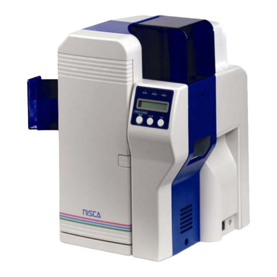
C H A P T E R Getting Started Note This user’s guide explains the operation of the PR5300, PR5310, PR5350 and PR53LE. Where necessary, the areas that apply only to certain printer models will be specified. 2.1 Printer Features Figure 2-1: Printer features 2.1.1 Front of the Printer... -
Page 9: Rear Of The Printer
Supplies power to the printer. E. RS232C Interface Interface for RFID encoding and reading modules. Connect using a D-Sub 9 pin female (DB-9) to a D-Sub 9 pin female. Cable not included. Interface is only available on models PR5310 and PR5350. -
Page 10: Lcd Panel
2.1.3 LCD Panel Figure 2-3: Printer LCD panel 2.1.4 LCD Operation ITEM DESCRIPTION MODE FUNCTION LCD Panel Normal Displays the printer’s status. User Displays the selected menu or values. Ready LED Green light indicates printer is ready and will accept data. Error LED Indicates an error has occurred. -
Page 11: Front Access Panel
2.1.5 Front Access Panel Figure 2-4: Front access panel A. Input Roller Module Removes dust particles from the top and bottom of the card as it feeds into the printer. B. Green Retaining Lever Prevents the ribbon cartridge from being removed. C. - Page 12 Card Weight Eject Card Box Ribbon (Refer to Chapter 2.3: Loading The Ribbon) Ribbon Cartridge Printer Driver CD Warranty Registration Card If any items are missing, please contact your authorized reseller. Note Keep all packing material in case you need to move or re-ship the printer 4.
-
Page 13: Loading The Ribbon
YMCK0K2 Note IMPORTANT! Nisca card printers require special ribbons to function properly. For this reason, use only genuine Nisca ribbons from Nisca authorized resellers. Use of non Nisca ribbons may void the warranty and reduce the print quality and durability. - Page 14 Caution IMPORTANT! To prevent damage to the print head, you must press the Ribbon Change button BEFORE removing the ribbon cartridge. Refer to figure 2-3: Printer LCD panel. Initially, the print head has been retracted at the factory for shipment so you do not have to press the Ribbon Change button for initial setup.
- Page 15 4. Remove the tape and pull the released ribbon towards the take up bobbin. Attach the tape to the bobbin making sure the ribbon is centered on the bobbin. Figure 2-10: Remove tape 5. Advance the takeup bobbin 2-3 turns to verify that the ribbon is properly seated on the bobbin and all slack has been removed from the ribbon.
-
Page 16: Connecting The Printer
2.4 Connecting The Printer This section describes how to connect the printer to a power source and to a PC that runs the printer driver. Depending on the model you purchased, it can be connected either by SCSI, Parallel, or USB: Parallel SCSI Figure 2-12: Printer connection types... -
Page 17: Parallel Connection
3. You can set the ID number in the printer by accessing the User Mode Menu. Press and hold the Menu button on the LCD panel until it displays “User Mode”. 4. Press the EXE button several times until the SCSI ID sub menu is displayed. Press the Menu button to enter this menu and select the appropriate ID number using the EXE button. -
Page 18: Usb Connection
2. Connect the micro centronics connector to the printer’s parallel port, and snap the fastening clips into place. Figure 2-15: Parallel port 3. Connect the other side of the cable to the parallel connector on the back of the computer. 4. -
Page 19: Loading Cards
3. Plug the other end of the USB cable into the computer. 4. Insert the power cord into the power receptacle on the rear of the printer. Plug the other end into an available wall outlet. 2.5 Loading Cards Before you begin printing, you must load blank cards into the printer’s card feeder. You may load cards while the printer’s power is either on or off. -
Page 20: Card Thickness Adjustment
2.6 Card Thickness Adjustment When loading cards that vary from the standard size, it is necessary to make a simple adjustment to the printer. To adjust the card size, follow these steps: 1. Open the card feeder door and remove cards. 2. -
Page 21: Turning On The Printer
2.7 Turning on the Printer Before installing the printer driver and before using the printer, follow these steps to power on the printer. 1. The computer connected to the printer should be turned off. 2. Make sure cards and printer ribbon have been loaded. 3. -
Page 22: Functions Of The User Mode
2.8.3 Functions of the User Mode Card Count Indicates the current card count and is used to monitor card production. Pressing the Clear key resets the value to 0. Total Count Indicates the total number of cards printed and cannot be reset. This value helps give the operator a measure of the printer’s overall work cycle. - Page 23 IC-R/W Error Mode Controls the display of error messages on the LCD panel. EXE Key Print Set to on to have data in the memory printed. Print Retry Set to on to have card with error re-outputted. Parallel Print Set to on to process multiple cards simultaneously. Card Eject Face Select which side of the card to eject.
-
Page 24: Chapter 3: Maintenance
C H A P T E R Maintenance Your Nisca PR53xx series printer is built to require a minimum amount of maintenance. Nevertheless, there are a few procedures you need to perform on a regular basis or as needed to ensure maximum performance. - Page 25 1. Enter User Mode by pressing and holding the Menu button for 3 seconds. Figure 3-1: Entering User Mode 2. Press EXE and then use the Menu button to navigate to the Cleaning sub-menu. See User Mode Menu Map in Appendix C for navigation assistance. 3.
-
Page 26: Manual Cleaning
3.2 Manual Cleaning As you use your printer, dust and other particles may accumulate inside the printer before you actually need to replace the ribbon. To maintain a consistent print quality, manual cleaning procedures should be performed periodically. The following identifies areas needed for manual cleaning. - Page 27 1. Open the front access panel by depressing the release button. Figure 3-5: Open front access panel 2. Grasp the input roller module tab and pull it out of the printer. Figure 3-6: Grasp input roller 3. Clean the rollers with an alcohol cotton swab in the direction pictured. Figure 3-7: Cleaning the rollers 4.
-
Page 28: Cleaning The Flip/Turn Transport Rollers
3.4 Cleaning the Flip/Turn Transport Rollers 1. Power off the printer and remove the power cord. 2. Remove the phillips screw on the left side of the printer to open the print unit door. Open the top cover and manually rotate the flip/turn transport roller 180° by moving the unit counter-clockwise. -
Page 29: Cleaning The Print Head
1. With the print unit door still open, turn the manual rotation knob clockwise to advance the print rollers. Figure 3-9: Turn rotation knob 2. Clean each of the print unit rollers using a alcohol cotton swab. Figure 3-10: Cleaning print rollers 3.7 Cleaning the Print Head This procedure should be performed if you notice a streak on the card where color was not transferred or every 2,000 prints to maintain a consistent print quality. - Page 30 1. Press “Ribbon Change” on the control panel once to lift the print head. This allows for removal of the ribbon cartridge. 2. Power off the printer and remove the power cord. 3. Open the front access panel by depressing the release button. Lift the green retaining lever and remove the ribbon cartridge.
-
Page 31: Updating The Firmware
New firmware updates can be downloaded from the Nisca website at www.teamnisca.com and loaded into your printer using the “Download Utility” program. No physical replacement or repair of any parts is required, so this process is simple. - Page 32 Caution IMPORTANT! It is critical that all printers, including the Nisca PR53xx series printer be temporarily removed from LPT1 for the firmware utility to function. One recommendation is to change the port of all printers from LPT1 to LPT2. Refer to the following steps to update your firmware: 1.
- Page 33 5. A dialog box will ask you to confirm executing the update. Click Yes. This will begin the firmware update process that will only take a few minutes. 6. Click end to exit the program and turn the printer power off for a few seconds and back on.
-
Page 34: Chapter 4: Troubleshooting
C H A P T E R Troubleshooting This chapter offers explanations to potential problems you may experience with your PR53xx series printer. The LCD panel will alert the operator and will display the error condition. The suggestions in this chapter should, in most cases, solve the problem. If you still have difficulty after trying these suggestions, contact your authorized reseller for technical assistance. -
Page 35: Interpreting Lcd Jam Messages
LCD SCREEN MESSAGE PROBABLE CAUSE ACTION Check whether high or low coercivity cards have been specified. Verify no debris is on the card and replace with another card. Print Card does not Exist An error has occurred during dual Press the clear button and side printing. - Page 36 diagram at the end of this chapter for clarification of the areas for jams. Refer to Chapter 3 for cleaning procedures. Warning IMPORTANT: Power off the printer to avoid electrical shock when clearing jams. LCD SCREEN MESSAGE PROBABLE CAUSE ACTION Card Jam Feeder Area The printer in unable to feed a Open the Card Feeder door...
-
Page 37: Card Appearance Issues
LCD SCREEN MESSAGE PROBABLE CAUSE ACTION Press and hold the clear button to reset the printer. Card Jam Remove the Card A card is jammed in the printer. Press and hold the clear button to reset the printer. If the card does not eject automatically, remove it manually. -
Page 38: General Troubleshooting Suggestions
CARD APPEARANCE PROBABLE CAUSE ACTION Random bands or streaks. Print head is stained. Print Clean the print head. head may be need replaced if Replace, if necessary. more than 20,000 prints have Clean the rollers in the been made. print block area. See Manual Cleaning, Chapter 3.2. -
Page 39: Where To Get Additional Help
Ensure “Enable bi-directional support” is activated. 4.5 Where to get additional help If you work with an authorized Nisca distributor or value added reseller, contact your reseller for assistance. You may also contact us at one of the following sources:... -
Page 40: Pr53Xx Series Block Diagram
4.6 PR53xx Series Block Diagram Feeder Flip/Turn Encoder Print Unit Figure 4-1: Series block diagram... -
Page 41: Appendix A: Pr53Xx Printer Specifications
A P P E N D I X PR53xx Series Printer Specifications PR5300 PR5310 PR5350 PR53LE Printing System • • • • 300 dpi, 24 bit continuous tone printing, 16.7 million colors, 256-grayscale, 8bit Printing Method • • • •... - Page 42 PR5300 PR5310 PR5350 PR53LE Display • • • • LCD 16 character 2-line display shows printer status and diagnostic prompts Interface • • • • USB 2.0 • Parallel • • SCSI II Dimensions • • • • 16.57” (H) x 10.66” (W) x 13.03” (D)
-
Page 43: Appendix B: Printer Configuration
A P P E N D I X Printer Configuration ITEM NAME DESCRIPTION Card Feeder The cards automatically feed from off the bottom of the stack. The slot is 1.5 times the thickness of the card to... - Page 44 ITEM NAME DESCRIPTION prevent double feeding. Input Roller Module Removes any debris from the surface of the card prior to entering the print unit. Flip/Turn Unit This unit flips the card over and switches the printing path from printed, rejected or encoded. Print Unit The card moves through this unit as the color and protective coating is applied.
-
Page 45: Appendix C: User Mode Menu Map
A P P E N D I X C-1 User Mode Menu Map~ PR5300/PR5310 COLOR USER MODE IMAGE SETUP ADJUSTMENT RIBBON TYPE MAIN MENU MENU MENU MENU Card Count Image Setup — Entry Color Adjustment — Ribbon Type — Entry Entry Total Count Color Adjustment... - Page 46 C-1 User Mode Menu Map ~ PR5300/PR5310 (continued) PRINTER CLEANING PRINTER ROM VERSION SETUP DATA STATUS MENU MENU RESET MENU MENU Remove Normal Cards Printer Status — Base Program Setup Data Reset — Entry Entry Set Cleaning Card Memory Mode Main Program Setup Data Reset Mode selection...
-
Page 47: Pr5350 User Mode Menu Map
C-2 User Mode Menu Map~ PR5350 COLOR USER MODE IMAGE SETUP ADJUSTMENT RIBBON TYPE MAIN MENU MENU MENU MENU Ready to Print Image Setup — Entry Color Adjustment — Ribbon Type — Removable Ribbon Entry Entry Card Count Color Adjustment... - Page 48 C-2 User Mode Menu Map ~ PR5350 (continued) PRINTER CLEANING PRINTER ROM VERSION SETUP DATA STATUS MENU MENU RESET MENU MENU Remove Normal Cards Printer Status — Base Program Setup Data Reset — Entry Entry Set Cleaning Card Memory Mode...
-
Page 49: Pr53Le User Mode Menu Map
C-3 User Mode Menu Map~ PR53LE COLOR USER MODE IMAGE SETUP ADJUSTMENT RIBBON TYPE MAIN MENU MENU MENU MENU Card Count Image Setup — Entry Color Adjustment — Ribbon Type — Entry Entry Total Count Color Adjustment Yellow Printer Ribbon Adjustment Ribbon Selection Image Setup... - Page 50 C-3 User Mode Menu Map ~ PR53LE (continued) PRINTER CLEANING PRINTER ROM VERSION MENU STATUS MENU MENU Remove Normal Cards Printer Status — Base Program Entry Set Cleaning Card EXE Key Print Main Program Please wait…Now On/Off Cleaning Return to Normal Print Retry Head Number Mode...
-
Page 51: Appendix D: Parts Replacement
A P P E N D I X Parts Replacement This printer is designed to provide excellent performance over time. In order to maintain your printer in peek performance, several parts should be replaced on a periodic basis. The following table outlines these parts and the suggested replacement time frame: PART NUMBER OF PRINTS... -
Page 52: Replacing The Print Head
2. Grasp the input roller module tab, and pull it out of the printer. Figure D-2: Grasp input roller module 3. Clean the new input roller assembly before replacing it back in the printer. Clean with an alcohol cotton swab in the direction pictured. Figure D-3: Clean input roller assembly 4. - Page 53 2. Power off the printer and remove the power cord. 3. Open the front access panel by depressing the release button. Lift the green retaining lever and remove the ribbon cartridge. Figure D-4: Open front access panel 4. Using a phillips screwdriver, remove the retaining bracket. Figure D-5: Remove retaining bracket...
-
Page 54: Replacing The Fan Filter
The fan filter should be replaced every 6 months to ensure proper air flow and should not be washed with water. Please see your Nisca reseller for the replacement part. 1. Turn off the power to the printer. Remove the two screws on the side panel under the card hopper using a phillips screwdriver. - Page 55 2. Remove the filter from the side panel and insert replacement fan filter. After replacement, install the side panel in reverse order. Figure D-8: Remove filter...
Need help?
Do you have a question about the PR5350 and is the answer not in the manual?
Questions and answers