Table of Contents
Advertisement
Advertisement
Table of Contents

Related Manuals for Sailor SAILOR SP3520 VHF GMDSS


Summary of Contents for Sailor SAILOR SP3520 VHF GMDSS
- Page 1 USER MANUAL SAILOR SP3520 VHF GMDSS Busse-Yachtshop.de info@busse-yachtshop.de...
- Page 2 Mayday procedure • Remove the top-seal of the yellow emergency battery package. • Insert the battery package into the handheld transceiver. • Turn the knob at the top of the radio clockwise. The display lights up showing the last used channel and the battery level. •...
- Page 3 SP3520 VHF GMDSS Document number: TT 98-124294-A Release date: January, 2007 Copyright: © 2007 Thrane & Thrane A/S. All rights reserved. Trademark Acknowledgements • SAILOR is a registered trademark of Thrane & Thrane A/S. • Other product and company names mentioned in this manual may be trademarks or trade names of their respective owners.
-
Page 4: Safety Summary
Safety summary Only use original Thrane & Thrane battery packs. Make sure they are clean and dry before attaching the transceiver. Be careful not to damage any gaskets. Only use the original Thrane & Thrane charger for the rechargeable battery. Be very careful when handling the Lithium batteries. - Page 5 Training information SAILOR SP3520 VHF GMDSS is designed for "occupational use only". It must be operated by licensed personnel only. The SP3520 complies with the FCC RF exposure limits for "Occupational Use Only". • FCC OET Bulletin 65 Supplement C, evaluating compliance with FCC guidelines for human exposure to radio frequency electromagnetic fields.
- Page 6 0641 Busse-Yachtshop.de info@busse-yachtshop.de...
-
Page 7: Table Of Contents
Contents Chapter Introduction Your VHF GMDSS ..............1 Performance ...............2 Channels ................2 Chapter Operation Controls ................3 Keys and buttons ..............3 The display .................5 Using the VHF GMDSS ............6 Basic functions ..............6 Other functions ..............9 Configuring the VHF GMDSS ..........10 Entering and using configuration mode ......10 Configuration settings ............ - Page 8 Chapter Equipment and accessories External equipment ............17 List of equipment ............... 17 Connecting external equipment .........17 Impact on radio operation ..........18 Accessories ...............19 List of accessories ..............19 Attaching and removing the belt clip ........ 20 Attaching the lanyard ............20 Chapter Troubleshooting Displaying errors ...............21...
-
Page 9: Your Vhf Gmdss
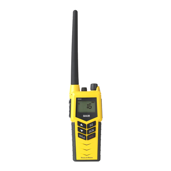
Chapter 1 Introduction Your VHF GMDSS SP3520, your new SAILOR portable VHF transceiver, is approved to fulfil the GMDSS requirements for portable VHF radios for Safety at Sea and is waterproof to the IP67 standard. As part of the required safety equipment, the SAILOR SP3520 is to be used in an emergency situation. -
Page 10: Performance
Introduction The display has red adjustable backlight which makes the display visible even at night. The radio is equipped with a lanyard and a belt clip. A huge accessory program comes with the SAILOR SP3500 series. Please find the nearest SAILOR distributor on www.thrane.com. Performance For best performance of the transceiver keep the following in mind: •... -
Page 11: Controls
Chapter 2 Operation Controls Keys and buttons 1. On/off/volume 2. Light/Lock 3. Push To Talk (PTT) 4. Up key 5. Down key 6. Hi/Lo output power 7. Squelch 8. Scan 9. Priority channel (16)/ Call channel 0641 Busse-Yachtshop.de info@busse-yachtshop.de... - Page 12 Operation Key presses Pressing and holding certain keys gives access to additional functions, shown in the table below. Extra long Short press Long press press (1 beep) (2 beeps) (3 beeps) Show next available Run through available Run through item in the list (up or items, or available down).
-
Page 13: The Display
Operation The display The display holds various fields of information, explained below. 1. Current working channel. 2. Current channel mode. 3. “Lo”: Reduced transmitter power. Full transmitter power is not shown in display. 4. Dual watch activated. 5. Current working channel is marked for scanning. 6. -
Page 14: Using The Vhf Gmdss
Operation Using the VHF GMDSS Basic functions Before using the radio, mount the antenna at the top of the Note radio. The antenna is delivered with the radio. Switching the radio on and off • To switch the radio on, turn the knob at the top of the radio clockwise. - Page 15 Operation Activating a call To activate a call to the selected channel, press and hold the PTT button on the side of the radio. The radio transmits as long as the PTT button is pressed. A small Tx sign next to the channel num- ber indicates when the radio is in transmit mode.
- Page 16 Operation Using Dual watch To activate Dual watch, press the SCN key. The display shows “Dual” at the top and “16” at the bottom right. The radio toggles between the selected channel and channel 16. • To terminate Dual watch, press SCN again. Scanning channels •...
-
Page 17: Other Functions
Operation Other functions Programming the Call channel To program the Call channel, do as follows: 1. Press and hold 16/C until the current Call channel number is flashing. 2. Select the channel with 3. Press 16/C to confirm. Programming the channel memory To add a channel to the channel memory, select the channel and then press and hold the SCN key until the display shows MEM at the top. -
Page 18: Configuring The Vhf Gmdss
Operation Configuring the VHF GMDSS Entering and using configuration mode The radio is not operational in configuration mode. Note • To enter configuration mode, press and hold the Light/Lock button while turning on the radio. The bottom line of the display shows the current menu item/setting. •... -
Page 19: Configuration Settings
Operation Configuration settings Configuration mode is used to program preferred channels and volume of key beep and battery alarm. The following settings are available in configuration mode. BEEP Status click/beep sound on key press, long press (settings/programming saved) and battery alarm. Maximum level. Status click/beep sound on key press, long press (settings/programming saved) and battery alarm. - Page 20 Operation 0643 Busse-Yachtshop.de info@busse-yachtshop.de...
-
Page 21: Batteries
Chapter 3 Batteries Battery types • The yellow primary battery pack contains a non-rechargeable Lithium battery. This battery pack is only to be used in case of emergency. • The black secondary battery pack contains a rechargeable battery. This battery pack is for daily use. The primary battery The yellow primary battery pack is only for emergency use, Important... -
Page 22: The Secondary Battery
Batteries The secondary battery Battery level indication The black secondary battery pack is for daily use of the radio. When the battery level is low, you should recharge the battery. The radio display shows the battery status. When the battery symbol is empty and flashing, the battery should be recharged as soon as possible. -
Page 23: The Battery Charger
Batteries The battery charger The charger has two compartments. • A rear compartment for storing a spare battery. It does not have a charger function. • A front compartment for recharging the battery alone or while attached to the radio. Installing the charger Mounting the charger There are several options for... -
Page 24: Recharging The Secondary Battery
Batteries Connecting to power The charger can be supplied with DC or AC. DC: Connect the 12-24VDC Connection Cable between the DC supply and the connector on the underside of the charger. AC: Connect the AC/DC adapter to the connector on the underside of the charger. -
Page 25: External Equipment
Chapter 4 Equipment and accessories External equipment List of equipment The following equipment can be connected to the radio: • SAVOX 400E Push-To Talk unit • SAVOX C500 Fist Mike • SAVOX NC/400 Noise-com • SAVOX HC-E Helmet-com • SAVOX K53004 Helmet unit •... -
Page 26: Impact On Radio Operation
Equipment and accessories When external equipment is connected to the radio, the right side of the display will show a headset. Impact on radio operation The external equipment can have a built-in PTT, speaker and microphone. Thus connecting it to the radio will have the following impact on the radio operation: •... -
Page 27: Accessories
Equipment and accessories Accessories List of accessories The following accessories are delivered with your radio: Accessory Part number Primary battery (yellow, non-rechargeable), B3501 403501A Secondary battery (black, rechargeable), B3502 403502A Charger, CH3507 403507A AC/DC converter, (100-240V~ /12VDC out), length 150cm 88-124371 12-24VDC Connection cable, length 150cm 37-124381... -
Page 28: Attaching And Removing The Belt Clip
Equipment and accessories Attaching and removing the belt clip To attach the belt clip, slide the belt clip upwards into the rails at the back of the radio until it locks. To remove the belt clip, press the projection at the top of the belt clip to release the lock and slide the belt clip downwards out of the rails. -
Page 29: Displaying Errors
Chapter 5 Troubleshooting Displaying errors Some errors result in an error message in the display. These error messages are listed below. Display text Problem Type Actions The battery voltage is Severe. Change/recharge below a critical level, Radio is non- the battery. EMPTY BAT where further operation functional. - Page 30 Troubleshooting 0703 Busse-Yachtshop.de info@busse-yachtshop.de...
-
Page 31: Technical Specifications
Appendix A Technical specifications Technical data General Item Specification RX frequency range 155.000 - 163.425 MHz TX frequency range 155.000 - 161.450 MHz Modulation 16K0G3E Power 7.2 VDC special Li battery Current drain at 2 W TX 1.4 A Current drain at 1 W TX 0.8 A Current drain RX max audio 0.25 A... -
Page 32: Transmitter
Technical specifications Transmitter Item Specification RF output power 2 W /1 W Max deviation ±5 kHz Spurious emission < 0.25 uW Adjacent channel power > 70 dB Receiver Item Specification Sensitivity (20 dB SINAD) -117 dBM typical Intermodulation 70 dB typical Spurious response >... -
Page 33: Battery Life Guidelines
Technical specifications Battery life guidelines Primary battery (non-rechargeable) The primary non-rechargeable battery pack is capable of providing sufficient power for the specified 8 hours according to regulations. The battery is marked with an expiry date. Replace the battery at or before this date. -
Page 34: Dimensional Drawing, Transceiver
Technical specifications Dimensional drawing, transceiver 0643 Busse-Yachtshop.de info@busse-yachtshop.de... -
Page 35: Dimensional Drawing, Charger
Technical specifications Dimensional drawing, charger Mounting Possibillities Desktop mounting, top view Wall mounting, rear view 0703 Busse-Yachtshop.de info@busse-yachtshop.de... - Page 36 Technical specifications 0643 Busse-Yachtshop.de info@busse-yachtshop.de...
- Page 37 Busse-Yachtshop.de info@busse-yachtshop.de...
- Page 38 TT-98-124294-A Issue: A/0703 Thrane & Thrane A/S • info@thrane.com • www.thrane.com Busse-Yachtshop.de info@busse-yachtshop.de...
Need help?
Do you have a question about the SAILOR SP3520 VHF GMDSS and is the answer not in the manual?
Questions and answers