Table of Contents
Advertisement
Advertisement
Table of Contents

Related Manuals for Sailor 6222


Summary of Contents for Sailor 6222
- Page 1 USER MANUAL SAILOR 6222 VHF DSC...
- Page 3 SAILOR 6222 VHF DSC User manual Document number: 98-131184-A Release date: January 24, 2011...
- Page 4 2015, by sending a money order or check for DKK 50 to: SW Technology/GPL Compliance, Thrane & Thrane A/S, Lundtoftegaardsvej 93D 2800 Lyngby DENMARK Please write "source for product SAILOR 6222 VHF DSC" in the memo line of your payment.
- Page 5 You may also find a copy of the source at http://www.thrane.com/foss. This offer is valid to anyone in receipt of this information. Warranties Any attempt to install or execute software not supplied by Thrane & Thrane on this device will result in the warranty being void. Any attempt to modify the software on this device in a way not specified by Thrane &...
-
Page 6: Safety Warning
Thrane & Thrane assumes no liability for the customer's failure to comply with these requirements. Ground the equipment To minimise shock hazard, the SAILOR 6222 VHF DSC unit must be connected to an electrical ground and the cable instructions must be followed. RF exposure hazards and instructions Your Thrane &... -
Page 7: Emergency Calls
Emergency calls L L L L L if if if if ift C t C t C t Cov ov ov ov over er er er er P P P P P r r r r r e e e e e s s s s s s RED Button s RED Button s RED Button s RED Button... - Page 8 SAILOR 6222 VHF DSC is designed for occupational use only and must be operated by licensed personnel only. SAILOR 6222 VHF DSC is not intended for use in an uncontrolled environment by general public. SAILOR 6222 VHF DSC is designed for installation by a skilled...
- Page 9 Training information The SAILOR 6222 VHF DSC is designed for occupational use only and is also classified as such. It must be operated by licensed personnel only. It must only be used in the course of employment by individuals aware of both the hazards as well as the way to...
- Page 10 antenna having a maximum gain of 3 dB (5.2dBi). This means all persons must be at least 3 ft. (0.9m) away from the antenna when the radio is transmitting. Installation 1. An omni-directional antenna with a maximum power gain of 5.2 dBi must be mounted at least 9.6 ft.
-
Page 11: Manual Overview
Appendix with Technical specifications and Maritime channels. Important All installation information and instructions are not covered in this manual. Please download the SAILOR 6222 VHF DSC Installation manual (98-132904) at http://extranet.thrane.com/. In the installation manual you can read how to mount the VHF radio and how to connect accessories and external equipment, including detailed system configuration examples with cable specifications. -
Page 13: Table Of Contents
Setup ................38 Chapter 3 Service & maintenance Contact for support ............47 Maintenance ..............47 Troubleshooting guide .............49 Warranty and returning units for repair ......53 App. A Technical specifications Transceiver unit SAILOR 6222 VHF DSC ......55 General DSC specifications ..........58... - Page 14 Table of Contents NMEA data rates and formats ...........59 SAILOR 6090 Power Converter 24—12 V ......60 App. B Maritime channels International channels (INT) ..........61 US channels ..............62 CA channels ..............63 BI channels ..............64 Glossary ..................65 Index ..................67...
-
Page 15: Chapter 1 Introduction
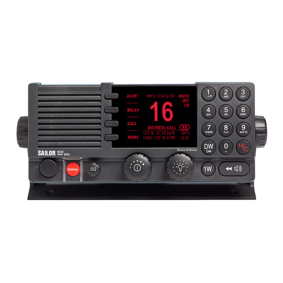
With SAILOR connection boxes the VHF radio connects easily to external equipment like additional handsets, water proof hand microphones, control speaker microphone, alarm panel or external speaker. The Ethernet interface enables the VHF radio to be connected to ThraneLINK for remote control and service updates. - Page 16 Chapter 1: Introduction Controls on the front plate 1. Loudspeaker. 2. Four soft keys with function title in the display. 3. Large display. 4. Keys 0 to 9 to enter numbers or text. 5. DW button to toggle the watch function (dual or triple). 6.
- Page 17 Chapter 1: Introduction SAILOR 6222 VHF DSC display The picture shows the display after start-up. The display holds various fields of information, ALERT depending on the currently selected function. RELAY 1. Functions you can select with DISTRESS/CALL CALL the soft keys. If there are more...
-
Page 18: Accessories Available
SAILOR 6201 One SAILOR 6201 Handset with Handset with cradle cradle is included in the delivery (additional) of the SAILOR 6222 VHF DSC. You can connect another 2 SAILOR 6201 Handsets. SAILOR 6203 SAILOR 6203 Handset with Handset with cradle cradle, waterproof to IPx6. - Page 19 5m connection cable for bulkhead mount: Use this cable in installations where the SAILOR 6201 or 6203 Handset is not connected directly to the SAILOR 6222 VHF, but located in a different position. 5m Connection cable, 1x10 pole: Use this cable in installations when connecting external equipment to the SAILOR 6222 VHF.
- Page 20 5 ports. SAILOR 6090 Power The SAILOR 6090 Power Converter Converter 24 V to is used to provide 12 V DC for the 12 V DC SAILOR 6222 VHF DSC from a 24 V DC power source. Accessories available...
- Page 21 Chapter 1: Introduction System configuration — example The SAILOR 6222 VHF DSC can be customized to suit your installation. The following illustration is one example of a system. For further configuration examples see the installation manual, Appendix B, System configurations.
- Page 22 Chapter 1: Introduction Accessories available...
-
Page 23: Chapter 2 Operation
Note Before using the VHF radio make sure that the VHF and DSC antennas, power cable and other external equipment are connected properly. For installation instructions see the SAILOR 6222 VHF DSC Installation manual (download only). Overview In this chapter you find detailed instructions and guidelines for: •... -
Page 24: General Use And Navigation
Chapter 2: Operation General use and navigation Power on and volume in handset and speaker The VHF radio has a dual-function on/off wheel knob for power on/off and volume control. To power on the VHF radio press the on/off wheel knob. To power off the VHF radio, press and hold the on/off wheel knob and follow the instructions in the display. - Page 25 Chapter 2: Operation Speaker devices The VHF radio can be equipped with the following speaker devices: • SAILOR 6201/6203 Handset with cradle and PTT (Push To Talk) button. • SAILOR 6202 Handmicrophone with PTT button. • SAILOR 6204 Control Speaker Microphone with PTT button.
- Page 26 Position and MMSI number The position and MMSI number for the SAILOR CALL 6222 VHF DSC radio is always shown in the DSC window (the lower half of the radio’s display) ALERT in stand-by mode. The display shows also the...
- Page 27 Chapter 2: Operation Soft-key functions A number of functions of the SAILOR CALL 6222 VHF DSC are accessed and set using the four soft keys to the left of the ALERT display. The current function of a soft DISTRESS/CALL key is shown in the display next to the DROBOS soft key.
-
Page 28: Adjusting The Squelch Level
Chapter 2: Operation Changing the display light, night view Red text on black background is available for optimal night vision. To dim the display backlight, e.g. to give comfortable night vision, press, hold and turn the selector wheel knob anti-clockwise. The display shows a brightness bar. -
Page 29: Vhf Radio Communication
Chapter 2: Operation VHF radio communication Basic VHF operation You can make VHF calls using the Handset or another speaker device. Note A single, short press on the 16/C key always brings you to channel 16, the international calling and distress channel, no matter what state the radio is in. - Page 30 Chapter 2: Operation 5. Suggest a working channel other than 16 by saying: “Channel [suggested channel number]”. 6. Say: “Over.” and release the PTT button to allow the caller to confirm the suggested new channel. 7. Switch to the new channel using the keypad or by turning the selector wheel knob to the agreed channel and begin your conversation.
- Page 31 Chapter 2: Operation • Primary channels • Weather channels (if any) • Private channels (if any) With a long press on the selector wheel knob the radio changes to channel 16 for the channel tables INT and BI, and to channel 9 for the channel tables US and CA.
- Page 32 Chapter 2: Operation Engagement status The radio is engaged when an active DSC-initiated communication is ongoing, or communication is active on non-DSC initiated VHF operation: • A new channel selected • PTT pressed or, • Voice signal received The engagement state is used to prohibit incoming DSC calls from taking over control of the transmitter channel, disrupting ongoing communication.
-
Page 33: Watch
2. Press the soft key OVRIDE to transmit with full power. When you release the PTT button, the transmission power goes back to low. Watch The SAILOR 6222 VHF DSC radio Dual watch Triple watch has a watch function with dual or triple watch. -
Page 34: Scan
Chapter 2: Operation Scan The radio has a scanning function for tagged voice channels. Any available voice channel, including weather and private channels, can be tagged and added to the scanning sequence. As default the radio scans with priority scanning of channel 16. If a signal is received while in any scanning mode, only channel 16 continues to be watched. -
Page 35: Dsc Calls
Chapter 2: Operation DSC calls In this section of the manual you find information on: • Sending, acknowledging and cancelling own distress • DROBOS — Distress Relay on behalf of someone else • Receiving distress calls • DSC calls for communication Sending, acknowledging and cancelling own distress To send a distress message 1. - Page 36 Chapter 2: Operation Having pressed the red distress button and sent the distress message, the following information is displayed: • STATION: shows the radio’s MMSI number. • NAT: shows the nature of distress, see also ALERT: To send a distress message with specified nature.
- Page 37 Distress button for 3 seconds. To receive acknowledgement of own distress When the SAILOR 6222 VHF DSC receives an acknowledgement of distress from another vessel or station, a 2-tone alarm sounds. The display shows a pop-up window with the MMSI number of the station who sent the distress acknowledgement call.
- Page 38 Chapter 2: Operation 3. The SAILOR 6222 VHF DSC will send the self-cancellation call on channel 70 and the display automatically shows the message that you should say when cancelling the distress with a radio message. Use the selector wheel knob to scroll through all displays with information for the voice cancel.
- Page 39 Chapter 2: Operation The VHF radio is now in distress mode. Continue the distress traffic and procedures from the VHF radio front panel, if possible, in the same way as described for handling distress mode from the main VHF radio. Press the MUTE button on the Alarm panel to mute the audible alarm on incoming distress or urgency messages.
-
Page 40: Receiving Distress Calls
Chapter 2: Operation Relay items Description NATURE: Select the nature of distress: FIRE, EXPLOSION FLOODING COLLISION GROUNDING LISTING (in danger of capsizing) SINKING DISABLED (and adrift) UNDESIGNATED ABANDONING (ship) PIRACY (armed robbery attack) MAN OVERBOARD EPIRB LAT: Enter the position and UTC information or unknown of LON: the vessel in distress. - Page 41 Chapter 2: Operation 3. Monitor channel 16 as a coast station may require your assistance. If the radio is not on channel 16, turn the selector wheel knob or use the key 16/C to go to channel 16. 4. Then the radio receives the first distress QUIT acknowledgement call and the 2-tone alarm sounds again.
- Page 42 Chapter 2: Operation DSC calls for communication With a DSC call you can establish a radio communication with one or several specific radios on a suggested VHF channel. 1. DSC call message from Radio A to Radio B 2. DSC acknowledge from Radio B to Radio A 3.
- Page 43 Chapter 2: Operation 5. In the field CH: enter the suggested VHF channel for following communication. 6. Press the soft key SEND to make the call. What is a Session? A DSC session is defined as a collection of DSC calls (transmitted and/or received) that are related to the same event (e.g.
- Page 44 Chapter 2: Operation The session line can be one of the following: Session line Explanation OWN DISTRESS The ship is in own distress. See also To send a distress message on page 21. DISTRESS RX You watch or participate in a distress communication for another station in distress RELAY calls (numerous) You watch or participate in a distress communication for another station in distress...
- Page 45 Chapter 2: Operation Soft keys to control DSC sessions Call or session types vary in control options, and options may also change if a session changes its state. The following table gives an overview of the DSC soft key commands available: Soft key —...
- Page 46 Chapter 2: Operation Soft key — DSC session Radio function ANNUL (Cancel Own Cancels an inadvertently transmitted distress Distress) CONFIRM (Cancel Own Confirms action and proceed sequence, used in Distress) cancel distress procedure INFO (in Cancel Own Turns page of text message. Distress) HIST (Received A filtered version of the log displaying received calls...
- Page 47 Chapter 2: Operation For other session types the soft key function INFO typically shows the details from a single call. Detail fields for other calls than distress are: INFO —other calls Explanation CALL Type (on received call) – The call type may be shown on call reception Category of the call: Urgency, Safety or Routine FROM...
-
Page 48: Handling Multiple Calls - Dsc And Voice
Chapter 2: Operation Handling multiple calls — DSC and voice The SAILOR 6222 VHF DSC can control multiple DSC sessions simultaneously with a VHF communication session. All sessions can keep track of their session state and the communication channel used. They are handled in their respective sessions, in the order as they are started up. -
Page 49: Phone Book
Chapter 2: Operation • V — Voice (VHF voice call, non-DSC) State of session icon Meaning for the current call (DSC or voice) (inverted) Active call/session Call on hold Flashing Call has updates that need handling or viewing Phone book Use the phone book when making a DSC call. - Page 50 Chapter 2: Operation Adding a contact to the phone book To add a contact to the phone book do as follows: 1. Press the soft key PHBOOK. If it is not in the display, press the soft key MORE until PHBOOK appears in the display. 2.
-
Page 51: Replay Function
Chapter 2: Operation Editing a contact 1. Press the soft key PHBOOK. If it is not in the display, press the soft key MORE until PHBOOK appears. 2. Press the soft key EDIT. 3. Press and turn the selector wheel knob to browse through the details of the contact and continue as described in Adding a contact to the phone book from step 2 onwards. -
Page 52: Setup
Chapter 2: Operation The recorded channel is displayed. The message length is shown in seconds. The display shows how old the message is. If the 240 s storage limit is reached, the oldest data is overwritten. Note The replay function can be started even in a distress situation. If a DSC call is received the replay function continues the playback. -
Page 53: Radio Setup
Chapter 2: Operation • System setup • Controller setup Accessing a setup page To change a setting in one of the SETUP pages, do as follows 1. Press the soft key SETUP. If it is not in the display, press the soft key MORE until SETUP appears. - Page 54 Chapter 2: Operation Para- Description meter Watch DUAL: Dual watch monitoring the working channel and the Mode priority channel (channel 16, default for international channels). TRIPLE: Triple watch. The working channel is watched with the priority channel (channel 16) and the programmed call channel (if any, otherwise dual watch).
- Page 55 Chapter 2: Operation Channel setup Para- Description meter To select the channel table for the primary channel. Channel Channel tables available: INT, BI, US, CA. See also VHF channel table on Mode page 17. Band- Selection of the bandwidth for the fixed pre-programmed width channels.
-
Page 56: Power Supply
Para- Description meter Monitor Set this to ENABLED if the radio is connected to a SAILOR 6081 Power Supply Unit and Charger. Set this to DISABLED for any other power supply. Status Visible if ENABLED. Current status of the connected power supply. - Page 57 Chapter 2: Operation DSC setting Description Auto-Ack Individual Auto acknowledgement of individually addressed, non distress DSC messages ON (default) Non-Distr. Inactivity Inactivity time-out to exit non-distress functions (e.g. in setup) without automatic time-out (OFF): Range: OFF, 1 to 30 minutes, in 1 min. steps Default: 15min.
-
Page 58: System Setup
Chapter 2: Operation DSC setting Description DSC Self Test You can set the radio to run a DSC self test. OFF: Disabled (default) RUN: Run test. For further details about this test see DSC routine testing on page 50. DSC call logs Use the soft keys to leaf through all logs. -
Page 59: Controller Setup
Chapter 2: Operation SYSTEM SETUP Description Factory Defaults Resets the radio to factory defaults. Press the selector wheel knob and confirm the reset to factory default. Radio Info: SW Version: Software version of the radio S/N: Serial number of the radio TU IP: IP address of the radio Password If you need to change the identity of the radio... - Page 60 Chapter 2: Operation Top-level standby soft-key functions and setup pages TOP-LEVEL STAND-BY SETUP PAGES CALL EXIT RADIO SETUP Scan Hang Time PHBOOK Scan Resume Watch mode Priority Scan ALERT EXIT ATIS code DROBOS EXIT CHANNEL SETUP Channel Mode PHBOOK Bandwidth Int.
-
Page 61: Chapter 3 Service & Maintenance
Maintenance Preventive maintenance Maintenance of the SAILOR 6222 VHF DSC can be reduced to a maintenance check at each visit of the service staff. Inspect the radio for mechanical damages, salt deposits, corrosion and any foreign material. Due to its robust construction and ruggedness the radio has a long lifetime. - Page 62 Chapter 3: Service & maintenance DSC self test To run a control routine DSC self test, do as follows: 1. Press the soft key SETUP. If it is not in the display, press the soft key MORE until SETUP appears. 2.
-
Page 63: Troubleshooting Guide
Chapter 3: Service & maintenance Troubleshooting guide Action Symptom Remedy The radio The display Check if power is present. will not turn is empty. Check fuse which is placed in the power connector. Check performance of power supply if connected to one. - Page 64 Chapter 3: Service & maintenance Action Symptom Remedy DSC routine Check the DSC function regularly. Verify the testing complete DSC installation, with antennas, by transmitting a Safety Test call to another station (coast or ship). The test call is generated using the DSC call flow via menu CALL.
- Page 65 Chapter 3: Service & maintenance Action Symptom Remedy Radio time DSC logs are A wrong radio time indication should occur only if sorted with GPS position source is not connected or providing wrong time correct time data. A valid GPS time signal will stamp or update the UTC time used for time stamping the DSC radio time is...
- Page 66 In Setup, Power Supply, set Monitor to disabled. POWER supply You can only monitor the power supply if the radio is SUPPLY status powered by a SAILOR 6081 Power Supply Unit and LOST cannot be Charger. CONTACT monitored. Replacing the fuse in the power connector One fuse is installed in the power connector.
-
Page 67: Warranty And Returning Units For Repair
Chapter 3: Service & maintenance Replacing the fuse in the SAILOR 6090 Power Converter One fuse is installed in the SAILOR 6090 Power Converter. If the fuse is blown, do as follows: 1. Track down why the fuse was blown and solve the problem. - Page 68 Should you need to send the product for repair, please read the below information before packing the product. The shipping carton has been carefully designed to protect the SAILOR 6222 VHF DSC and its accessories during shipment. This carton and its associated packing material should be used when repacking for shipment.
-
Page 69: Transceiver Unit Sailor 6222 Vhf Dsc
Appendix A Technical specifications Transceiver unit SAILOR 6222 VHF DSC Item Specification Weight SAILOR 6222 VHF DSC < 1.50 kg (3.3 lbs) approximately Box weight 3.8 kg (8.4 lbs) approximately, including SAILOR SAILOR 6222 VHF DSC 6201 Handset and wall mount cradle, SAILOR 6090 Power Converter and Installation and user manual in box. - Page 70 50 Ohm antenna, 50 Ohm female SO239 for PL259 plug 2-antenna operation for VHF and DSC communication Water ingress IPx8 and IPx6 all over. For flush-mount installations a sealing gasket is included in the delivery. Transceiver unit SAILOR 6222 VHF DSC...
- Page 71 Receiver Sensitivity < -119 dBm typically @ 20 dB SINAD CCITT weighted LF power Built-in loudspeaker: 6 W (at 5 kHz dev./1 kHz tone) External loudspeaker: 6 W / 8 Ohm Distortion Below 5% Transceiver unit SAILOR 6222 VHF DSC...
-
Page 72: General Dsc Specifications
Appendix A: Technical specifications Item Specification S/N ratio Better than 43 dB Spurious emissions Below 2 nW Spurious response rejection More than 74 dB Intermodulation response More than 73 dB Co-channel rejection Better than —10 dB Adjacent channel selectivity More than 74 dB Blocking level More than 94 dBV General DSC specifications... -
Page 73: Nmea Data Rates And Formats
Appendix A: Technical specifications Item Description Residual modulation Below —26 dB NMEA data rates and formats Item Value 61162-1 4800,8,n,1 61162-2 38400,8,n,1 NMEA data rates and formats... -
Page 74: Sailor 6090 Power Converter 24-12 V
Appendix A: Technical specifications SAILOR 6090 Power Converter 24—12 V Item Description Weight 300 g Dimensions Height: 33 mm Width: 190 mm Depth: 85 mm Operating temperature -25°C to 55°C (5°F to 131°F) Storage temperature -30°C to 80°C (-22°F to 176°F) Input voltage 21—32 VDC... -
Page 75: Maritime Channels
Appendix B Maritime channels International channels (INT) Channels SIMPLEX DUPLEX Channels SIMPLEX DUPLEX Intership Port Port Public Intership Port Port Public 156,050 160,650 156,025 160,625 156,100 160,700 156,075 160,675 156,150 160,750 156,125 160,725 156,200 160,800 156,175 160,775 156 250 160 850 156,250 160,850 156 225 160 825 156,225 160,825... -
Page 76: Us Channels
Appendix B: Maritime channels US channels Channels SIMPLEX DUPLEX Channels SIMPLEX DUPLEX Channels 156,050 156,050 162,550 162,400 162,475 156,175 156,175 162,425 156,250 156,250 162,450 156,300 156,300 156,275 156,275 162,500 156,350 156,350 156,325 156,325 162,525 156,400 156,400 156,375 156,375 156,450 156,450 156,425 156,425 156,500 156,500 156,475 156,475... -
Page 77: Ca Channels
Appendix B: Maritime channels CA channels Channels SIMPLEX DUPLEX Channels SIMPLEX DUPLEX Channels 156,050 160,650 156,025 160,625 162,550 156,100 160,700 156,075 156,075 162,400 156,150 160,750 156,125 156,125 162,475 156,200 156,200 156,175 156,175 162,425 156,250 156,250 156,225 160,825 162,450 156,300 156,300 156,225 156,225 162,500 156,350 156,350... -
Page 78: Bi Channels
Appendix B: Maritime channels BI channels Channels SIMPLEX DUPLEX Channels SIMPLEX DUPLEX Intership Port Port Public Intership Port Port Public 156,050 160,650 156,025 160,625 156,100 160,700 156,075 160,675 156,150 160,750 156,125 160,725 156,200 160,800 156,175 160,775 156,250 160,850 156,225 160,825 156,300 156,300 156,275 160,875 156,350 160,950... -
Page 79: Glossary
Glossary Glossary Automatic Identification System, a short range coastal tracking system used on ships and by Vessel Traffic Services for identifying and locating vessels by electronically exchanging data with other nearby ships. ATIS Automatic Transmission Identification System DROBOS Distress Relay On Behalf Of Someone else Digital Selective Calling EPIRB Emergency Position-Indicating Radio Beacon. - Page 80 Glossary Transceiver Unit Coordinated Universal Time. The International Atomic Time (TAI) with leap seconds added at irregular intervals to compensate for the Earth’s slowing rotation. Leap seconds are used to allow UTC to closely track UT1, which is mean solar time at the Royal Observatory, Greenwich.
-
Page 81: Index
Index Index Numerics 16/C, 10, 15 background sessions 90 s replay, 37 DSC, 34 backlight, 1 dim, 10 Bi, 64 Bi channels, 64 acknowledgement, distress, 23 browse channels, 10 action line, display, 3 activate scan resume, 39 scanning, 20 watch, 19 CA channel table, 41 ADD, 36 CA channels, 63... - Page 82 Index channels distress Bi, 64 acknowledgement, 23 CA, 63 cancelling, 23 international, 61 display, 22 primary, 17 message relay, 25 private, 17 nature, 22 US, 62 power failure, 24 weather, 17 received calls, 26 Colour theme, 44 send from alarm panel, 24 Comm Inactivity, 43 time since activation, 22 configuration...
- Page 83 Index editing a contact, 37 icons Emergency call sheet, ix session state, 29 emergency calls, v input end call, 18 NMEA, 44 engagement installation terminate, 18 cradle for 6201, 4 time out, 18 handset cradle, 4 engagement status, 18 installation guide, A3, ix enter position manually, 12 installation manual, ix EPIRB...
- Page 84 Index menu, overview, 46 position data message enter manually, 42 replay, 37 position Info, 42 MMSI power change, 45 fuse, 52 wrong number in the radio, 50 off, 10 monitor power supply, 42 on, 10 MORE, 13 Power Converter multiple calls, DSC, 34 fuse, 53 mute power failure...
- Page 85 Index soft key, 13 ADD, 36 DSC self test, 44 ALERT, 22 CALL, 35 DELETE, 37 DISACK, 27 safety summary, iv DROBOS, 13, 25 salt deposits, 47 DSC, 31 scan FILTER, 20 add channel, 20 LOCAL, 18 hang time, 39 MORE, 13 priority, 40 OVRIDE, 19...
- Page 86 Index Volume wheel knob, 2 TAG, 20 remove, 20 tagged channels warnings, 47 view, 20 warranty, 53 technical data, 55 limitation, iv temperature WATCH, 19, 20 operational, 55, 60 watch storage, 55, 60 dual and triple, 19 terminate dual or triple, 40 engagement, 18 setup, 39 theme...
- Page 88 98-131184-A Thrane & Thrane A/S info@thrane.com www.thrane.com • •...
Need help?
Do you have a question about the 6222 and is the answer not in the manual?
Questions and answers