Table of Contents
Advertisement
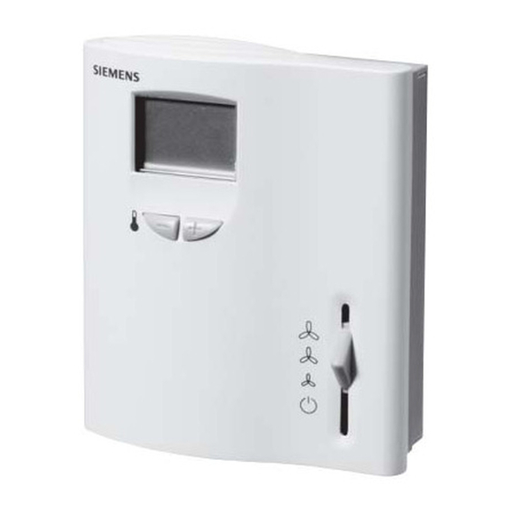
RDF Series Room Temperature
Controllers
Product Description
Room Temperature Controllers with LCD for two-
pipe (with and without an electrical heater) and four-
pipe fan coil units.
Product Numbers
Part Number
RDF10U
Two-pipe fan coil units
RDF20U
Two-pipe fan coil units with
electrical heater
RDF30U
Four-pipe fan coil units
RDF50.1U
Two-pipe fan coil units with 0 to 10
Vdc output
Required Tools
•
Small, flat-blade screwdriver
•
Wire strippers
•
Electric drill
Expected Installation Time
30 minutes
Accessories
•
141-570 Lockable Thermostat Guard
•
ARG70 Wall Plate Adapter
•
QAH11.1 Remote/Changeover Sensor
Item Number 129-497, Rev. BA
Application
Installation Instructions
Installation
Step 1. Loosen retaining screws.
Step 2. Remove controller housing.
Step 3. Mount base plate to wall.
Step 4. Remove screw and open terminal cover.
Document No. 129-497
May 18, 2011
Page 1 of 7
Advertisement
Table of Contents

Related Manuals for Siemens RDF10U


Summary of Contents for Siemens RDF10U
-
Page 1: Product Description
Room Temperature Controllers with LCD for two- pipe (with and without an electrical heater) and four- pipe fan coil units. Product Numbers Part Number Application RDF10U Two-pipe fan coil units RDF20U Two-pipe fan coil units with Step 1. Loosen retaining screws. electrical heater... -
Page 2: Wiring Diagrams
Changeover sensor Electric heat Three-speed fan motor Digital input for day/night changeover Control valve, heat/cool or two-pipe system Cooling control valve for four-pipe system Terminal RDF10U and RDF30U Position Terminal Function Operating voltage 24 Vac negative Operating voltage 24 Vac negative... - Page 3 QAH11.1 Operating voltage 24 Vac positive 10,11,12 Fan speed output III, II, I Figure 5. RDF50.1U. Figure 4. RDF50.1U. Signal input for potential-free operating mode changeover switch QAH11.1 Figure 7. RDF10U, and RDF20U. Siemens Industry, Inc. Page 3 of 7...
-
Page 4: Operating Instructions
41°F to 95°F (5°C to 35°C). The new temperature setpoint will automatically be stored 10 seconds after the last adjustment is made. The display will then stop flashing. Page 4 of 7 Siemens Industry, Inc. - Page 5 5 seconds. Release them and within 2 seconds, press the + button again for 3 seconds. The display will show “P01”. 3. Select the required parameter by repeatedly pressing the + or – button: 3055z01 Siemens Industry, Inc. Page 5 of 7...
-
Page 6: Dip Switch Settings
Operating action of Changeover is activated Changeover is activated switch for external when switch is closed when switch is open (NC) operating mode (NO) changeover Output sequence Heating and cooling (four- Two-stage cooling pipe) Page 6 of 7 Siemens Industry, Inc. - Page 7 Information in this publication is based on current specifications. The company reserves the right to make changes in specifications and models as design improvements are introduced. Teflon is a registered trademark of DuPont. Product or company names mentioned herein may be the trademarks of their respective owners. © 2011 Siemens Industry, Inc.
Need help?
Do you have a question about the RDF10U and is the answer not in the manual?
Questions and answers