Table of Contents
Advertisement
Quick Links
User'
User' s s s s s
User'
User'
User'
Manual
Manual
Manual
Manual
Manual
nVIDIA nForce3 250Gb
nVIDIA
nVIDIA
nForce3 250Gb
nForce3 250Gb mainboard for AMD
nForce3 250Gb
nVIDIA
nVIDIA
nForce3 250Gb
Socket 754 based Athlon 64 processor
Socket 754 based Athlon 64 processor
Socket 754 based Athlon 64 processor
Socket 754 based Athlon 64 processor
Socket 754 based Athlon 64 processor
TRADEMARK
All products and company names are trademarks or registered
trademarks of their respective holders.
These specifications are subject to change without notice.
mainboard for AMD
mainboard for AMD
mainboard for AMD
mainboard for AMD
Manual Revision 1.1
April 26, 2004
Advertisement
Table of Contents

Related Manuals for EPOX nVIDIA nForce3 250Gb


Summary of Contents for EPOX nVIDIA nForce3 250Gb
- Page 1 User’ s s s s s User’ User’ User’ Manual Manual Manual Manual Manual nVIDIA nVIDIA nForce3 250Gb nVIDIA nForce3 250Gb nForce3 250Gb nForce3 250Gb mainboard for AMD mainboard for AMD mainboard for AMD mainboard for AMD nVIDIA nVIDIA nForce3 250Gb...
- Page 2 DISCLAIMER OF WARRANTIES: THERE ARE NO WARRANTIES WHICH EXTEND BEYOND THE DESCRIPTION ON THE FACE OF THE MANUFACTURER LIMITED WARRANTY. THE MANUFACTURER EXPRESSLY EXCLUDES ALL OTHER WARRANTIES, EXPRESS OR IMPLIED, REGARDING ITS PRODUCTS; INCLUDING ANY IMPLIED WARRANTIES OF MERCHANTABILITY, FITNESS FOR A PARTICULAR PURPOSE OR NONINFRINGEMENT.
- Page 3 80 Port Frequently Asked Questions Below is a list of some basic POST Codes, possible problems and solutions. For more detailed information about POST Codes, refer to Appendix D in this manual. P O ST C O D E P r o bl e m So l uti o n FFh o r CFh 1 .B IO S c hip inse rte d...
-
Page 4: Table Of Contents
Table of Contents Page Section 1 Introduction Package Contents ............1- 1 Mainboard Features ........... 1- 2 System Block Diagram ..........1- 5 Section 2 Specification Mainboard Specification ..........2- 1 Section 3 Installatio Mainboard Layout ............. 3- 2 Easy Installation Procedure ........3- 3 CPU Insertion ............. - Page 5 PNP/PCI Configuration ..........4- 15 PC Health Status ............4- 17 Power BIOS Features ..........4- 19 Defaults Menu ............4- 21 Supervisor/User Password Setting ......4- 22 Exit Selecting .............. 4- 23 Section 5 S-ATA RAID Configuration Introduction ............... 5- 1 NVidia SATA RAID Features ........
- Page 6 Page Left Blank...
-
Page 7: Introduction
Introduction Section 1 INTRODUCTION 1-1 Package Contents Contents Powerpack items (Optional) A. Mainboard I. Mini heatsink J. Tool Pen B. User’s manual K. Extra USB2.0 port cable C. Floppy drive cable Optional Items D. HDD drive cable L. S/PDIF Module E. -
Page 8: Mainboard Features
64 Processor deliver, check out the AMD website at http://www.amd.com Chipset The board is designed with NVIDIA nForce3 250Gb MCP (Media Communica- tions Processor) chipset, the single-chip 64-bit NVIDIA nForce3 architecture provides an inherent performance advantage over dual-chip implementations of the same functionality. - Page 9 Introduction Hardware Monitoring Hardware monitoring enables you to monitor various aspects of the system operation and status. This includes CPU temperature, voltage and fan speed in RPMs. GbE LAN This mainboard is optionally mounted with a Gigabit ethernet LAN chipset. The new Gigabit Ethernet LAN allows data transmission at 1,000 megabits per second (Mbps), which runs 10 times faster than conventional 10/100BASE-T Ethernet LANs.
- Page 10 Introduction Special Features Cool ‘n’Quiet Technology Reduce the noise and heat from your PC when AMD Cool’n’Quiet Technology is enabled. NVIDIA Firewall The NVIDIA Firewall is a high performance, “hardware-optimized” firewall offering enhanced reliability and protection at the end-point 80 Port An onboard LED-display trouble-shooting device, facilitating user to detect boot-up problems.
-
Page 11: System Block Diagram
Introduction 1-3 System Block Diagram Figure 5: System Block Diagram Page 1-5... - Page 12 Introduction Page 1-6...
-
Page 13: Specification
Mainboard Specification Processor Supports 754-pin Socket for AMD Athlon 64 processors with 1.6GTs Hyper Transport FSB up to 3700+ Chipset nVidia nForce3 250Gb Chipset Main Memory Three 184-pin DDR DIMM sockets for 64-bit, Unbuffered, Single/Double- side and DDR-266/333/400 DIMMs Supports up to 3GB memory size... -
Page 14: Legacy Io Controller
Specification Legacy IO Controller Winbond W83627THF LPC IO controller with floppy, printer, game, serial and SIR interface Supports Hardware Monitoring function Intelligent CPU fan speed control to lower system noise Audio Eight channel audio with analog and digital output using Realtek ALC850 AC’97 CODEC - AC’97 v2.3 compliant... - Page 15 Specification Onboard connector and pin-header floppy drive connector ATA-133 IDE connectors Four extra USB2.0 ports CD-IN and One AUX-IN connector Front Panel Audio connector S/PDIF in/out connector IR connector Game port connector Serial Port (COM2) connector S-ATA connectors ( 4 optional from Silicon Image SiI3114 chip) Three Fan connectors Front Panel Controller...
-
Page 16: Form Factor
Specification Supports NVIDIA Personal Firwall Function under Windows 2000/XP For more detailed information about NVIDIA Firewall, refer to user’s manual in the bundled CD. PowerBIOS for excellent Overclocking capabilities through - subtle voltage tuning for CPU, Memory, AGP - subtle frequency tuning on FSB with 1MHz increment - Supports complete Asynchronous FSB/Memory and Asynchronous FSB/ AGP, PCI scheme for overclocking CPU Overheating Protection... -
Page 17: Installation
Installation Section 3 INSTALLATION Note: Depending on the model you purchased, some components are optional and may not be available. Page 3-1... -
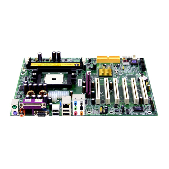
Page 18: Mainboard Layout
Installation Mainboard Layout Note: Depending on the model you purchased, some components are optional and may not be available. Page 3-2... -
Page 19: Easy Installation Procedure
Installation Easy Installation Procedure The following must be completed before powering on your new system: 3-1. CPU Installation 3-2. Jumper Settings 3-3. System Memory Configuration 3-4. Expansion Slots 3-5. Device Connectors 3-1 CPU Installation <Figure 1> <Figure 2> Step 2 Step 1 Place the retention mechanism on the Place the back plate into the two holes... - Page 20 Installation <Figure 6> <Figure 5> Step 5 Step 6 Close the socket by lowering and Align pin 1 on the CPU with pin 1 on locking the actuation lever. the CPU socket as shown in the illustration above. The CPU is keyed to prevent incorrect insertion.
- Page 21 Installation <Figure 9> Step 9 Plug the CPU fan power into the mainboard’s CPU fan connector. The installation is complete. Note: Thermal compound and qualified heatsink recommended by AMD are a must to avoid CPU overheat damage. Page 3-5...
-
Page 22: Jumper Settings
Installation 3-2 Jumper Settings JCMOS: Clear CMOS data Jumper If the CMOS data becomes corrupted or you forgot the supervisor or user password, clear the CMOS data to reconfigure the system back to the default values stored in the ROM BIOS. Settings: 1-2: Normal (Default) 2-3: Clear CMOS... -
Page 23: System Memory Configuration
Installation 3-3 System Memory Configuration Memory Layout The mainboard accommodates three PC2100/PC2700/PC3200 184-pin DIMMs (Dual In-line Memory Modules): • Supports up to 3.0GB of 266/333/400MHz DDR SDRAM. • Supports unbuffered DIMM configurations defined in JEDEC DDR DIMM specification. <Figure 10> DDR DIMM 1 DDR DIMM 2 DDR DIMM 3... - Page 24 Installation DIMM Module Installation Figure 11 displays the notch on the DDR DIMM memory module. DIMMs have 184 pins and one notch that matches with the DDR DIMM socket. DIMM modules are installed by placing the chip firmly into the socket and pressing straight down as shown in figure 12 until the white clips close and the module fits tightly into the DIMM socket (figure 13).
-
Page 25: Expansion Slots
Installation 3-4 Expansion Slots AGP Slot The mainboard is equipped with an AGP slot. Make sure you install a card that supports the 1.5V specification. PCI Slots AGP Slot The mainboard is equipped with 6 PCI slots. PCI Slots Installing an Expansion Card The steps below assume that the mainboard is already installed in the system chassis. - Page 26 Installation AGP Card Installation Caution 1. AGP card component is blocked by DIMM socket lock. 2. AGP slot clicker is not locked. 3. AGP card edge connector is not inserted properly. 1. AGP card component is not blocked by DIMM socket lock. 2.
-
Page 27: Device Connectors
Installation 3-5 Device Connectors The I/O back panel for this mainboard is shown below. When installing the mainboard into the computer case, use the bundled I/O shield to protect this back panel. RJ45 Parallel Port 7.1 Audio Channel PS/2 Mouse PS/2 Keyboard S/PDIF-out... - Page 28 Installation Floppy Controller Connector This mainboard connects floppy disk drive. IDE1/IDE2:Ultra DMA-100/133 Primary/Secondary IDE Connector This mainboard is equipped with 2 IDE connectors IDE2 IDE1 to support up to 4 ATA-100/133 IDE drives. It supports PIO and DMA mode operations for maximum data transfer rate of 133MB/sec per channel.
- Page 29 Installation CFPA: Front Panel Audio Connector When the jumpers are removed this connector can be used for front panel audio. The front panel phone jack should have “normal close” switch. Without phone plug inserted, the rear panel audio is enabled. With phone plug inserted, the rear panel audio will be disabled.
- Page 30 Installation SPDIF: Sony/Philips Digital InterFace connector This connector links digital audio between the mainboard and your audio devices, such as CD player, sampler or DAT recorder. It allows the digital transmission of audio data in S/PDIF format. SPDIF_IN SPDIF_OUT GAME1: Game/MIDI connector This port works well with any application that is compatible with the standard PC joystick.
- Page 31 Installation SATA1 / SATA2: Serial ATA Connectors SATA3 / SATA4 / SATA5 / SATA6 (Optional): Serial ATA Connectors from Silicon Image SiI3114 chip. These connectors enable you to connect Serial SATA2 SATA1 ATA devices that conform to the Serial ATA specification.
- Page 32 Installation LED: 80 Port Debug LED Provides two-digit POST code to show why the system fail to boot. Allows quick and easy optimization. 80 Port Debug 7-segment LED display (Refer to Appendix D for POST codes) Page 3-16...
- Page 33 Installation CFP: Front Panel Connector HD_LED This LED will light up whenever the hard drive is being accessed. PWR_LED This connects to the power button of the system chassis This switch allows you to reboot without having to power off the system thus prolonging the life of the power supply or system.
-
Page 34: Power-On/Off (Remote)
Installation 3-6 Power-On/Off (Remote) This board has a 20-pin ATX and a 4-pin ATX12V power supply connector to support power supplies with Remote On/Off feature. The chassis power button should be connected to the mainboard front panel PW_ON header (Figure 15). You can turn off the system in two ways: by pressing the front panel power On/Off button or using the "Soft Off"... - Page 35 Installation 3-8 ACPI S3 (Suspend To RAM) Function This mainboard supports the STR (Suspend To RAM) power management scheme by maintaining the appropriate power states in the DDR SDRAM interface signals. The power source to the DDR SDRAM is kept active during STR (ACPI S3).
-
Page 36: Cpu Overheating Protection
Installation 3-9 CPU Overheating Protection This mainboard is equipped with CPU Overheating Protection. It will automati- cally remove power to shutdown the system when CPU temperature reaches approximately 110°C. This is to prevent long term damage to the CPU from overheating. -
Page 37: Bios Setup
BIOS Section 4 BIOS SETUP Main Menu The ROM BIOS contains a built-in Setup program which allows user to modify the basic system configuration and hardware parameters. The modified data is stored in a battery-backed CMOS, so that data will be retained even when the power is turned off. -
Page 38: Standard Cmos Setup
BIOS The main menu displays all the major selection items. Select the item you need to reconfigure. The selection is made by moving the cursor (press any direction (arrow key ) to the item and pressing the ‘Enter’ key. An on-line help message is displayed at the bottom of the screen as the cursor is moved to various items which provides a better understanding of each function. -
Page 39: Advanced Bios Features
BIOS 4-2 Advanced BIOS Features Selecting the “ADVANCED BIOS FEATURES” option in the CMOS SETUP UTILITY menu allows users to change system related parameters in the displayed menu. This menu shows all of the manufacturer’s default values for the board. Pressing the [F1] key displays a help message for the selected item. - Page 40 BIOS First /Second/Third Boot Device The BIOS attempts to load the operating system from the devices in the sequence selected in these items. Options: Floppy, LS120, Hard Disk, CDROM, ZIP100, USB-FDD, USB-ZIP, LAN, Disabled. Boot Other Device When enabled, the system searches all other possible locations for an operating system if it fails to find one in the devices specified under the first, second, and third boot devices.
-
Page 41: Advanced Chipset Features
BIOS 4-3 Advanced Chipset Features Choose the “ADVANCED CHIPSET FEATURES” option in the CMOS SETUP UTILITY menu to display following menu. Figure 4: Chipset Features Setup DRAM Configuration Scroll to DRAM Configuration and press <Enter>. The following screen appears: Max Memclock (Mhz) This item sets the memory clock. - Page 42 BIOS CAS# Latency (Tcl) Enables you to select the CAS latency time. The value is set at the factory depending on the DRAM installed. Do not change the values in this field unless you change specifications of the installed DRAM and DRAM clock from DRAM Timing Selectable.
-
Page 43: Integrated Peripherals
BIOS HT Frequency This item allows you select the Hyper Transport Frequency. Options: 1x, 2x, 3x, 4x, 5x. (1x-->200MHz, 2x-->400MHz, 3x-->600MHz, 4x-->800MHz, 5x-->1000MHz) Special I/O for PCI Card Options: Disabled, Enabled. System BIOS Cacheable This item allows the system to be cached in memory for faster execution. Options: Disabled, Enabled. -
Page 44: Ide Function Setup
BIOS IDE Function Setup Scroll to IDE Function Setup and press <Enter>. The following screen appears: OnChip IDE Channel 0/1, OnChip Serial-ATA The mainboard supports two channel of ordinary IDE interface and one channel of serial ATA interface. Select “Enabled” to activate each channel separately. Note: If you do not use the onboard IDE connector, then you will need to set the Onboard Primary PCI IDE and Onboard Secondary PCI IDE to “Disabled”. -
Page 45: Onboard Device
BIOS IDE RAID This item allows you to select the IDE RAID mode. When set to “Enabled” the following six fields become available. Options: Enabled, Disabled. IDE DMA transfer access Automatic data transfer between system memory and IDE device with minimum CPU intervention. - Page 46 BIOS AC97 Audio This item allows you disable the chipset on-chip AC97 Audio. Options: Auto, Disabled. NV Lan Enables the onboard Gigabit LAN feature. Options: Auto, Disabled. NV Lan MAC Address Machine MAC (NV) address selection. Options: Enabled, Disabled. NV Lan Address Input Allows you to input the MAC (NV) address.
- Page 47 BIOS Onboard I/O Chip Setup Scroll to Onboard I/O Chip Setup and press <Enter>. The following screen appears: Onboard FDC Controller Select “Enabled” if you wish to use onboard floppy disk controller (FDC). If you install an external FDC or the system has no floppy drive, select “Disabled “in this field. Options: Enabled, Disabled.
- Page 48 BIOS Use IR Pins This item allows you to select IR transmission routes, one is RxD2, TxD2 (COM Port) and the other is IR-Rx2Tx2. Options: IR-Rx2Tx2; RxD2, TxD2. Onboard Parallel Port This field allows the user to configure the LPT port. Options: 378/IRQ7, 278/IRQ5, 3BC/IRQ7, Disabled.
-
Page 49: Power Management Setup
BIOS 4-5 Power Management Setup Choose the “POWER MANAGEMENT SETUP” in the CMOS SETUP UTILITY to display the following screen. This menu allows the user to modify the power management parameters and IRQ signals. In general, these parameters should not be changed unless it’s absolutely necessary. - Page 50 BIOS Off: The system stays off after a power failure. Former-Sts: The system returns to the state it was in just prior to the power failure. NV Lan WOL From Soft-Off When enabled, NV LAN activity awakens the system from soft-off state. Options: Enabled, Disabled.
-
Page 51: Pnp/Pci Configuration
BIOS KB Power ON Password Press “Enter” to create a password that is required when you use the keyboard to power on the system. You must set the POWER ON Function to “Password” to be prompted for a password at power on. Hot Key Power ON Enables you to set a hot key combination to be used for powering on the system. - Page 52 BIOS PCI/VGA Palette Snoop This item is designed to overcome problems that may be caused by some nonstandard VGA cards. Options: Enabled, Disabled. Interrupt requests are shared as shown below: t o l t o l t o l t o l IMPORTANT! When using PCI cards on shared IRQ slots, make sure its drivers support “Shared IRQ”, or that the cards do not need IRQ assignments.
-
Page 53: Pc Health Status
BIOS 4-7 PC Health Status Figure 8: PC Health Status Show PC Health in POST When this function is enabled the PC Health information is displayed during the POST (Power On Self Test). Options: Enabled, Disabled. Smart Fan for CPU Temperature This item allows you set CPU fan temperature to smartly adjust the fan speeds for more efficient system operation. - Page 54 BIOS AGP Voltage The voltage level of power supplied to AGP card. Chipset Voltage The voltage level of the Chipset. DIMM Voltage The voltage level of the DRAM. Battery Voltage The voltage level of the battery. + 5V, 5V Standby The voltage level of the switching power supply.
-
Page 55: Power Bios Features
BIOS 4-8 POWER BIOS Features This page lets you adjust various parameters to obtain improved performance for overclocking. Warning: Overclocking requires expert knowledge and risks permanent damage to system components. We recommend you leave these parameters at their default values for proper operation. Figure 9: Frequency/Voltage Control CPU OverClock in MHz Enables you to set the CPU clock at increments of 1MHz step. - Page 56 BIOS CPU Ratio Control This item allows you to enable the CPU clock ratio control. Choose “Enabled” to key in a CPU clock Ratio in the next selection. Options: Enabled, Disabled. CPU Clock Ratio Use this item to select a multiplier for the system Hyper Transport frequency. The value of the multiplier must be set so that: Multiplier x Front side Bus Frequency = CPU Clock Speed For example, if you have a processor that is rated to run at 2.4GHz and the system is...
-
Page 57: Defaults Menu
BIOS Chipset Voltage This item allows you to adjust the chipset voltage. Options: 1.6V, 1.65V, 1.7V, 1.75V. We recommend that you leave this at the default value. 4-9 Defaults Menu Selecting “Defaults” from the main menu shows you two options which are de- scribed below Load Fail-Safe Defaults When you press <Enter>... -
Page 58: Supervisor/User Password Setting
BIOS 4-10 Supervisor/User Password Setting This function lets you set either Supervisor or User Password, or both, to prevent unauthorized changes to BIOS menus. supervisor password: full rights to enter and change options of the setup menus. user password: only enter but no rights to change options of the setup menus. -
Page 59: Exit Without Saving
BIOS 4-11 Exiting BIOS Save & Exit Setup Pressing <Enter> on this item asks for confirmation: Save to CMOS and EXIT (Y/N)? Y Pressing “Y” stores the selections made in the menus in CMOS – a special section of memory that stays on after you turn your system off. The next time you boot your computer, the BIOS configures your system according to the Setup selections stored in CMOS. - Page 60 BIOS Page 4-24...
-
Page 61: S-Ata Raid Configuration
S-ATA RAID Configuration Section 5 S-ATA RAID CONFIGURATION Introduction This section gives a brief introduction on the RAID-related background knowledge and a brief introduction on S-ATA RAID Host Controller. RAID Basics RAID (Redundant Array of Independent Disks) is a method of combining two hard disk drives into one logical unit. - Page 62 S-ATA RAID Configuration RAID 0 (Striping) RAID 0 reads and writes sectors of data interleaved between multiple drives. If any disk member fails, it affects the entire array. The disk array data capacity is equal to the number of drive members times the capacity of the smallest member. The striping block size can be set from 4KB to 64KB.
-
Page 63: Nvidia Sata Raid Features
S-ATA RAID Configuration This mainboard is equipped with the following SATA RAID controllers: 1. Nvidia SATA from nForce3 250Gb chip (SATA1/ SATA2) 2. (Optional) Silicon Image SiI3114 controller (SATA3/ SATA4/SATA5/SATA6) Each of these controllers have their own unique RAID setup BIOS and software. Note: Before you proceed, identify which SATA controller your HDD drives are connected to in order to ensure a successful installation. - Page 64 S-ATA RAID Configuration Optional - Silicon Image Sil3114 S-ATA RAID Features • RAID 0, 1, 5, 10 • Hot Spare and On-line Mirror Rebuilding • System GUI Monitoring Utility: - Displays/Logs/Alerts Users to Vital RAID Set Information - Manages RAID Set Functions (configures, rebuilds, etc.) •...
-
Page 65: Enable Raid Function
Step 2 & Step3. Step 1: Create RAID Array RAID arrays are created using the RAID controller’s BIOS utility. NVIDIA nForce3 250Gb Power-on the system and wait for the following screen to appear. Press the ”F10” key to enter its BIOS configuration utility. - Page 66 S-ATA RAID Configuration (Optional) Silicon Image Sil3114 Wait for the following message to appear during boot-up: Press <CTRL-S> or F4 to enter RAID utility. An easy-to-use screen will appear with the following choices in the top left: Create RAID Set Delete RAID Set Rebuild RAID Set Resolve Conflicts...
- Page 67 S-ATA RAID Configuration Method 2 1. Locate another computer and insert the bundled CD into its CD-ROM drive. 2. Enter DOS mode and change directory to D:\DRIVER 3. Insert a blank floppy into the A:drive 4. Run the batch file “cbf_dos.bat” located in D:\DRIVER 5.
- Page 68 S-ATA RAID Configuration Page 5-8...
-
Page 69: Drivers Installation
Drivers Installation Section 6 DRIVER INSTALLATION Easy Driver Installation (Optional) Insert the bundled CD-disk, the main menu screen will appear. The main menu displays buttons that link you to the supported drivers, utilities and software. Step 1 : Click “NVIDIA nForce3 Driver” to install chipset driver. Step 2 : Click “AC’97 AUDIO Driver”... -
Page 70: Realtek Sound Manager Quick User Guide
Drivers Installation Realtek Sound Manager Quick User-guide Introduction To obtain the best performance from your audio system, run the "Sound Manager" utility to adjust the settings to suit your needs. This section of the manual is intended to provide a quick user-guide to setup "Sound Manager". For more detailed information, refer to "Sound Manager manual"... - Page 71 Drivers Installation Speaker Configuration: <Figure 3> 3. This page displays the mainboards's phone jack function when a corresponding audio mode is selected. Figure 3 above shows the phone jack setup for 8 channel mode. HRTF Demo: <Figure 4> 4. This page lets you test the HRTF 3D Positional Audio features. Page 6-3...
- Page 72 Drivers Installation General: <Figure 5> 5. This page displays information regarding the audio hardware and software. To remove "Sound Manager" icon from Windows Task bar, uncheck "Show icon in system tray". SPDIF: <Figure 6> 6. This page shows S/PDIF-In and S/PDIF-Out function on your system. S/PDIF-In: a.
- Page 73 Drivers Installation This board is equipped with Jack Sensing capability. If an audio device is plugged into the wrong connector, a warning message will appear to remind users to check the connection. Connector Sensing: <Figure 7> 7. Push "Start" button to start the sensing. Please remember to terminate all audio applications before starting the sensing.
- Page 74 Drivers Installation Connector Sensing: <Figure 9> 9. After closing EZ-Connector, this page will show the latest connector status as above. Page 6-6...
-
Page 75: Appendix
Appendix Appendix A A-1 Realtek Media Player User’s Guide Realtek Media Player Platform 06 - Reo Speedwagon 06-Reo Speedwagon - K 03:31 Functional Descriptions A. Playback Windows Display Playback windows displays the following mode information: 1. Playback Time Display 2. Voice Cancellation Mode Display 3. - Page 76 Appendix B. Playback Function Controls There are 8 selectable functions for the playback: 1. Volume control High/Low Adjustment Bar. 2. Pitch control 4-step High/Low Adjustment Bar. 3. Repeat mode Choice of Repeat, All Repeat, Random or No Repeat Mode. 4. Mute Mute On/Off Mode select.
- Page 77 Appendix D. Seeking bar Display Animated Playback Status E. Title/Play List Windows Display Currently Selected Title(s) F. Title/Play List Edit Controls There title/play list controls include “Add”, “Del”, “Clear”, “Load”, & “Store”. 1. Add Add to the Title/Play List. 2. Del Remove form the Title/Play List.
- Page 78 Appendix J. Platform Display Panel Controls The platform display panel control include “Minimize” & “Close”. 1. Minimize Minimize Platform Display Panel. 2. Close Close/Exit Platform Display Panel. K. Equalizer Control Panel The Equalizer Control Panel include “On/Off” & “Preset”. 1. On/Off Enable/Disable Equalizer.
-
Page 79: Update Your System Bios
Appendix Appendix B B-1 Update Your System BIOS Download the xxxxx.EXE file corresponding to your model from our website to an empty directory on your hard disk or floppy. Run the downloaded xxxxx.EXE file and it will self extract. Copy these extracted files to a bootable floppy disk. Note: The floppy disk should contain NO device drivers or other programs. - Page 80 Appendix 5. Key in File Name to save previous BIOS to file. XXXX XXXXX xxxxx.bin xxxxx.bin 6. To confirm and proceed, please key in [Y] to start the programming. XXXX XXXXX xxxxx.bin xxxxx.bin 7. The BIOS update is finished. XXXX XXXXX xxxxx.bin F10 : Exit...
-
Page 81: Nvidia Raid Bios Utility
Appendix Appendix C C-1 NVIDIA RAID BIOS Utility Power-on the system and wait for the following screen to appear. Press the ”F10” key to enter its BIOS configuration utility. Using the Define a New Array Window If necessary, press the tab key to move from field to field until the appropriate field is highlighted. - Page 82 Appendix To designate a free disk to be used as a RAID array disk, 1) Tab to the Free Disks section. The first disk in the list is selected 2) Move it from the Free Disks block to the Array Disks block by pressing the rightarrow key (->...
- Page 83 Appendix Use the arrow keys to select the array that you want to set up, then press Enter. The Array Detail window appears. The Array Detail window shows information about the array that you selected, such as Striping Block used, RAID Mode, Striping Width, Disk Model Name, and disk capacity.
- Page 84 Appendix C-2 Optional - Silicon Image Sil3114 RAID BIOS Utility To enter this BIOS utility, power on and wait for the following message to appear during boot-up: Press <CTRL-S> or F4 to enter RAID utility. An easy-to-use screen will appear with the following choices in the top left: Create RAID Set Delete RAID Set Rebuild RAID Set...
-
Page 85: Resolving Conflict
Appendix to both drives as a Mirrored set. If, however, the source disk does not have data already stored on it, there is no need for Disk Copy. 4. The utility will ask “Are You Sure?” before completing the configuration. Rebuild RAID Sets This is used to initiate the copying of data a from an existing drive to a replacement drive that has been installed in a RAID set after the failure of the members. - Page 86 Appendix...
-
Page 87: Post Codes
Appendix Appendix D D-1 POST CODES POST (hex) DESCRIPTION Test CMOS R/W functionality. Early chipset initialization: - Disable shadow RAM - Disable L2 cache (socket 7 or below) - Program basic chipset registers Detect memory - Auto-detection of DRAM size, type and ECC. - Auto-detection of L2 cache (socket 7 or below) Expand compressed BIOS code to DRAM Call chipset hook to copy BIOS back to E000 &... - Page 88 Appendix Detect CPU information including brand, SMI type (Cyrix or Intel) and CPU level (586 or 686). 19-1Ah Reserved Initial interrupts vector table. If no special specified, all H/W interrupts are directed to SPURIOUS_INT_HDLR & S/W interrupts to SPURIOUS_soft_HDLR. Reserved Initial EARLY_PM_INIT switch.
- Page 89 Appendix Test 8259 functionality. Reserved 45-46h Reserved Initialize EISA slot Reserved Calculate total memory by testing the last double word of each 64K page. Program writes allocation for AMD K5 CPU. 4A-4Dh Reserved Program MTRR of M1 CPU Initialize L2 cache for P6 class CPU & program CPU with proper cacheable range.
- Page 90 Appendix Reserved Initialize floppy controller Set up floppy related fields in 40:hardware. 70-72h Reserved (Optional Feature) Enter AWDFLASH.EXE if : -AWDFLASH is found in floppy drive. -ALT+F2 is pressed Reserved Detect & install all IDE devices: HDD, LS120, ZIP, CDROM….. Reserved Detect serial ports &...
Need help?
Do you have a question about the nVIDIA nForce3 250Gb and is the answer not in the manual?
Questions and answers