Table of Contents
Advertisement
Quick Links
DISCLAIMER OF WARRANTIES:
THERE ARE NO WARRANTIES WHICH EXTEND BEYOND THE
DESCRIPTION ON THE FACE OF THE MANUFACTURER LIMITED
WARRANTY. THE MANUFACTURER EXPRESSLY EXCLUDES ALL
OTHER WARRANTIES, EXPRESS OR IMPLIED, REGARDING ITS
PRODUCTS; INCLUDING ANY IMPLIED WARRANTIES OF
MERCHANTABILITY, FITNESS FOR A PARTICULAR PURPOSE OR
NONINFRINGEMENT. THIS DISCLAIMER OF WARRANTIES SHALL
APPLY TO THE EXTENT ALLOWED UNDER LOCAL LAWS IN THE
COUNTRY PURCHASED IN WHICH LOCAL LAWS DO NOT ALLOW OR
LIMIT THE EXCLUSION OF THE IMPLIED WARRANTIES.
ii
Advertisement
Table of Contents

Related Manuals for EPOX EP-8NPAJ


Summary of Contents for EPOX EP-8NPAJ
- Page 1 DISCLAIMER OF WARRANTIES: THERE ARE NO WARRANTIES WHICH EXTEND BEYOND THE DESCRIPTION ON THE FACE OF THE MANUFACTURER LIMITED WARRANTY. THE MANUFACTURER EXPRESSLY EXCLUDES ALL OTHER WARRANTIES, EXPRESS OR IMPLIED, REGARDING ITS PRODUCTS; INCLUDING ANY IMPLIED WARRANTIES OF MERCHANTABILITY, FITNESS FOR A PARTICULAR PURPOSE OR NONINFRINGEMENT.
- Page 2 80 Port Frequently Asked Questions Below is a list of some basic POST Codes, possible problems and solutions. For more detailed information about POST Codes, refer to Appendix C in this manual. P O ST C O D E P r o bl e m So l uti o n FFh o r CFh 1 .B IO S c hip inse rte d...
-
Page 3: Table Of Contents
Table of Contents Page Section 1 Introduction Package Contents ............1- 1 Mainboard Features ........... 1- 2 System Block Diagram ..........1- 5 Section 2 Specification Mainboard Specification ..........2- 1 Section 3 Installatio Mainboard Layout ............. 3- 1 Easy Installation Procedure ........3- 2 CPU Insertion ............. - Page 4 PC Health Status ............4- 15 Power BIOS Features ..........4- 17 Defaults Menu ............4- 19 Supervisor/User Password Setting ......4- 20 Exit Selecting .............. 4- 21 Section 5 RAID Configuration Introduction ............... 5- 1 NVidia RAID Features ..........5- 3 Enable RAID Function ..........
- Page 5 Page Left Blank...
-
Page 6: Introduction
Introduction Section 1 INTRODUCTION 1-1 Package Contents Optional Items Contents A. Mainboard H. IEEE 1394 two ports cable B. User’s manual I. Game & COM bracket cable C. Floppy drive cable J. Extra USB2.0 port cable D. HDD drive cable K. -
Page 7: Mainboard Features
Introduction 1-2 Mainboard Features Brief Introduction Athlon 64 Processor The AMD Athlon 64 processor family is designed to support performance desktop. It provides a high performance HyperTransport link to I/O, as well as a single 64-bit high-performance DDR memory controller. For more information about all the new features Athlon 64 Processor deliver, check out the AMD website at http://www.amd.com... - Page 8 Introduction S-ATA RAID RAID function available on chipset S-ATA ports. IEEE 1394 (Optional) Supports IEEE 1394a (or Firewire) for easy connection to Video Camcorder and external drives. The IEEE1394a specifications defines a transfer rate of up to 400Mbps. USB2.0 A popular USB standard for plugging in peripherals with up to 480Mbps transfer speed while maintaining backward compatibility with older USB1.1 device.
- Page 9 Introduction Special Features BIOS Features: Magic Health Reports your system hardware status for every boot-up to help detect faults early. Monitor hardware status including CPU temperature, CPU/Memory/ Chipset voltage, fan RPM speed for chassis fan, CPU fan & Power supply fan. EZ-Boot Simply press “ESC”...
-
Page 10: System Block Diagram
Introduction 1-3 System Block Diagram Page 1-5... - Page 11 Introduction Page 1-6...
-
Page 12: Specification
Specification Section 2 SPECIFICATION Mainboard Specification Processor Support Socket-754 based AMD Athlon-64/Sempron processor up to 3700+ with 1.6GTs Hyper Transport Chipset nVidia nForce4 4X Chipset Main Memory Three 184-pin DDR SDRAM DIMM sockets Support single-sided or double-sided 2.5v DDR-266/333/400 DIMMs in 128/256/512Mb technologies Supports up to 3GB memory size Expansion Slots... - Page 13 Specification S-ATA RAID S-ATA ---> Four S-ATA ports with up to 150MBps bandwidth from nForce4 4X with RAID 0, 1, 0+1, JBOD support 1Gbps Ethernet from VITESSE VSC8201 LAN PHY Audio 6 channel audio from onboard ALC655 AC’97 v2.3 compliant CODEC, or 8 channel audio from onboard ALC850 AC’97 v2.3 compliant CODEC (for high-end model only) - Support CD-In, AUX-In, S/PDIF-in/out interface...
- Page 14 Specification BIOS Flash EEPROM with Award Plug&Play BIOS Support ACPI S3 (Suspend To RAM) mode in ACPI compliant O/S Support EZ Boot for fast bootable device selection Support Magic Health for system hardware status report during system boot-up Peripheral Interfaces At Rear Panel PS/2 keyboard and mouse ports One Parallel (printer) port...
- Page 15 Specification Front Panel Controller Supports Reset & Soft-Off switches Supports HDD & Power LEDs Supports PC speaker Supports Front Panel Audio connector Special Features Support KBPO function – Keyboard power on, turn on the computer from keyboard Support Wake-On-LAN by PME Support USB resume in S3 Onboard 80 Port LED display for system debugging PowerBIOS for excellent overclocking capabilities through...
-
Page 16: Installation
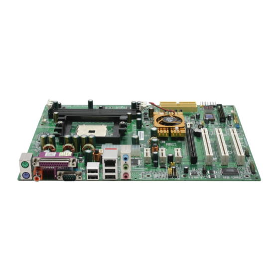
Installation Section 3 INSTALLATION Mainboard Layout Note: Depending on the model you purchased, some components are optional and may not be available. Page 3-1... -
Page 17: Easy Installation Procedure
Installation Easy Installation Procedure The following must be completed before powering on your new system: 3-1. CPU Installation 3-2. Jumper Settings 3-3. System Memory 3-4. Expansion Slots 3-5. Device Connectors 3-1 CPU Installation <Figure 2> <Figure 1> Step 1 Step 2 Open the socket by raising the actuation Align pin 1 on the CPU with pin 1 on lever. - Page 18 Installation <Figure 3> <Figure 4> Step 3 Step 4 Close the socket by lowering and Insert the heatsink as shown above. locking the actuation lever. Press the clips in the direction of the arrows shown in Figure 4 to secure the Apply thermal compound to the top of assembly to the CPU socket.
-
Page 19: Jumper Settings
Installation 3-2 Jumper Settings JCMOS: Clear CMOS data Jumper If the CMOS data becomes corrupted or you forgot the supervisor or user password, clear the CMOS data to reconfigure the system back to the default values stored in the ROM BIOS. Settings: 1-2: Normal (Default) 2-3: Clear CMOS... -
Page 20: System Memory Configuration
Installation 3-3 System Memory Configuration Memory Layout The mainboard accommodates three PC2100/PC2700/PC3200 184-pin DIMMs (Dual In-line Memory Modules): • Supports up to 3.0GB of 266/333/400MHz DDR SDRAM. • Supports unbuffered DIMM configurations defined in JEDEC DDR DIMM specification. <Figure 6> DDR DIMM 1 DDR DIMM 2 DDR DIMM 3... -
Page 21: Expansion Slots
Installation 3-4 Expansion Slots PCI-E Slots The mainboard is equipped with three PCI-E*1 compliant with PCI Express 1.0a. PCI-E VGA Slots The elongated PCI-E*16 is intended for PCI-E VGA card installation. PCI-E Slots PCI Slots PCI-E VGA Slot The mainboard is equipped with three PCI Slots PCI slots. -
Page 22: Device Connectors
Installation 3-5 Device Connectors The I/O back panel for this mainboard is shown below. When installing the mainboard into the computer case, use the bundled I/O shield to protect this back panel. RJ45 Parallel Port PS/2 Mouse PS/2 Keyboard S/PDIF-out COM1 S/PDIF-out USB2.0 x 4 ports... - Page 23 Installation Floppy Controller Connector This connects to the floppy disk drive. IDE1/IDE2:Ultra DMA-100/133 Primary/Secondary IDE Connector This mainboard is equipped with 2 IDE connectors IDE1 IDE2 to support up to 4 ATA-100/133 IDE drives. It supports PIO and DMA mode operations for maximum data transfer rate of 133MB/sec per channel.
- Page 24 Installation CFPA: Front Panel Audio Connector When the jumpers are removed this connector can be used for front panel audio. The front panel phone jack should have “normal close” switch. Without phone plug inserted, the rear panel audio is enabled. With phone plug inserted, the rear panel audio will be disabled.
- Page 25 Installation GAME1: Game/MIDI connector This port works well with any application that is compatible with the standard PC joystick. J1CY J1CX J1B1 J1B2 J2CX MIDI_In J2B2 J2B1 MIDI_Out J2CY COM2: Serial Port Connector The serial port can be used with modems, serial printers, remote display terminals, and other serial device.
- Page 26 Installation C1394-1 / C1394-2 : (Optional) IEEE 1394a (FireWire) Connectors This mainboard has 2 IEEE 1394a ports. To use these ports, you need to attach the bundled 1394 bracket to these headers. TPB+ +12V (Fused) TPA+ TPA- +12V (Fused) GND TPB- C1394-1C1394-2 CUSB3/CUSB4/CUSB5: Six USB 2.0 ports...
- Page 27 Installation CP80P: 80 Port Debug LED Provides two-digit POST code to show why the system fail to boot. Allows quick and easy optimization. 80 Port Debug 7-segment LED display (Refer to Appendix C for POST codes) PW-ON button and RESET button: (Optional) These buttons located onboard to turn on/off the system easily, especially while debugging or testing the system.
- Page 28 Installation CFP: Front Panel Connector HD_LED This LED will light up whenever the hard drive is being accessed. PWR_LED This connects to the power button of the system chassis This switch allows you to reboot without having to power off the system thus prolonging the life of the power supply or system.
-
Page 29: Power-On/Off (Remote)
Installation 3-6 Power-On/Off (Remote) This board has a 24-pin ATX and a 4-pin ATX12V power supply connector to support power supplies with Remote On/Off feature. The 4-pin ATX12V connector must be plugged in for the system to operate safely. The chassis power button should be connected to the mainboard front panel PW_ON header. - Page 30 Installation 3-8 ACPI S3 (Suspend To RAM) Function This mainboard supports the STR (Suspend To RAM) power management scheme by maintaining the appropriate power states in the DDR SDRAM interface signals. The power source to the DDR SDRAM is kept active during STR (ACPI S3).
- Page 31 Installation Page 3-16...
-
Page 32: Bios Setup
BIOS Section 4 BIOS SETUP Main Menu The ROM BIOS contains a built-in Setup program which allows user to modify the basic system configuration and hardware parameters. The modified data is stored in a battery-backed CMOS, so that data will be retained even when the power is turned off. -
Page 33: Standard Cmos Setup
BIOS The main menu displays all the major selection items. Select the item you need to reconfigure. The selection is made by moving the cursor (press any direction (arrow key ) to the item and pressing the ‘Enter’ key. An on-line help message is displayed at the bottom of the screen as the cursor is moved to various items which provides a better understanding of each function. -
Page 34: Advanced Bios Features
BIOS 4-2 Advanced BIOS Features Selecting the “ADVANCED BIOS FEATURES” option in the CMOS SETUP UTILITY menu allows users to change system related parameters in the displayed menu. This menu shows all of the manufacturer’s default values for the board. Pressing the [F1] key displays a help message for the selected item. - Page 35 BIOS Virus Warning During and after system boot up, any attempt to write to the boot sector or partition table of the hard disk drive halts the system and an error message appears. You should then run an anti-virus program to locate the virus. Keep in mind that this feature protects only the boot sector, not the entire hard drive.
-
Page 36: Advanced Chipset Features
BIOS System: The system will not boot and access to Setup will be denied unless the correct password is entered at the prompt. Setup: The system will boot, but access to Setup will be denied unless the correct password is entered at the prompt. HDD S.M.A.R.T. - Page 37 BIOS DRAM Configuration Scroll to DRAM Configuration and press <Enter>. The following screen appears: CAS# Latency (Tcl) Enables you to select the CAS latency time. The value is set at the factory depending on the DRAM installed. Do not change the values in this field unless you change specifications of the installed DRAM and DRAM clock from DRAM Timing Selectable.
-
Page 38: Integrated Peripherals
BIOS HT Frequency This item allows you select the Hyper Transport Frequency. Options: 1x, 2x, 3x, 4x, 5x. (1x-->200MHz, 2x-->400MHz, 3x-->600MHz, 4x-->800MHz, 5x-->1000MHz) CPU Spread Spectrum Options: Disabled, Center Spread. SATA Spread Spectrum Options: Disabled, Down Spread. PCIE Spread Spectrum Options: Disabled, Down Spread. - Page 39 BIOS IDE Function Setup Scroll to IDE Function Setup and press <Enter>. The following screen appears: OnChip IDE Channel 0/1 The mainboard supports two channel of ordinary IDE interface and one channel of serial ATA interface. Select “Enabled” to activate each channel separately. If you do not use the onboard IDE connector, set the Onboard Primary (Secondary) PCI IDE to “Disabled”.
- Page 40 BIOS Onboard Device Scroll to Onboard Device and press <Enter>. The following screen appears: Onchip USB Enables the USB controller. Options: Disabled, V1.1+V2.0, V1.1. USB Memory Select used memory space to record USB device information Options: Base memory, Shadow memory. USB Mouse Support Enable/Disable support for USB mouse under DOS.
- Page 41 BIOS Onboard Debug LED Enables the onboard Debug LED feature. Options: Enabled, Disabled. Onboard I/O Chip Setup Scroll to Onboard I/O Chip Setup and press <Enter>. The following screen appears: Onboard FDC Controller Select “Enabled” if you wish to use onboard floppy disk controller (FDC). If you install an external FDC or the system has no floppy drive, select “Disabled “in this field.
-
Page 42: Power Management Setup
BIOS ECP Mode USE DMA This field allows the user to select DMA1 or DMA3 for the ECP mode. Options: DMA1, DMA3. Game Port Address Select an address for the Game port. Options: 201, 209, Disabled. Midi Port Address Select an address for the Midi port. Options: 290, 300, 330, Disabled. - Page 43 BIOS ACPI Suspend Type This item allows you to select S1(Power-On-Suspend) or S3(Suspend-To-RAM) function. Options: S1(POS), S3(STR), S1&S3. Soft-Off by PBTN Use this to select your soft-off function. The default is Instant Off. Instant Off: Turns off the system instantly. Delay 4 Second : Turns off the system after a 4 second delay.
-
Page 44: Pnp/Pci Configuration
BIOS KB Power ON Password Press “Enter” to create a password that is required when you use the keyboard to power on the system. You must set the POWER ON Function to “Password” to be prompted for a password at power on. Hot Key Power ON Enables you to set a hot key combination to be used for powering on the system. - Page 45 BIOS Init Display First This item is used to select whether to initialize the VGA or PCI first when the system boots. Options: PCI Slot, PCIEx. Resources Controlled By Determines what controls system PNP/PCI resources. The default is Auto (ESCD). Manual: PNP Card’s resources are controlled manually.
-
Page 46: Pc Health Status
BIOS 4-7 PC Health Status Figure 8: PC Health Status Show PC Health in POST When this function is enabled the PC Health information is displayed during the POST (Power On Self Test). Options: Enabled, Disabled. ACPI Shutdown Temperature This is the temperature that the computer will turn off the power to combat the effects of an overheating system. - Page 47 BIOS Chipset Voltage The voltage level of the Chipset. DIMM Voltage The voltage level of the DRAM. Battery Voltage The voltage level of the battery. + 5V, 5V Standby The voltage level of the switching power supply. Smart Fan for CPU Temperature This item allows you set CPU fan temperature to smartly adjust the fan speeds for more efficient system operation.
-
Page 48: Power Bios Features
BIOS 4-8 POWER BIOS Features This page lets you adjust various parameters to obtain improved performance for overclocking. Warning: Overclocking requires expert knowledge and risks permanent damage to system components. We recommend you leave these parameters at their default values for proper operation. Figure 9: Frequency/Voltage Control CPU Frequency Enables you to increment the CPU’s clock generator at 1 MHz step. - Page 49 BIOS PCIE Clock Enables you to subtle tune the PCIE frequency at increments of 1MHz step. Options: 100 to 145 in 1MHz increments. AMD K8 Cool’n’Quiet Reduce the noise and heat from you PC when AMD’s Cool’n’Quiet technology is enabled. Options: Enabled, Disabled.
-
Page 50: Defaults Menu
BIOS Chipset Voltage This item allows you to adjust the chipset voltage. Options: 1.5V, 1.6V, 1.7V, 1.8V. We recommend that you leave this at the default value. 4-9 Defaults Menu Selecting “Defaults” from the main menu shows you two options which are de- scribed below Load Fail-Safe Defaults When you press <Enter>... -
Page 51: Supervisor/User Password Setting
BIOS 4-10 Supervisor/User Password Setting This function lets you set either Supervisor or User Password, or both, to prevent unauthorized changes to BIOS menus. supervisor password: full rights to enter and change options of the setup menus. user password: only enter but no rights to change options of the setup menus. - Page 52 BIOS 4-11 Exiting BIOS Save & Exit Setup Pressing <Enter> on this item asks for confirmation: Save to CMOS and EXIT (Y/N)? Y Pressing “Y” stores the selections made in the menus in CMOS – a special section of memory that stays on after you turn your system off. The next time you boot your computer, the BIOS configures your system according to the Setup selections stored in CMOS.
- Page 53 BIOS Page 4-22...
-
Page 54: Raid Configuration
RAID Configuration Section 5 RAID CONFIGURATION Introduction This section gives a brief introduction on RAID-related background knowledge and a general procedure to setup RAID system on this mainboard. RAID Basics RAID (Redundant Array of Independent Disks) is a method of combining two or more hard disk drives into one logical unit known as a RAID array. - Page 55 RAID Configuration RAID 0 (Striping) RAID 0 reads and writes sectors of data interleaved between multiple drives. If any disk member fails, it affects the entire array. The disk array data capacity is equal to the number of drive members times the capacity of the smallest member. The striping block size can be set from 4KB to 64KB.
-
Page 56: Nvidia Raid Features
RAID Configuration nVidia RAID Features The nVidia RAID solution uses the nForce4 series chip as a RAID controller, which is a 2-channel S-ATA and 1-channel ATA133 solution. Listed below are the main features and benefits of nVidia RAID: • Support two S-ATA hard disk drives. •... -
Page 57: Enable Raid Function
RAID Configuration Enable RAID Function For any RAID controller, the general procedure to enable RAID function are shown below: Note: If you are not installing O/S into the RAID disks, you may skip Step 2 & Step3. Step 1: Create RAID Array RAID arrays are created using the RAID controller’s BIOS utility. - Page 58 RAID Configuration Step 2: Prepare driver floppy When installing Windows XP/2000/NT4.0 into any RAID disk, the O/S setup will require a floppy disk containing the RAID driver. This step will show you how to prepare this driver floppy. There are 2 methods to prepare this floppy: Method 1 1.
- Page 59 RAID Configuration 1)Insert the bundled CD into the CD-ROM drive. 2)When the main menu appears, click on the RAID driver corresponding to the RAID controller you have configured in Step 1. See driver installation in section 6 for more details. Note: For information on using the software utility, refer to the user guide in the bundled CD.
-
Page 60: Driver Installation
Drivers Installation Section 6 DRIVER INSTALLATION Easy Driver Installation Once the operating system has been installed, you need to install the drivers for the mainboard. Please select: Auto Installation Method 1 Manual Installation Please install SP1 for Windows XP before installing nForce driver >>... -
Page 61: Realtek Sound Manager Quick User Guide
Drivers Installation Realtek Sound Manager Quick User-guide for ALC655 Š Introduction To obtain the best performance from your audio system, run the "Sound Manager" utility to adjust the settings to suit your needs. This section of the manual is intended to provide a quick user-guide to setup "Sound Manager". For more detailed information, refer to "Sound Manager manual"... - Page 62 Drivers Installation Equalizer: <Figure 3> 3. There are 10 bands of equalizer control, check "ON" when you want to adjust the equalizer. Speaker Configuration: <Figure 4> 4. This page displays the mainboards's phone jack function when a corresponding audio mode (no. of speaker) is selected. Figure 4 above shows the phone jack setup for 2 channel mode.
- Page 63 Drivers Installation Speaker Test: <Figure 5> 5. To test the speaker , select the “Speaker Test” page and click directly on the speakers shown on the screen. This board is equipped with Jack Sensing capability. If an audio device is plugged into the wrong connector, a warning message will appear to remind users to check the connection.
- Page 64 Drivers Installation Connector Sensing: <Figure 7> 7. EZ-Connection shows the result of the detection. “Audio Connector” column reflects the settings used in the "Speaker Configuration" page. “Current Connection” column shows the type of device detected. If the results do not match, an exclamation mark will appear on the right side. Connector Sensing: <Figure 8>...
- Page 65 Drivers Installation HRTF Demo: <Figure 9> 9. This page lets you test the HRTF 3D Positional Audio features. Microphone: <Figure 10> 10. The “Noise Suppression” feature uses software to reduce background delay microphone recording. Page 6-6...
- Page 66 Drivers Installation General: <Figure 11> ALC655 11. This page displays information regarding the audio hardware and software. To remove "Sound Manager" icon from Windows Task bar, uncheck "Show icon in system tray". Page 6-7...
- Page 67 Drivers Installation Realtek Sound Manager Quick guide for ALC850 (for high-end model only) Š Introduction To obtain the best performance from your audio system, run the "Sound Manager" utility to adjust the settings to suit your needs. This section of the manual is intended to provide a quick user-guide to setup "Sound Manager".
- Page 68 Drivers Installation Speaker Configuration: <Figure 14> 3. This page displays the mainboards's phone jack function when a corresponding audio mode is selected. Figure 3 above shows the phone jack setup for 8 channel mode. HRTF Demo: <Figure 15> 4. This page lets you test the HRTF 3D Positional Audio features. Page 6-9...
- Page 69 Drivers Installation General: <Figure 16> 5. This page displays information regarding the audio hardware and software. To remove "Sound Manager" icon from Windows Task bar, uncheck "Show icon in system tray". SPDIF: <Figure 17> 6. This page shows S/PDIF-In function on your system. S/PDIF-In: a.
- Page 70 Drivers Installation This board is equipped with Jack Sensing capability. If an audio device is plugged into the wrong connector, a warning message will appear to remind users to check the connection. Connector Sensing: <Figure 18> 7. Push "Start" button to start the sensing. Please remember to terminate all audio applications before starting the sensing.
- Page 71 Drivers Installation Connector Sensing: <Figure 20> 9. After closing EZ-Connector, this page will show the latest connector status as above. Microphone Effect: <Figure 21> 10. The “Noise Suppression” feature uses software to reduce background delay microphone recording. Page 6-12...
-
Page 72: Appendix
Appendix Appendix A A-1 Update Your System BIOS Download the xxxxx.EXE file corresponding to your model from our website to an empty directory on your hard disk or floppy. Run the downloaded xxxxx.EXE file and it will self extract. Copy these extracted files to a bootable floppy disk. Note: The floppy disk should contain NO device drivers or other programs. - Page 73 Appendix 5. Key in File Name to save previous BIOS to file. XXXX XXXXX xxxxx.bin xxxxx.bin 6. To confirm and proceed, please key in [Y] to start the programming. XXXX XXXXX xxxxx.bin xxxxx.bin 7. The BIOS update is finished. XXXX XXXXX xxxxx.bin F10 : Exit...
-
Page 74: Nvidia Raid Bios Utility
Appendix Appendix B B-1 NVIDIA RAID BIOS Utility Power-on the system and wait for the RAID BIOS Setting utility message on the screen. Press the ”F10” key to enter its BIOS configuration utility. Using the Define a New Array Window If necessary, press the tab key to move from field to field until the appropriate field is highlighted. - Page 75 Appendix To designate a free disk to be used as a RAID array disk, 1) Tab to the Free Disks section. The first disk in the list is selected 2) Move it from the Free Disks block to the Array Disks block by pressing the rightarrow key (->...
- Page 76 Appendix Use the arrow keys to select the array that you want to set up, then press Enter. The Array Detail window appears. The Array Detail window shows information about the array that you selected, such as Striping Block used, RAID Mode, Striping Width, Disk Model Name, and disk capacity.
- Page 77 Appendix...
-
Page 78: Post Codes
Appendix Appendix C C-1 POST CODES POST (hex) DESCRIPTION Test CMOS R/W functionality. Early chipset initialization: - Disable shadow RAM - Disable L2 cache (socket 7 or below) - Program basic chipset registers Detect memory - Auto-detection of DRAM size, type and ECC. - Auto-detection of L2 cache (socket 7 or below) Expand compressed BIOS code to DRAM Call chipset hook to copy BIOS back to E000 &... - Page 79 Appendix Detect CPU information including brand, SMI type (Cyrix or Intel) and CPU level (586 or 686). 19-1Ah Reserved Initial interrupts vector table. If no special specified, all H/W interrupts are directed to SPURIOUS_INT_HDLR & S/W interrupts to SPURIOUS_soft_HDLR. Reserved Initial EARLY_PM_INIT switch.
- Page 80 Appendix Test 8259 functionality. Reserved 45-46h Reserved Initialize EISA slot Reserved Calculate total memory by testing the last double word of each 64K page. Program writes allocation for AMD K5 CPU. 4A-4Dh Reserved Program MTRR of M1 CPU Initialize L2 cache for P6 class CPU & program CPU with proper cacheable range.
- Page 81 Appendix Reserved Initialize floppy controller Set up floppy related fields in 40:hardware. 70-72h Reserved (Optional Feature) Enter AWDFLASH.EXE if : -AWDFLASH is found in floppy drive. -ALT+F2 is pressed Reserved Detect & install all IDE devices: HDD, LS120, ZIP, CDROM….. Reserved Detect serial ports &...
- Page 82 User’ User’ s s s s s User’ User’ User’ Manual Manual Manual Manual Manual nVIDIA nVIDIA nForce nVIDIA nForce nForce nForce4 4 4 4 4 4X 4X mainboard for AMD mainboard for AMD mainboard for AMD mainboard for AMD nVIDIA nVIDIA nForce...
Need help?
Do you have a question about the EP-8NPAJ and is the answer not in the manual?
Questions and answers