Table of Contents
Advertisement
User'
User' s s s s s
User'
User'
User'
Manual
Manual
Manual
Manual
Manual
nVIDIA
nVIDIA
nForce2 Ultra 400 (nForce2 SPP)
nForce2 Ultra 400 (nForce2 SPP)
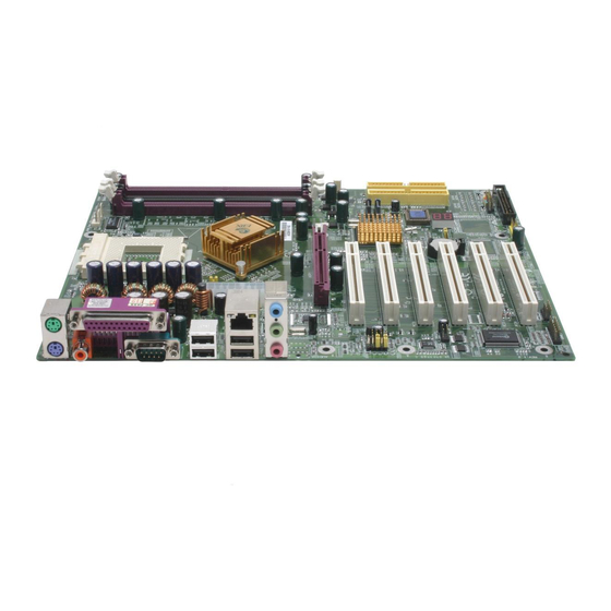
nVIDIA nForce2 Ultra 400 (nForce2 SPP)
nVIDIA
nVIDIA
nForce2 Ultra 400 (nForce2 SPP)
nForce2 Ultra 400 (nForce2 SPP)
mainboard for AMD Socket A processor
mainboard for AMD Socket A processor
mainboard for AMD Socket A processor
mainboard for AMD Socket A processor
mainboard for AMD Socket A processor
TRADEMARK
All products and company names are trademarks or registered
trademarks of their respective holders.
These specifications are subject to change without notice.
Manual Revision 3.0
November 06, 2003
Advertisement
Table of Contents


Need help?
Do you have a question about the nForce2 Ultra 400 and is the answer not in the manual?
Questions and answers