NCR 7454 User Manual
Retail terminal
Hide thumbs
Also See for 7454:
- Hardware user's manual (180 pages) ,
- User manual (174 pages) ,
- Site preparation manual (68 pages)

Related Manuals for NCR 7454


Summary of Contents for NCR 7454
- Page 1 NCR 7454 Retail Terminal Release 2.1 Hardware User’s Guide 18004 B005-0000-1256 Issue G...
- Page 2 NCR, therefore, reserves the right to change specifications without prior notice. All features, functions, and operations described herein may not be marketed by NCR in all parts of the world. In some instances, photographs are of equipment prototypes. Therefore, before using this document, consult with your NCR representative or NCR office for information that is applicable and current.
-
Page 3: Safety Warnings
Doing so may result in peripheral or system damage. Warning: The NCR 7454 must be mounted securely to prevent a hazard. It must be installed in accordance with local building codes. - Page 4 Peripheral Usage This terminal should only be used with peripheral devices that are certified by the appropriate safety agency for the country of installation (UL, CSA, TUV, VDE) or those which are recommended by NCR Corporation. Environmental Consciousness NCR is demonstrating its concern for the environment by designing an...
- Page 5 NCR 7454 Retail Terminal Site Preparation Guide (B005-0000-1257) • NCR 7454 Retail Terminal Software User’s Guide (B005-0000-1259) • NCR 7401/7454 Retail Terminal Parts Identification Manual (B005-0000-1072) • NCR 7401/7454 Retail Terminal Diagnostics and Troubleshooting Guide (B005-0000-1101) • NCR FitClient Software User’s Guide (B005-0000-1235)
-
Page 7: Table Of Contents
Wireless LAN Communications.......1-10 Universal Serial Bus ...........1-11 Serial Ports ............1-12 Hardware Monitor ..........1-13 PCI Expansion Header........1-13 IDE Header ............1-13 Audio..............1-13 Magnetic Stripe Reader........1-14 Touch Screen Controller ........1-14 Processor Board Connectors ......1-14 Flash Disk ............1-15 NCR Retail Specific Hardware ......1-15 Board BIOS ............1-18... - Page 8 BIOS Upgrades............1-19 Operator Display.............1-21 LCD Adapter Board ...........1-21 LCD Backlight Inverter Module .......1-22 Touch Screen ............1-22 NCR 7454 Integrated Customer Display .....1-23 NCR 5973 International VFD Customer Display1-24 Table Top Mount ..........1-24 16" High Post Mount ..........1-24 Features................1-25 Magnetic Stripe Reader ..........1-25 Printer Options............1-26...
- Page 9 7166 Printer............2-7 7194 Printer............2-8 7196 Printer............2-9 2214 Printer............2-10 Installing a Remote Customer Display ....2-11 7454-K453 Remote Customer Display .....2-11 5972-1100 Remote Customer Display ....2-13 5973 International VFD Customer Display..2-15 Installing a High-Post Integrated Customer Display..............2-17 Installing a Cash Drawer ........2-23 Installing a Second Cash Drawer .....2-24...
- Page 10 viii Installing a Serial Mouse ..........2-34 Guidelines for Calibrating the Touch Screen ....2-35 Calibration Procedure ..........2-35 Summary ..............2-37 Out-of-Box Failures ............2-37 Chapter 3: Setup Introduction..............3-1 Entering Setup Without a Keyboard ......3-1 Entering Setup Using a Keyboard ......3-2 How to Select Menu Options ........3-2 Restoring Factory Settings ........3-3 Setup Menus (Pentium) ..........3-4 Main Menu..............3-4...
- Page 11 Power Savings.............3-21 Fixed Disk ............3-23 Video ..............3-23 IDE Drive/PCI Bus Monitoring .......3-23 Boot Menu Options..........3-24 System Boot Sequence........3-24 Continuous POST ..........3-24 Exit Menu Options..........3-25 BIOS Default CMOS Values (Pentium)....3-26 Main Values............3-26 Advanced Values..........3-28 I/O Device Configuration .........3-28 PCI Configuration ..........3-29 Interrupts (Pentium)..........3-30 Memory Map (Pentium) ........3-31 Setup Menus (Pentium III/Celeron)......3-32...
- Page 12 Set Supervisor/User Password ......3-54 Diskette Access ...........3-55 Fixed Disk Boot Sector ........3-55 Password on Boot ..........3-56 Power Menu Options ..........3-57 Power Savings.............3-57 IDE Drive Monitoring ........3-59 PCI Bus Monitoring..........3-59 Video Power State Control........3-59 Boot Menu Options..........3-60 Exit Menu Options..........3-61 BIOS Default CMOS Values (Pentium III/Celeron)..............3-62 Main Values............3-62 Advanced Values..........3-63...
- Page 13 Recovery Software ..........4-20 OS Recovery from a Larger Disk Image.....4-21 Chapter 5: BIOS Updating Procedures Introduction..............5-1 Prerequisites ..............5-1 Updating Procedures..........5-2 BIOS Crisis Recovery ............5-3 Recovery Procedures ..........5-5 Cable/Connector Pin-Out Information......5-8 Chapter 6: NCR 7454 4x20 Customer Display Introduction..............6-1 Viewing Area.............6-1 Diagnostics..............6-2...
- Page 14 Character Set ..............6-3 Page 1 – International...........6-3 Page 2 – Japanese ..........6-4 Page 3 – Code Page 850........6-5 Command Descriptions..........6-6 Structure/Logic Description ........6-6 Host/Retail VFD Command Interface....6-6 Reset Display............6-8 Erase Display............6-8 Invalid Command ..........6-8 Set Diagnostic State ..........6-9 Set Display State On..........6-9 Set Low Power State On ........6-10 Enable Cursor............6-10 Disable Cursor.............6-10...
- Page 15 Installing the Windows 95 Drivers ....B-19 7454-F072 RS-232 Port (Dual) ........B-20 Installation Procedures.......... B-21 7454-K040 (8 MB) 7454-F041 (32 MB) Flash Disk ..B-23 Installation Procedures.......... B-23 Installing the Chip ..........B-23 Setting the BIOS Parameter ......B-24 Installing the Driver ..........
- Page 16 Installation Procedures.......... B-25 Usage Restrictions..........B-26...
- Page 17 Revision Record Issue Date Remarks Sept 00 First issue (separated 7401 and 7454 sections out of B005-0000-1069) Oct 00 Added new motherboard with Intel Pentium III/ Celeron processors Feb 01 Updated to Release 2.0 Removed hardware service information from this...
- Page 18 NCR is not responsible for any radio or television interference caused by unauthorized modification of this equipment or the substitution or attachment of connecting cables and equipment other than those specified by NCR.
-
Page 19: Declaration Of Conformity
Model Number 100-120 V/200-240 V, 2.0 A/1.0 A, 50-60 Hz Electrical Ratings (Input) NCR Corporation, 1700 South Patterson Boulevard, Dayton, OH 45479, USA, declares that the equipment specified above conforms to the referenced EU Directives and Harmonized Standards. EU Directive... -
Page 21: Chapter 1: Product Overview
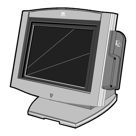
Housed in an integrated, compact cabinet, the 7454 supports a complete set of peripherals. The major hardware features of the 7454 are a flat panel display with touch screen input and LAN connectivity, plus optional magnetic stripe reader, scanner, stereo audio, and wireless LAN. -
Page 22: Serial Number/Model Number Label
To view the label, tilt the Core Module and remove the cable cover. Note: The serial number is repeated on the non-MSR side of the Core Module. Class/Model Serial Number 7454-2002-M007 50-32758815 Tracer Number 50-000077 Date Manufactured Mfg Date : 06/29/98... -
Page 23: Hardware Modules
Chapter 1: Product Overview Hardware Modules Base Unit • Processor Board − Intel Pentium or Pentium-class processor ® ® − SVGA chipset − MPEGII chipset − 32 MB RAM on board − 4 MB Video Memory − 1 MB Flash BIOS (not CMOS) −... -
Page 24: Hardware Options
Chapter 1: Product Overview • POS Connector Board − Cash drawer port (supports two drawers via a Y-cable) − Internal parallel port (dedicated to the optional customer display) • 12.1-Inch Operator Display - capacitive or resistive touch LCD, available in active matrix models •... - Page 25 2113 Cash Drawer (modular) − 2189 Cash Drawer (modular) − 2260 Cash Drawer (modular) − Dual cash drawer cable • 7454 Printers: − 7158 Thermal Receipt/Impact Printer − 7194 Thermal Receipt Printer − 7196 Thermal Receipt Printer − 2214 Thermal Fiscal Printer −...
-
Page 26: Terminal Components Not Supported
Chapter 1: Product Overview Terminal Components not Supported It is important to note that the terminal does not support the following components. Not supported Alternative implementation CMOS for hard totals, logs, and Hard disk, flash disk, or server tallies storage Removable media, e.g., a flex LAN communication to an NT server disk... -
Page 27: System Configuration Diagram
PS/2 KBD 2 Optionally Powered 2336-K008 7194 7158 Processor Board Note: 7194 and 7158 are available in both RS-232 and USB. Ethernet POS Connector Board 5972/5973 Cust Disp Cash Dwr SVideo Audio 2336-K007 2nd Cash Drawer 2260/2189 7454-K453 (Y-Cable) 2113 18470a... -
Page 28: Hardware Module Descriptions
Chapter 1: Product Overview Hardware Module Descriptions Processor Board Processor/Chip Set The terminal uses an Intel architecture processor, which permits it to leverage existing software drivers and applications, as well as provide the greatest flexibility in choosing an operating system. This provides several other advantages: •... -
Page 29: Ethernet 10/100Base-T Lan Communications
100Base-T is wired identically to 10Base-T, except that the twisted pair cable must be Category 5 and the hubs must permit 100 or 10/100 MB/s operation. Although 10Base-T will operate on Category 3 twisted pair, or NCR “747” cable, an upgrade to Category 5 is required for 100Base-T. -
Page 30: Wireless Lan Communications
10 MB. In order to upgrade to 100MB/s, Category 5 cable and 100 or 10/100 hubs must be installed. NCR strongly recommends the use of Category 5 for all new cabling, even if the customer initially intends to run only 10Base-T. -
Page 31: Universal Serial Bus
Chapter 1: Product Overview 1-11 • Device drivers for the targeted operating system must exist. • Appropriate infrastructure (server support, Base Stations, Ceiling Antennas, etc) must be present in the installation site, and the maximum RF range of the wireless system must not be exceeded. Interoperability - While the 802.11 standard provides an interoperable protocol definition, there are vendor-specific extensions to the protocol that encourage users to stay with one supplier’s equipment. -
Page 32: Serial Ports
1-12 Chapter 1: Product Overview Serial Ports The Celeron Motherboard provides two RS-232 ports (9-pin D-shell connectors, Ports 1 and 2) directly on the Motherboard and supports two additional RS-232 ports. Ports 3 and 4 require an optional harness connection to the Motherboard. Ports 1 and 3 can be supplied with +12 V DC on Pin 9 when properly set up in the BIOS. -
Page 33: Hardware Monitor
Chapter 1: Product Overview 1-13 Hardware Monitor The hardware monitor generates an interrupt to the system whenever any of the internal voltages used by the system processor goes above or below the acceptable operating range. An interrupt is also generated when the temperature of the Processor exceeds safe levels. -
Page 34: Magnetic Stripe Reader
1-14 Chapter 1: Product Overview Magnetic Stripe Reader A 3-track MSR head is available as an option. The ISO card format is supported. When card data is read, an interrupt is generated. A software device driver for the MSR must be loaded in order to allow the application to process the data. -
Page 35: Flash Disk
. A 32-pin socket is provided for this feature. The ® flash disk must be installed and enabled in BIOS Setup. NCR Retail Specific Hardware The Processor Board contains logic that provides support for the custom retail interface. The logic controls the following features: •... - Page 36 1-16 Chapter 1: Product Overview An integrated retail specific feature of the processor is the cash drawer circuitry. The onboard circuitry internal to the board provides the control for two external cash drawers. A portion of the POS Board header (J6) is provided on the board to interface to the dual cash drawer connector.
- Page 37 Chapter 1: Product Overview 1-17 Power LED The Processor Board provides support for an external power LED through the onboard Motion/Power LED connector. This LED is controlled through the SMC 37C935 GPIO pins. Once the SMC chip is programmed to support the Power LED function on GPIO pin 13, the LED is turned “on”...
-
Page 38: Board Bios
1-18 Chapter 1: Product Overview Resolutions Supported Resolution Colors Max Vfreq 800x600x8bpp 85 Hz 800x600x16bpp 64 K 85 Hz 800x600x24bpp 16 M 85 Hz Colors Supported Resolution 256 Colors 65,000 Colors 16.7 M Colors (8-Bit) (16-Bit) (24-Bit) 800x600 512 K 1 MB 2 MB Board BIOS... -
Page 39: Bios Upgrades
Chapter 1: Product Overview 1-19 The Flash device is divided into four areas, as described below. System Address FLASH Memory Area F0000H FFFFFH 64 K Main BIOS EE000H EFFFFH 8 K System BIOS Reserved during boot ED000H EDFFFH 4 K Plug and Play ESCD Storage Area E0000H ECFFFH 52 K System/VGA BIOS Reserved during boot... - Page 40 1-20 Chapter 1: Product Overview Plug and Play The Processor BIOS also has a setup option to support the Windows runtime plug and play utilities. When this option is selected, only devices critical to boot are assigned resources by the BIOS. Device Node information is available for all devices to ensure compatibility with Windows 95.
-
Page 41: Operator Display
Chapter 1: Product Overview 1-21 Operator Display 18004 The 7454 is available with a 12.1-Inch TFT (active matrix) LCD. Contrast control is set by software, using a digital potentiometer on the Processor Board. The terminal does not have a user-accessible contrast adjustment. -
Page 42: Lcd Backlight Inverter Module
1-22 Chapter 1: Product Overview LCD Backlight Inverter Module An Inverter Board supplies power for the LCD Backlight, which is a separate module in the terminal. The inverter has a connector that receives power, ground, and a Backlight dimming signal from the Processor Board. -
Page 43: Ncr 7454 Integrated Customer Display
Chapter 1: Product Overview 1-23 NCR 7454 Integrated Customer Display The NCR 7454 Integrated Customer Display supports four lines of twenty 5x7 characters. It is available in a low profile or high-post model. 16949 The 7454 Retail Terminal also supports these remote customer displays: •... -
Page 44: Ncr 5973 International Vfd Customer Display
1-24 Chapter 1: Product Overview NCR 5973 International VFD Customer Display The NCR 5973 VFD (Vacuum Fluorescent Display) is an optional display device for the 7454 Retail Terminal. The VFD is available in models that have a combination of: •... -
Page 45: Features
Chapter 1: Product Overview 1-25 Features Magnetic Stripe Reader A single 3-track analog Magnetic Stripe Reader (MSR) is available as a feature, supporting ISO format cards. When the MSR is not desired, a filler piece for the MSR section is included to make the unit appear uniform. -
Page 46: Printer Options
1-26 Chapter 1: Product Overview Printer Options The sections that follow provide an illustration and brief description of the available printer options. 7158 Printer The 7158 Printer is extremely fast, quiet, and reliable point-of-sale device. It consists of two specialized printers in one compact package: a thermal printer on top that prints receipts, and an impact slip printer in front to print on forms and checks that you insert. -
Page 47: 7166 Printer
Chapter 1: Product Overview 1-27 7166 Printer The 7166 Printer is an extremely fast, quiet, and reliable point-of-sale printer. It consists of two specialized printers in one compact package: a thermal printer that prints receipts, and an impact slip printer. It receives its power from an external power supply, has a serial interface and a connector for cash drawers. -
Page 48: 7196 Printer
1-28 Chapter 1: Product Overview 7196 Printer The 7196 Printer is a high speed, high-resolution printer, capable of both text and graphics printing. It receives its power from an external power supply, has a serial interface and a connector for cash drawers. 17302 2214 Printer The 2214 Printer is a thermal fiscal printer that can issue tickets and... -
Page 49: Other Integrated Devices And Indicators
Chapter 1: Product Overview 1-29 Other Integrated Devices and Indicators Hard Disk Drive A 2.5" IDE hard disk is available to support Windows NT. The drive is the standard type that is used by notebook PCs. Reset Switch The Reset Switch is provided as a last resort to reboot the system if the software reset port mechanisms fail. -
Page 50: Pos Connector Board
1-30 Chapter 1: Product Overview POS Connector Board The POS Connector Board is a small daughter board that mounts directly on the Cash Drawer and Parallel Port header. Connectors on the edge of this board form a second connector row above the Processor Board connectors. -
Page 51: Power Ok Led
Chapter 1: Product Overview 1-31 Power/Status LED The LED power indicator indicates that power is present. The LED is green when the processor and BIOS are operating properly. The LED is mounted behind the front bezel on the same board as the motion sensor. -
Page 52: Power Supply
1-32 Chapter 1: Product Overview Power Supply The terminal uses an AC adapter for its power supply, concealed in the terminal mounting. The supply is inaccessible when the terminal is in the normal operation and mounting position to prevent tampering, and sealed to help protect against spills or other environmental hazards. -
Page 53: Usb Rs-232 Port Server
Chapter 1: Product Overview 1-33 USB RS-232 Port Server The USB RS-232 Port Server is an intelligent, stackable expansion module that connects to the terminal Universal Serial Bus (USB) port, providing high-speed RS-232 serial ports. 7454/7401 USB Port RS-232 Ports 16944... -
Page 54: Additional Pentium Iii Connectors
A connector can be added on Pentium III models to add two additional RS-232 ports. To add the ports, install the Dual RS-232 Port Kit (7454-F072) as described in the Feature Kits appendix. The following illustration shows the RS-232 Connector, which is part of the Dual RS-232 Port Kit, installed on the Connector Row Bracket. -
Page 55: Chapter 2: Hardware Installation
Hardware Installation Chapter 2: Introduction The terminal is fully assembled at the factory. This chapter explains the mounting options and how to connect optional hardware components to the terminal. Installation Summary The terminal should be removed from the shipping packaging and visual checks made to verify the correct hardware configuration. -
Page 56: Installation Restrictions
AC power. This can result in system or printer damage. Warning: The 7454 must be mounted securely to prevent a hazard. It must be installed in accordance with local building codes. The post or wall on which the unit is mounted should be able to withstand four... -
Page 57: Connecting The Cables
Chapter 2: Hardware Installation Connecting the Cables Tilt Mount cable connectors are located on the underside of the Core Module, under a cable cover. Accessing the Cable Connectors 1. Tilt the display to access the cable connectors. Cable Cover Thumb Screw 15968 2. -
Page 58: Routing The Cables
Chapter 2: Hardware Installation Routing the Cables The 7454 has three places to secure cables to the base of the unit by using a cable tie wrap. Remove the power supply cover or customer display from the base of the unit, two thumb screws on bottom rear, and use a tie wrap to secure the Ethernet cable to one of the provided molded cable tie holders on the base. -
Page 59: Identifying The Cable Connectors
IRDA (not used) Microphone COM 2 (optional) RS-232 USB 1 (COM 3 & 4) Parallel USB 2 19107 Note: COM1 and COM3 are powered ports. Note: The COM3 & COM4 RS-232 ports require the Dual RS-232 Port Kit (7454-F072) feature... -
Page 60: Installing Peripherals
Chapter 2: Hardware Installation Installing Peripherals Installing a Transaction Printer 7158 Printer 1. Connect the Printer Interface Cable to the RS-232 Connector on the printer, located on the underside of the printer. Cash Drawer Power Connector Printer Connector RS232 17333 2. -
Page 61: 7166 Printer
Chapter 2: Hardware Installation 7166 Printer 1. Connect the Printer Interface Cable to the RS-232 Connector on the printer, located on the underside of the printer. Printer Connector RS232 Cash Drawer Power Connector 17332 2. Connect the other end of the printer cable to one of the RS-232 ports (non-powered) on the terminal. -
Page 62: 7194 Printer
Chapter 2: Hardware Installation 7194 Printer 1. Connect the Printer Interface Cable to the RS-232 Connector on the printer, located on the underside of the printer. Cash Drawer Connector Power Connector RS-232 Connector 16632 2. Connect the other end of the printer cable to a USB port or one of the RS-232 (non-powered) ports on the terminal. -
Page 63: 7196 Printer
Chapter 2: Hardware Installation 7196 Printer 1. Connect the Printer Interface Cable to the RS-232 Connector on the printer, located on the underside of the printer. Printer Connector RS232 Cash Drawer Power Connector 17331 Connect the other end of the printer cable to one of the RS-232 (non-powered) ports on the terminal. -
Page 64: 2214 Printer
2-10 Chapter 2: Hardware Installation 2214 Printer 1. Connect the Printer Interface Cable to the RS-232 Connector on the back of the printer. RS-232 Connector Printer Interface Cable 18543 2. Connect the other end of the Printer Interface Cable to an RS-232 port (non-powered) on the terminal. -
Page 65: Installing A Remote Customer Display
Installing a Remote Customer Display The terminal supports three high-post remote customer displays. The mounting configuration is the same and appearance is similar: • 7454-K453 Remote Customer Display (4x20 characters, VFD) • 5972-1000 Remote Customer Display (2x20 characters, VFD) •... - Page 66 2-12 Chapter 2: Hardware Installation 3. Secure the Mounting Plate with 4 screws provided. Mounting Plate 4 Holes 0.40 mm (0.16 in.) Diameter 76 mm (3 in.) 16671 4. Connect the Display Cable to the Customer Display port on the terminal.
-
Page 67: 5972-1100 Remote Customer Display
Chapter 2: Hardware Installation 2-13 5972-1100 Remote Customer Display 16257 1. Place the Display Mount on the desired surface within 4 meters (13 feet) of the host terminal. 2. Determine if the cable should be routed down through the mounting surface or if it should be run on top of the surface. 3. - Page 68 5972 Display Cable Parallel I/F Adapter Cable 497-0405676 - 4 M 497-0411000 - 0.6 M 1416-C278-0040 1416-C472-0006 Customer 7454 Cust. Display Display Port Power Brick 16291a 5. Connect the Parallel I/F Adapter Cable to the Customer Display port on the terminal.
-
Page 69: 5973 International Vfd Customer Display
Chapter 2: Hardware Installation 2-15 5973 International VFD Customer Display (4) Screws 14528 1. Place the Display Mount on the desired surface within 4 meters (13 feet) of the host terminal. 2. Determine if the cable should be routed down through the mounting surface or if it should be run on top of the surface. - Page 70 2-16 Chapter 2: Hardware Installation 3. Connect the 5973 Parallel Cable to the Customer Display port on the terminal. Customer Display 15969b...
-
Page 71: Installing A High-Post Integrated Customer Display
Chapter 2: Hardware Installation 2-17 Installing a High-Post Integrated Customer Display The 7454 Integrated Customer Display supports four lines of twenty 5x7 characters. This is the same display module that is used with the low-profile integrated display. 16713... - Page 72 (5972-F039) The standard Poser Supply Cover on the 5953-F022 Remote Table Top Mount does not support attachment of an integrated NCR 7454 4 x 20 Customer Display. In order to mount an integrated display you need to install 5972-039, which includes: 1.
- Page 73 Chapter 2: Hardware Installation 2-19 Installation Procedure 1. Route the cable (display connector end) up through the Power Supply Cover, Display Post, and Top Bracket. This is a tight fit and the connector has to be angled in order to make it though the openings.
- Page 74 2-20 Chapter 2: Hardware Installation 4. Connect the cable to the a) Remove the Integrated Display Bracket (2 screws). b) Connect the cable to the 2 x 20 VFD Assembly. c) Replace the Integrated Display Bracket. 4 x 20 VFD Assembly Integrated Display Bracket Phillips PH Screw (4-24 x 0.625)
- Page 75 Chapter 2: Hardware Installation 2-21 6. Install the Nylon Hold Plug in the Power Supply Cover, locking the post in place. The slot permits the display to be rotated to personal preference. Nylon Hole Plug 7454 Customer Display Connector 16948...
- Page 76 Press in on both sides of the cover and lift it up in the back to remove it. 20049 Press in on Both Sides Screws (2) 8. Install the Customer Display and Cover assembly onto the 7454 (2 screws). 16713 9. Connect the Display Cable to the Customer Display connector on the terminal.
-
Page 77: Installing A Cash Drawer
Chapter 2: Hardware Installation 2-23 Installing a Cash Drawer 1. Place the cash drawer in the desired location, within cable length of the terminal. 16269 2. Connect the cash drawer cable to the terminal cash drawer connector. Cash Drawer 15969c Note: The Cash Drawer can optionally be connected to the printer. -
Page 78: Installing A Second Cash Drawer
2-24 Chapter 2: Hardware Installation Installing a Second Cash Drawer The terminal supports a 2-drawer configuration with a Y-cable (1416-C372-0006). 1. Place the cash drawer in the desired location, within cable length of the terminal. 2. Connect the Y-cable to the terminal cash drawer connector. Dual Cash Drawer Y-Cable 1416-C372-0006 16270... -
Page 79: Mounting The 7454
Chapter 2: Hardware Installation 2-25 Mounting the 7454 A Tilt Mount terminal can be installed on a flat horizontal surface or a flat vertical surface. Table-Top Mount Wall Mount 16429... -
Page 80: Wall Mounting A Tilt Mount
2-26 Chapter 2: Hardware Installation Wall Mounting a Tilt Mount To install the Tilt Mount on a flat vertical surface, use the K533 Wall Mount Bracket Kit . 1. Secure the Wall Plate to the wall with lag screws (4) into the studs or with hardware of similar strength. -
Page 81: Finalizing The Installation
Chapter 2: Hardware Installation 2-27 Finalizing the Installation After the hardware installation has been completed, the terminal can be powered up to finalize the installation. The operating system, along with platform modifications, is pre-installed. The following sections list the steps involved to complete the system installation for each of the Gold Disk operating systems. -
Page 82: Completing The Os Installation (Win95)
1. When the terminal boots it enters the Windows setup routine. Note: When installing Win98 on terminals with early Processor Boards (7454-22xx) there are few differences in the procedure as follows: a) The terminal starts the Add New Hardware Wizard. -
Page 83: Setting Auto-Logon (Winnt Terminal)
Chapter 2: Hardware Installation 2-29 Setting Auto-Logon (WinNT Terminal) Since the client does not have a keyboard it is desirous to have it logon automatically. 1. Create a default user account that you want to use to logon to the client(s). - Page 84 2-30 Chapter 2: Hardware Installation d) Add the new user to the group. You need to do Administrators this in order to be able to later turn off the auto-logon function. e) Select to close the Group Membership box. f) Select to create the account.
- Page 85 Chapter 2: Hardware Installation 2-31 5. Create a new string value to permit auto logon for the default user. Select the menu, select and then select Edit String Value 6. Name the new entry AutoAdminLogon...
- Page 86 2-32 Chapter 2: Hardware Installation 7. Edit the string value. With the new entry selected, select the Edit menu and then select . Enter the value 1 for auto-logon. A Modify value of 0 sets it to no auto-logon. 8. Select to set the value.
- Page 87 Chapter 2: Hardware Installation 2-33 11. Create a new string value to contain the password for the default user. Select the menu, select and then select Edit String Value 12. Name the new entry DefaultPassword 13. Edit the string value. With DefaultPassword selected, select the Edit menu and then select .
-
Page 88: Installing A Serial Mouse
2-34 Chapter 2: Hardware Installation Installing a Serial Mouse Follow these steps to install a Serial Mouse on the terminal. 1. Edit the boot.ini file, which is located in the root of the C drive. a. Open Windows NT Explorer b. -
Page 89: Guidelines For Calibrating The Touch Screen
Chapter 2: Hardware Installation 2-35 Guidelines for Calibrating the Touch Screen The following guidelines should be observed for calibrating the touch screen. • Calibration should be done at time of installation • Recalibrate the touch screen when the system is installed at its final location. - Page 90 2-36 Chapter 2: Hardware Installation • If cursor is not stable, or false touches are suspected, run the Noise Check Utility from the Touchware Control Panel (Windows) or from the Microcal (DOS) program. Choose the recommended frequency (the one with the lowest noise level). This should also be done if the touch screen is still not calibrated after one attempt to recalibrate it.
-
Page 91: Summary
The customer is responsible for restoring operating system software and/or customer-specific data onto replacement disks sent to repair a failed or damaged disk in the field. NCR provides recovery tools for the operating system and platform software. -
Page 93: Chapter 3: Setup
Note: An external alphanumeric keyboard is not required to run the BIOS CMOS Setup Utility, but a keyboard makes the setup easier. Note: The Setup Menus in this chapter reference NCR 7401/7454 BIOS Version 1.5.0.4 (Pentium) and NCR 7401/7452/7453/7454/7455 BIOS Version 2.1.2.0 (Pentium III). -
Page 94: Entering Setup Using A Keyboard
Chapter 3: Setup c) Using the same method as above, touch the circle near the upper-right corner of the screen. You should receive a Successful Calibration message and then the PhoenixBIOS Setup Utility should come up. d) Select the setup parameters by touching the controls at the bottom of the screen. -
Page 95: Restoring Factory Settings
Chapter 3: Setup Restoring Factory Settings To automatically reset all values to their default settings for the current screen, press F9. The terminal will automatically load BIOS default CMOS values for boot up. To reset all BIOS settings to their default settings go to the Exit menu, press F9, select either Save Changes &... -
Page 96: Setup Menus (Pentium)
Chapter 3: Setup Setup Menus (Pentium) Main Menu PhoenixBIOS Setup Utility Main Advanced Security Power Boot Exit Main System Time: [10:54:34] Item Specific Help System Date: [7/21/1998] Legacy Diskette A: [1.44/1/25 Mb, 3½"] Legacy Diskette B: [Disabled] Primary Master (2163MB) Primary Slave [None] Secondary Master... -
Page 97: Primary Master
Chapter 3: Setup Primary Master After installing a new hard drive, the system should automatically detect the drive. If this is not done automatically and you need to configure the IDE Adapter. Perform the following steps: 1. Move the cursor to the Primary Master option and press Enter. A sub-menu appears for the IDE drive. -
Page 98: Memory Cache
Chapter 3: Setup Memory Cache This option is used to specify your terminal to cache system memory. Note: Cache memory must be present on the Processor Board in order to use this option. To set the memory cache, perform the following steps: 1. - Page 99 Chapter 3: Setup Cache System BIOS 1. Move the cursor to the Cache System BIOS area: option. 2. Press Enter and then select the desired setting from the drop-down menu. Disabled Enabled 3. Set the other options on this menu as desired. Select Help for more information.
-
Page 100: Advanced Menu
Chapter 3: Setup Advanced Menu PhoenixBIOS Setup Utility Advanced Main Advanced Security Power Boot Exit Setup Warning Item Specific Help Setting items on this menu to incorrect values may cause your system to malfunction. I/O Device Configuration Multiple ROM Menu Plug &... - Page 101 Chapter 3: Setup Local Bus Adapter This option is used to enable the integrated local bus IDE adapter. 1. Move the cursor to the Local Bus IDE Adapter option. 2. Press Enter and then select the desired setting from the drop-down menu.
- Page 102 3-10 Chapter 3: Setup Mode This option is used to set the mode for serial port B. 1. Move the cursor to the Mode option. Normal IrDA ASK-IR 2. Press Enter and then select the desired setting from the drop-down menu.
- Page 103 Chapter 3: Setup 3-11 Mode This option is used to set the mode for the parallel port. 1. Move the cursor to the Mode option. Output only Bi-directional 2. Press Enter and then select the desired setting from the drop-down menu.
- Page 104 3-12 Chapter 3: Setup MSR Address This option is used to select the memory address range used by the Magnetic Stripe Reader. 1. Move the cursor to the MSR Address option. Disabled CC00-CDFF CE00-CFFF D000-D1FF 2. Press Enter and then select the desired setting from the drop-down menu.
- Page 105 Chapter 3: Setup 3-13 1. Move the cursor to the Selectable ROM x option. Disabled Enabled 2. Press Enter and then select the desired setting from the drop-down menu. • Disabled – do not load ROM • Enabled – load ROM in next boot Note: Due to available space limitations (48 K), only enable the required ROMs.
- Page 106 3-14 Chapter 3: Setup Reset Configuration Data 1. Move the cursor to the Reset Configuration Data option. 2. Press Enter and then select the desired setting from the drop-down menu. • Select Yes if you want to clear the System Configuration Data. PS/2 Mouse This option is used to configure the parallel port.
-
Page 107: Large Disk Access
Chapter 3: Setup 3-15 Large Disk Access 1. Move the cursor to the Large Disk Access option. Other 2. Press Enter and then select the desired setting from the drop-down menu. • Select DOS for Windows NT O/S. • Select Other if you are using UNIX , Novell NetWare , or... -
Page 108: Pci Configuration
3-16 Chapter 3: Setup PCI Configuration From the Advanced Menu, move the cursor to the PCI Configuration option and press Enter. The options on this menu are used to configure peripherals. PhoenixBIOS Setup Utility System Time: [12:34:00] Item Specific Help Exit Submenu System Date: [02/29/1997]... - Page 109 Chapter 3: Setup 3-17 PCI/PNP ISA UMB Region Exclusion These options are used to reserve specific upper memory blocks for use by legacy ISA devices. 1. Move the cursor to the PCI/PNP ISA UMB Region Exclusion option and press Enter to display the options. PhoenixBIOS Setup Utility System Time: [12:34:00]...
- Page 110 3-18 Chapter 3: Setup PCI/PNP ISA IRQ Resource Exclusion These options are used to reserve specific IRQs for use by legacy ISA devices. 1. Move the cursor to the PCI/PNP ISA IRQ Resource Exclusion option and press Enter to display the options. PhoenixBIOS Setup Utility System Time: [12:34:00]...
-
Page 111: Security Menu Options
Chapter 3: Setup 3-19 Security Menu Options PhoenixBIOS Setup Utility Security Main Advanced Security Power Boot Exit Supervisor Password Is: [Clear] Item Specific Help User Password Is: [Clear] Set Supervisor Password: [Enter] Set User Password: [Enter] Password on boot: [Disabled] Set Supervisor/User Password The Supervisor Password controls access to the setup utility. -
Page 112: Password On Boot
3-20 Chapter 3: Setup Password on Boot This option enables/disables the password entry on boot. Note: User Password must also be set. 1. Move the cursor to the Password on boot option and press Enter. 2. Press Enter and then select the desired setting from the drop-down menu. -
Page 113: Power Menu Options
Chapter 3: Setup 3-21 Power Menu Options PhoenixBIOS Setup Utility Power Main Advanced Security Power Boot Exit Power Savings: [Disabled] Item Specific Help Standby Timeout: [Off] Auto Suspend Timeout: [Off] Fixed Disk: [Enabled] Video: [Enabled] IDE Drive 0 Monitoring: [Disabled] IDE Drive 1 Monitoring: [Disabled] IDE Drive 2 Monitoring: [Disabled] IDE Drive 3 Monitoring: [Disabled]... - Page 114 3-22 Chapter 3: Setup Customized Mode The Customized Mode permits user-defined settings. 1. Move the cursor to select the Standby Timeout option. 2. Press Enter and then select the desired setting from the drop-down menu. 1 Minute 2 Minutes 3 Minutes 4 Minutes 6 Minutes 8 Minutes...
-
Page 115: Fixed Disk
Chapter 3: Setup 3-23 Fixed Disk This option is used to enable/disable power management of the hard disk during Standby and Suspend. To set this option, perform the following steps: 1. Move the cursor to the Fixed Disk option. 2. Press Enter and then select the desired setting from the drop-down menu. -
Page 116: Boot Menu Options
3-24 Chapter 3: Setup Boot Menu Options PhoenixBIOS Setup Utility Boot Main Advanced Security Power Boot Exit 1. [LANDesk ® Service Agent II] Item Specific Help 2. [Hard Drive] Continuous POST: [Disabled] System Boot Sequence This is a list of devices that the terminal uses to boot the system. To change the sequence of the devices, perform the following steps: 1. -
Page 117: Exit Menu Options
Chapter 3: Setup 3-25 Exit Menu Options PhoenixBIOS Setup Utility Exit Main Advanced Security Power Boot Exit Exit Saving Changes: Item Specific Help Exit Discarding Changes Load Setup Defaults Discard Changes Save Changes Exit Saving Changes Exit after writing all changed option values to CMOS memory. Exit Discarding Changes Exit without saving changed option values to CMOS memory. -
Page 118: Bios Default Cmos Values (Pentium)
3-26 Chapter 3: Setup BIOS Default CMOS Values (Pentium) The following are the BIOS default CMOS values for the terminal. Note: When installing a new BIOS from the CD, the Processor Board type is automatically detected and the correct BIOS is automatically installed. - Page 119 Chapter 3: Setup 3-27 IDE Primary Slave Type None IDE Secondary Master Type None IDE Secondary Slave Type None Enabled Memory Cache Enabled Cache System BIOS area Disabled Cache Video BIOS area 640 K System Memory 31744 K Extended Memory Disabled Power Savings Standby Timeout...
-
Page 120: Advanced Values
3-28 Chapter 3: Setup Disabled IDE Drive 3 Monitoring Disabled PCI Bus Monitoring Boot sequence 1. LANDesk ® Service Agent II 2. Hard Drive Continuous POST Disabled Advanced Values I/O Device Configuration Primary Local Bus IDE adapter Auto Serial port A Auto Serial port B Normal... -
Page 121: Pci Configuration
Chapter 3: Setup 3-29 Auto PS/2 Mouse Large Disk Access Mode Secured Setup Configurations PCI Configuration ISA Graphics Device Installed Available (all) PCI/PNP ISA UMB Region Exclusion... -
Page 122: Interrupts (Pentium)
Reserved, Keyboard buffer full Reserved, Cascade interrupt Serial Port 2 Serial Port 1 User available Reserved, Floppy Parallel Port 1 Real Time Clock NCR Motion, Thermal interrupt Windows Sound System/USB Touch Screen Reserved, Math coprocessor On-board IDE (available if IDE is disabled) -
Page 123: Memory Map (Pentium)
BIOS Reserved (currently available as UMB) D0000-DFFFF 64 K Available HI DOS memory CE000-CFFFF Flash Disk (optional) CC000-CDFFF NCR Trigantor MSR (optional) C0000-CBFFF 48 K Onboard video BIOS A0000-BFFFF 128 K Reserved for video memory 9FC00-9FFFF Extended BIOS Data (moveable by... -
Page 124: Setup Menus (Pentium Iii/Celeron)
3-32 Chapter 3: Setup Setup Menus (Pentium III/Celeron) Main Menu PhoenixBIOS Setup Utility Main Main Advanced Security Power Boot Exit System Time: [10:54:34] Item Specific Help System Date: [05/25/2000] Legacy Diskette A: [1.44/1/25 Mb, 3½"] Legacy Diskette B: [Disabled] Primary Master (2168MB) Primary Slave [None]... -
Page 125: Legacy Diskette
Chapter 3: Setup 3-33 Legacy Diskette The terminal does not have a flex disk drive. Therefore this option is unused, even though Setup defaults to 1.44 MB, 3 ½". Primary Master After installing a new hard drive, the system should automatically detect the drive. -
Page 126: Advanced Menu
3-34 Chapter 3: Setup Advanced Menu PhoenixBIOS Setup Utility System Time: [12:34:00] Item Specific Help Advanced Main Advanced Security Power Boot Exit System Date: [02/29/1997] Installed O/S: [Win95] Item Specific Help Secured Setup Configurations Reset Configuration Data: [No] Cache Memory PS/2 port: [Touchscreen] USB Port 2:... -
Page 127: Cache Memory
Chapter 3: Setup 3-35 Cache Memory Note: Cache memory must be present on the Processor Board in order to use this option. This option specifies your terminal’s cache memory. 1. Move the cursor to the Cache Memory option, press Enter and the following sub-menu appears. - Page 128 3-36 Chapter 3: Setup Cache System BIOS 1. Move the cursor to the Cache System BIOS area: option. 2. Press Enter and then select the desired setting from the drop-down menu. uncached Write Protect 3. Set the other options on this menu as desired. Select Help for more information.
-
Page 129: I/O Device Configuration
Chapter 3: Setup 3-37 I/O Device Configuration Move the cursor to the I/O Device Configuration option, press Enter and the following sub-menu appears. PhoenixBIOS Setup Utility Exit Main I/O Device Configuration Item Specific Help Serial port A: [Auto] Scanner Power: [Auto] Serial port B: [Auto]... - Page 130 3-38 Chapter 3: Setup Scanner Power (Port A) This option sets the mode of the scanner power pin on COM 1 when on +12 V is present on pin 9. 1. Move the cursor to the Scanner Power option. 2. Press Enter and then select the desired setting from the drop-down menu.
- Page 131 Chapter 3: Setup 3-39 Parallel Port This option configures the parallel port. 1. Move the cursor to the Parallel Port option. 2. Press Enter and then select the desired setting from the drop-down menu. Disabled Enabled Auto • Disabled – no configuration •...
-
Page 132: Floppy Disk Controller
3-40 Chapter 3: Setup Fdc On Lpt This option enables/disables the primary floppy on the parallel port. 1. Move the cursor to the Fdc On Lpt option. 2. Press Enter and then select the desired setting from the drop-down menu. Disabled Enabled Floppy Disk Controller... - Page 133 Chapter 3: Setup 3-41 Base I/O Address (Port C) This option sets the base I/O address for serial port C. 1. Move the cursor to the Base I/O address option. 2. Press Enter and then select the desired setting from the drop-down menu.
- Page 134 3-42 Chapter 3: Setup Scanner Power (Port C) This option sets the mode of the scanner power pin on COM 1 when on +12 V is present on pin 9. 1. Move the cursor to the Scanner Power option. 2. Press Enter and then select the desired setting from the drop-down menu.
- Page 135 Chapter 3: Setup 3-43 Base I/O Address (Port D) This option sets the base I/O address for serial port D. 1. Move the cursor to the Base I/O address option. 2. Press Enter and then select the desired setting from the drop-down menu.
- Page 136 3-44 Chapter 3: Setup Mode (Port D) This option configures the COM D communication mode. 1. Move the cursor to the Mode option. 2. Press Enter and then select the desired setting from the drop-down menu. Other RS-232 Disk-On-Chip Address This option selects the memory address range used by the Disk-On- Chip.
-
Page 137: System Monitors
Chapter 3: Setup 3-45 MSR Address This option selects the memory address range used by the Magnetic Stripe Reader. 1. Move the cursor to the MSR Address option. 2. Press Enter and then select the desired setting from the drop-down menu. -
Page 138: Multiple Rom Menu
3-46 Chapter 3: Setup Multiple ROM Menu This option is used to load/unload specific ROMs the next time the system is started. 1. Move the cursor to the Multiple ROM Menu option and press Enter. 2. Move the cursor to the Selectable ROM x option. Disabled Enabled 3. -
Page 139: Beep Error Codes
Chapter 3: Setup 3-47 Beep Error Codes The Beep Error Codes option enables/disables beep codes on error(s). Move the cursor to Beep Error Codes, press Enter, and select On or Off. Large Disk Access 1. Move the cursor to the Large Disk Access option. Other 2. -
Page 140: Advanced Chipset Control
3-48 Chapter 3: Setup Advanced Chipset Control Move the cursor to the Advanced Chipset Control option, press Enter and the following sub-menu appears. PhoenixBIOS Setup Utility Exit Submenu Main Advanced Chipset Control Item Specific Help Graphics Aperture: [64 MB] Enable memory gap: [Disabled] ECC Config: [Disabled]... - Page 141 Chapter 3: Setup 3-49 Graphics Aperture This option selects the size of the graphics aperture for the AGP device. 1. Move the cursor to the Graphics Aperture option. 2. Press Enter and then select the desired setting from the drop-down menu.
-
Page 142: Ecc Config
3-50 Chapter 3: Setup ECC Config Use this option only if all memory in the system supports ECC (x72). 1. Move the cursor to the ECC Config option. 2. Press Enter and then select the desired setting from the drop-down menu. - Page 143 Chapter 3: Setup 3-51 Default Primary Video Adapter This selects the type of video card used for the boot display device. 1. Move the cursor to the Default Primary Video Adapter option. 2. Press Enter and then select the desired setting from the drop-down menu.
- Page 144 3-52 Chapter 3: Setup PCI/PNP IRQ Resource Exclusion This option reserves specific IRQs for use by a legacy device. 1. Move the cursor to the PCI/PNP IRQ Resource Exclusion option. 2. Press Enter and select the desired IRQ from the drop-down menu. 3.
- Page 145 Chapter 3: Setup 3-53 QuickBoot Mode This option decreases boot time by skipping some tests while booting. 1. Move the cursor to the QuickBoot Mode option. 2. Press Enter and then select the desired setting from the drop-down menu. Disabled Enabled Continuous POST This option is enables POST to repeat in a loop until canceled.
-
Page 146: Security Menu Options
3-54 Chapter 3: Setup Security Menu Options PhoenixBIOS Setup Utility Main Advanced Security Power Boot Exit Security Supervisor Password Is: [Clear] Item Specific Help User Password Is: [Clear] Set Supervisor Password: [Enter] Set User Password: [Enter] Diskette access: [Supervisor] Fixed disk boot sector: [Normal] Password on boot: [Disabled] Set Supervisor/User Password... -
Page 147: Diskette Access
Chapter 3: Setup 3-55 Diskette Access Access to the diskette can be limited to the supervisor or access can also be given to the user. 1. Move the cursor to the Diskette Access option and press Enter. 2. Press Enter and then select the desired setting from the drop-down menu. -
Page 148: Password On Boot
3-56 Chapter 3: Setup Password on Boot This option enables/disables the password entry on boot. Note: User Password must also be set. 1. Move the cursor to the Password on boot option and press Enter. 2. Press Enter and then select the desired setting from the drop-down menu. -
Page 149: Power Menu Options
Chapter 3: Setup 3-57 Power Menu Options PhoenixBIOS Setup Utility System Time: [12:34:00] Item Specific Help System Date: [02/29/1997] Power Main Advanced Security Power Boot Exit Power Savings: [Disabled] Item Specific Help Standby Timeout: [Off] Auto Suspend Timeout: [Off] IDE Drive 0 Monitoring: [Disabled] IDE Drive 1 Monitoring: [Disabled] IDE Drive 2 Monitoring: [Disabled] IDE Drive 3 Monitoring: [Disabled]... - Page 150 3-58 Chapter 3: Setup Customized Mode The Customized Mode permits user-defined settings. 1. Move the cursor to select the Standby Timeout option. 2. Press Enter and then select the desired setting from the drop-down menu. 1 Minute 2 Minutes 3 Minutes 4 Minutes 6 Minutes 8 Minutes...
-
Page 151: Ide Drive Monitoring
Chapter 3: Setup 3-59 IDE Drive Monitoring This option enables/disables activity on the IDE device to keep the system awake. 1. Move the cursor to the IDE Drive x Monitoring option. 2. Press Enter and then select the desired setting from the drop-down menu. -
Page 152: Boot Menu Options
3-60 Chapter 3: Setup Boot Menu Options PhoenixBIOS Setup Utility Boot Main Advanced Security Power Boot Exit Hard Drive Item Specific Help ATAPI CD-Rom Drive Removable Devices Intel ® Boot Agent Version 4.0.17 This screen provides a list of devices that the terminal uses to boot the system. -
Page 153: Exit Menu Options
Chapter 3: Setup 3-61 Exit Menu Options PhoenixBIOS Setup Utility Main Advanced Security Power Boot Exit Exit Saving Changes Item Specific Help Exit Discarding Changes Load Setup Defaults Discard Changes Save Changes Exit Saving Changes Exit after writing all changed option values to CMOS memory. Exit Discarding Changes Exit without saving changed option values to CMOS memory. -
Page 154: Bios Default Cmos Values (Pentium Iii/Celeron)
3-62 Chapter 3: Setup BIOS Default CMOS Values (Pentium III/Celeron) The following are the BIOS default CMOS values for the workstation. Note: When installing a new BIOS from the CD, the Processor Board type is automatically detected and the correct BIOS is automatically installed. -
Page 155: Advanced Values
Chapter 3: Setup 3-63 32 Bit I/O Disabled Transfer Mode Standard Ultra DMA Mode Disabled Secondary Master None Type Auto Multi-Sector Transfers Disabled LBA Mode Control Disabled 32 Bit I/O Disabled Transfer Mode Standard Ultra DMA Mode Disabled Secondary Slave None Type Auto... - Page 156 3-64 Chapter 3: Setup Cache Video BIOS Write Protect Cache Base 0-512 K Write Back Cache Base 512K-640 K Write Back Cache Extended Memory Write Back Cache A000-AFFF Disabled Cache B000-BFFF Disabled Cache C800-CBFF Disabled Cache CC00-CFFF Disabled Cache D000-D3FF Disabled Cache D400-D7FF Disabled...
- Page 157 Chapter 3: Setup 3-65 Serial Port C Enabled Mode Normal Base I/O Address Interrupt IRQ 11 Scanner Power Auto Serial Port D Enabled Base I/O Address Interrupt IRQ 11 Mode RS-232 Disk-On-Chip Address CE00 - CFFF MSR Address CC00 - CDFF MSR Interrupt System Monitors +12 V Status...
- Page 158 3-66 Chapter 3: Setup Parallel CD-ROM Boot Disabled On-board Intel PXE Enabled WaveLAN ROM Disabled WaveLAN PXE Rom Disabled Selectable ROM 6 Disabled Selectable ROM 7 Disabled Selectable ROM 8 Disabled Selectable ROM 9 Disabled Selectable ROM 10 Disabled Selectable ROM 11 Disabled Selectable ROM 12 Disabled...
- Page 159 Chapter 3: Setup 3-67 D000 – D3FF Available D400 – D7FF Available D800 – DBFF Available DC00 - DFFF Available PCI/PNP IRQ Resource Exclusion IRQ 3 Available IRQ 4 Available IRQ 5 Available IRQ 7 Available IRQ 9 Available IRQ 10 Available IRQ 11 Available...
-
Page 160: Security Values
3-68 Chapter 3: Setup Security Values Clear Supervisor Password Is Clear User Password Is Press ENTER Set Supervisor Password Press ENTER Set User Password Supervisor Diskette Access Normal Fixed Disk Boot Sector Disabled Password on Boot Power Values Disabled Power Savings Standby Timeout Auto Suspend Timeout Disabled... -
Page 161: Interrupts (Pentium Iii/Celeron)
Serial Port 1 Serial Ports 3 and 4 Reserved, Floppy Parallel Port 1 Real Time Clock NCR Thermal interrupt/PII4 SMBus Audio Mouse (available if disabled) Reserved, Math coprocessor On-board IDE (available if IDE is disabled) On-board IDE (available for MSR if IDE is disabled) -
Page 162: Memory Map (Pentium Iii/Celeron)
BIOS Reserved (currently available as UMB) D0000-DFFFF 64 K Available HI DOS memory CE000-CFFFF Flash Disk (optional) CC000-CDFFF NCR Trigantor MSR (optional) C0000-CAFFF 42 K Onboard video BIOS A0000-BFFFF 128 K Reserved for video memory 9FC00-9FFFF Extended BIOS Data (moveable by... -
Page 163: Chapter 4: Operating System Recovery
It is also possible to perform a BIOS update using a network connection. Refer to the NCR FitClient Software User's Guide for information about that procedure. Prerequisites The following are required on the 7454 in order to perform a BIOS update using a CD. • Bootable CD-ROM drive (2336-K007) •... -
Page 164: Updating Procedures
Parallel Connector Power Connector Parallel Connector 18250 Note: The parallel port on the 7454 is the Customer Display port. Therefore, if your terminal is configured with a Customer Display, you must temporarily disconnect it in order to use the CD-ROM drive. - Page 165 Chapter 4: Operating System Recovery 3. Apply power to the terminal so the CD-ROM drive can be opened. 4. Insert the CD that contains the operating system image. 7454 Model Software CD LPINs Win2000 WinNT Win98 Win95 7454-22xx D370-0489-0100 D370-0433-0100 D370-0444-0100 D370-0442-0100 D370-0445-0100...
-
Page 166: Completing The Os Installation (Winnt)
Chapter 4: Operating System Recovery If No is selected: • The Ghost error file is displayed before rebooting only if Ghost aborts. Caution: If the error file is displayed, the batch file pauses for user input before rebooting. You may use Ctrl-C to cancel out of the batch file if you want to see the error file again, but nothing should be done that writes to the hard disk before rebooting. -
Page 167: Completing The Os Installation (Win98)
1. When the terminal boots it enters the Windows setup routine. Note: When installing Win98 on terminals with early Processor Boards (7454-22xx) there are few differences in the procedure as follows: a) The terminal starts the Add New Hardware Wizard. -
Page 168: Completing The Os Installation (Win95)
Chapter 4: Operating System Recovery Completing the OS Installation (Win95) The system automatically reboots when the image recovery is complete and starts the software installation. This installation also installs most of the additional software and drivers that are included in the disk image. -
Page 169: Gold Disk Contents
• The NCR OS Recovery image can only be used to recover or update systems with licenses procured from NCR. -
Page 170: Ncr 7454-32Xx Win2000 Operating System Recovery Software
7454-32xx Windows 2000 Operating System Recovery Software provides the means of restoring the operating system to the hard disk of a 7454 POS terminal. The bootstrap program (di_intel.bsd) and disk recovery boot image (di_intel.bid) are downloaded to the target terminal over the network and restore the hard disk to the preinstalled state as shipped from the factory. - Page 171 • ‘Enable PME’ (in Intel Proset utility) set to ‘Hardware Default’ • Disabled game port • Enabled DMA • Set color to 16 bit Note: This product should only be used on 7454 terminals with a Microsoft Windows 2000 license...
-
Page 172: Ncr 7454-22Xx Win2000 Operating System Recovery Software
4-10 Chapter 4: Operating System Recovery NCR 7454-22xx Win2000 Operating System Recovery Software (LPIN: D370-0489-0100) Installs the following software: • Microsoft Windows 2000 Professional with Service Pack 1 installed • Microsoft Internet Explorer 5.0 installed (version 5.00.3103.1000) • Chips and Technologies 69000 Assailant Video driver installed (version 2.46 Beta) -
Page 173: Ncr 7454-32Xx Nt Operating System Recovery Software
(LPIN: D370-0483-0100) 7454-32xx NT Operating System Recovery Software provides the means of restoring the operating system to the hard disk of a 7454 POS terminal. The bootstrap program (di_intel.bsd) and disk recovery boot image (di_intel.bid) are downloaded to the target terminal over the network and restore the hard disk to the preinstalled state as shipped from the factory. - Page 174 Exposed to both EM and EM+ video chipsets • Installed SMI Control Panel • Installed Intel Proset utility • Enabled DMA • Muted Volume Line-In Note: This product should only be used on 7454 terminals with a Microsoft Windows NT license.
-
Page 175: Ncr 7454-22Xx Nt Operating System Recovery Software
Chapter 4: Operating System Recovery 4-13 NCR 7454-22xx NT Operating System Recovery Software (LPIN: D370-0433-0100) Installs the following software: • Microsoft Windows NT Workstation 4.0 with Service Pack 4a installed. Service Pack 6 included (but not installed) on the disk •... - Page 176 Preinstall the Product ID Number (PID) • Places the Gold Drive Part Number, Date Created, LPIN, and Version in Registry under: HKey-Local_Machine\Software\NCR\Gold Drive • Windows Installer (Version 1.1) installed • Removes the following key from the registry (as a current COM9...
-
Page 177: Ncr 7454-32Xx Win98 Operating System Recovery Software
(LPIN: D370-0481-0100) 7454-32xx Win98 Operating System Recovery Software provides the means of restoring the operating system to the hard disk of a 7454 POS terminal. The bootstrap program (di_intel.bsd) and disk recovery boot image (di_intel.bid) are downloaded to the target terminal over the network and restore the hard disk to the preinstalled state as shipped from the factory. - Page 178 Disabled game device and joystick • Set to High Color • ‘Enable PME’ (in Intel Proset utility) set to ‘Hardware Default’ • Muted the Volume Line-In Note: This product should only be used on 7454 terminals with a Microsoft Windows 98 license.
-
Page 179: Ncr 7454-22Xx Win98 Operating System Recovery Software
Chapter 4: Operating System Recovery 4-17 NCR 7454-22xx Win98 Operating System Recovery Software (LPIN: D370-0444-0100) Installs the following software: • Microsoft Windows 98 Second Edition installed • Microsoft Internet Explorer 5.0 installed • MicroTouch TouchWare Version 5.4 for Mouse Port software installed •... -
Page 180: Ncr 7454-32Xx Win95 Operating System Recovery Software
(LPIN: D370-0503-0000) 7454-32xx Windows 95 Operating System Recovery Software provides the means of restoring the operating system to the hard disk of a 7454 POS terminal. The bootstrap program (di_intel.bsd) and disk recovery boot image (di_intel.bid) are downloaded to the target terminal over the network and restore the hard disk to the preinstalled state as shipped from the factory. - Page 181 Exposed to both EM and EM+ video chipsets • Installed Intel Proset Utility • Disabled game device and joystick • Set color to 256 Note: This product should only be used on 7454 terminals with a Microsoft Windows 95 license.
-
Page 182: Ncr 7454-22Xx Win95 Operating System Recovery Software
4-20 Chapter 4: Operating System Recovery NCR 7454-22xx Win95 Operating System Recovery Software (LPIN: D370-0442-0000) Installs the following software: • Installs Win95 w/PID • Msdos.sys file edited to include the following parameter: Autoscan = 2 • IE5 installed • MicroTouch version 5.4 installed •... -
Page 183: Os Recovery From A Larger Disk Image
Chapter 4: Operating System Recovery 4-21 OS Recovery from a Larger Disk Image The following procedure should be used to restore an Operating System when the destination disk is smaller than the source image (i.e., OS Recovery was made on a 10 GB source disk, but is being recovered on a 4.3 GB drive). - Page 184 4-22 Chapter 4: Operating System Recovery 10. The directory that Ghost is now looking in should be Z: (if not, switch to Z). Select the file File name to load image from (nnnnnnn.gho) and press Enter 11. Select the and press Local destination drive Enter 12.
-
Page 185: Chapter 5: Bios Updating Procedures
BIOS Update procedure, you can use the method discussed later in this chapter in the BIOS Crisis Recovery section to recover the BIOS. Prerequisites The following are required on the 7454 in order to perform a BIOS update using a CD. • Bootable CD-ROM drive (2336-K007) •... -
Page 186: Updating Procedures
Connector Parallel Connector 18250 Note: The parallel port on the 7454 is the Customer Display port. Therefore, if your terminal is configured with a Customer Display, you must temporarily disconnect it in order to use the CD-ROM drive. 3. Apply power to the terminal so the CD-ROM drive can be opened. - Page 187 Chapter 5: BIOS Updating Procedures 6. Press at the screen prompt to enter the Setup Utility. 7. In the menu, select Advanced I/O Device Configuration 8. Verify that the is set to LPT 1 Mode 9. Go back to the menu, select Advanced Multiple ROM Menu...
-
Page 188: Bios Crisis Recovery
Parallel Dongle Forces BIOS recovery 497-0414184 POS Connector Board 7454 parallel port (not required if already present) Required Software Acquire the following software from NCR. NCR 74xx BIOS and BIOS Update Software LPIN: A370-0022-0100, Release 3.0 or later P/N: 497-0424310... -
Page 189: Recovery Procedures
Customer 16993 Display Note: The parallel connector on the 7454 terminal is used for the Customer Display. If the terminal is equipped with a Customer Display you must temporarily disconnect the display cable. If the terminal is not equipped with a Customer Display then it is likely that the terminal does not have a parallel connector and you will have to install the POS Connector Board. - Page 190 Chapter 5: BIOS Updating Procedures 2. Connect the two machines with the RS-232 cable. Use COM Port 1 on both machines (COM1 is next to the USB ports on the 7454). NCR 7454 RS-232 Cable Parallel I/F Cable Parallel Dongle 16991 3.
- Page 191 Chapter 5: BIOS Updating Procedures 8. Enter the update command: EMBflash [Enter] 9. Select the number for the 7454 terminal from the menu list: 1) 7454 2) 7401 3) 7452 4) 7453 5) 7455 6) 7460 7) 7451 8) 7456...
-
Page 192: Cable/Connector Pin-Out Information
Chapter 5: BIOS Updating Procedures Cable/Connector Pin-Out Information Parallel Dongle 25-Pin D-shell Receptacle (Viewed from wiring side) 19513 RS-232 Cable 9-Pin 9-Pin D-shell D-shell Receptacle Receptacle 19512... - Page 193 Chapter 5: BIOS Updating Procedures...
-
Page 195: Chapter 6: Ncr 7454 4X20 Customer Display
Chapter 6: Introduction This chapter defines the character sets and supported commands. The NCR 7454 4x20 Customer Display is IEEE 1284 Compatible and supports Extended Capability Parallel (ECP). Viewing Area The characters are arranged in 4 rows of 20 characters. Each character is a 5x7 dot matrix. -
Page 196: Diagnostics
Chapter 6: NCR 7454 4x20 Customer Display Diagnostics Power-Up Diagnostics occur soon after the hardware reset circuitry is released, or when a Reset Display command is received from the host software. When the hardware is powered down, all registers and memory are lost. -
Page 197: Character Set
Chapter 6: NCR 7454 4x20 Customer Display Character Set Page 1 – International... -
Page 198: Page 2 - Japanese
Chapter 6: NCR 7454 4x20 Customer Display Page 2 – Japanese... -
Page 199: Code
Chapter 6: NCR 7454 4x20 Customer Display Page 3 – Code Page 850... -
Page 200: Command Descriptions
Chapter 6: NCR 7454 4x20 Customer Display Command Descriptions Structure/Logic Description The Retail VFD firmware is comprised of operating system type services such as common subroutines, interrupt service routines, and data processing routines. Normally, the firmware is always active refreshing the Retail VFD to keep display data visible. The firmware will also act on interrupts due to host parallel communication. - Page 201 Chapter 6: NCR 7454 4x20 Customer Display Command Function Return Status/String 1B 01 Reset Display 1B 02 Erase Display 1B 03 Invalid Command 1B 04 Set Diagnostic State 1B 05 Set Display State On 1B 06 Set Low Power State On (Default)
-
Page 202: Reset Display
Chapter 6: NCR 7454 4x20 Customer Display Reset Display Format: 1B 01 Description: This command executes the power-down power-up diagnostic sequence. The BUSY line is set to active condition. The micro-controller test consists of a sum-check test on the ROM and a write/read test on the RAM. -
Page 203: Set Diagnostic State
Description: This state is exclusive from the On and Low Power states. This command causes the firmware to display the current NCR part number and firmware version of the device. For example, the current part number and firmware version of the device are 008-0221537 and V1.00.01) for two seconds and then step through each installed 256-... -
Page 204: Set Low Power State On
6-10 Chapter 6: NCR 7454 4x20 Customer Display Set Low Power State On Format: 1B 06 Description: This state is used to reduce Retail VFD power consumption and extend the life of the Retail VFD. Power is only removed from the VFD and the display will not be refreshed. -
Page 205: Set Screen Save Blank
Chapter 6: NCR 7454 4x20 Customer Display 6-11 Set Screen Save Blank Format: 1B 09 Description: This command is intended to preserve the life of the display hardware unit. The firmware maintains a five-minute timer that triggers this feature. The Screen Save feature can be disabled through a command from the host software. -
Page 206: Disable Screen Save Option
6-12 Chapter 6: NCR 7454 4x20 Customer Display Disable Screen Save Option Format: 1B 0C Description: The firmware will cease to keep time for the screen save activity from the host software and the display will neither go blank nor begin to walk due to inactivity from the host. -
Page 207: Move Cursor Left
Chapter 6: NCR 7454 4x20 Customer Display 6-13 Move Cursor Left Format: 1B 0F Description: Moves the cursor one position to the left. When the cursor is at the left end of the rows 2-4, it moves to the right end of the row above it. When the cursor is at the left end of the row 1, it moves to the right end of the row 4. -
Page 208: Move Cursor Down
6-14 Chapter 6: NCR 7454 4x20 Customer Display Move Cursor Down Format: 1B 12 Description: Moves the cursor down one line. When the cursor is on the 1-3, the cursor is moved to the same column on the next row. When the cursor is on the row 4, the cursor is moved to the same column on the row 1. -
Page 209: Brightness Adjustment
Chapter 6: NCR 7454 4x20 Customer Display 6-15 Brightness Adjustment Format: 1B 17 nn 01 ≤ nn ≤ 05 Range: Description: Adjusts the brightness of the entire display. Individual characters or display positions will not be adjusted. On power up, the default brightness setting is 5 (100%). -
Page 210: Display Esc Character
6-16 Chapter 6: NCR 7454 4x20 Customer Display Description: This command is a request for the Retail VFD to return an ASCII string with detailed product information. Display ESC Character (Not a supported command) Format: 1B 1B Description: This command is a request for the ESC character to be displayed to the current cursor position. -
Page 211: Appendix A: Cables
Cables Appendix A: Cable Index Corporate ID Part Number Description 1416-C041-0030 497-0008623 Ethernet 10/100BaseT 1416-C262-0040 497-0404832 2010 coin dispenser 1416-C266-0040 497-0407943 9-pin female to 9-pin female RS-232 1416-C266-0152 497-0409379 7193 RS-232 50' 9-pin female to 9- pin female 1416-C320-0030 006-8601011 Cord set –... - Page 212 Appendix A: Cables Corporate ID Part Number Description 1416-C373-0080 497-0409432 25' cable 1416-C374-0040 497-0409433 14' cable 1416-C408-0030 230-0113955 Power, SEV 1416-C409-0030 230-0113956 Power, UK rectangular 1416-C411-0030 006-1012224 Power, international 1416-C417-0040 497-0411815 Printer extender, 9-pin female to 25-pin female 1416-C418-0040 497-0411816 Printer extender, 25-pin male to 25-pin female 1416-C419-0030...
-
Page 213: Appendix B: Feature Kits
Feature Kits Appendix B: Kit Index Kit Number Part Number Description 2010-K020-V001 497-0414206 Coin tray 2126-K161-V001 603-6211364 C-3 till 2126-K302-V001 603-6211312 C-3 till, lid with lock (2188-K202-V001) 2189-K052-V002 497-0009697 Slip tray (7450 G13) 2189-K053-V002 497-0009695 Coin tray (7450 G13) 2189-K060-V001 497-0009209 Till 2 ½... - Page 214 Appendix B: Feature Kits Kit Number Part Number Description 2336-K030-V001 497-0417048 Coin cartridge – US 340403 2336-K031-V001 497-0417051 Coin cartridge – 1 dollar coin, US standard 340406 2336-K032-V001 497-0417053 Coin cartridge – Canadian 340405 2336-K033-V001 497-0417357 56 K modem, PCMCIA 2336-K455-V001 008-0221553 Remote 256x64 graphic VFD 2336-K600-V001 497-0414963...
- Page 215 Appendix B: Feature Kits Kit Number Part Number Description 2757-K145-V001 497-0414899 OAsys bump bar mounting bracket 2757-K150-V001 497-0423521 OAsys KDS base kit with AV1000 card 2757-K200-V001 497-0414900 OAsys video add-on kit 2757-K250-V001 497-0423522 OAsys KDS add-on kit with AV1000 card 2757-K300-V001 497-0414901 10 MB Ethernet card with software license...
- Page 216 Modular cash drawer – 2260 7453-K007-V001 497-0414767 Till with lid and lock 7453-K641-V003 497-0413391 Serial modems for 7161 and 7193 printers 7454-K005-V001 497-0424210 Modular cash drawer – midrange, gray 105, with anti-temper drawer flange 7454-K040-V001 497-0411474 8 MB flash disk...
-
Page 217: 7401-K060 Pcmcia Port (Dual
Installing the Dual PCMCIA Port 1. Remove the Back Panel from the Core Module as described in the 7454 Retail Terminal Hardware Service Guide. 2. Remove the Filler Plate from the Cabinet Back. 3. Remove the knockout from the sheet metal. - Page 218 Appendix B: Feature Kits 4. Install the PCMCIA Assembly. PCMCIA Bracket PCMCIA Assembly PCMCIA Connector 16871 a) Connect the PCMCIA Assembly card to the Processor Board. b) Secure the assembly with the hex screw. c) Install the PCMCIA Bracket. The bracket fits under the sheet metal extension and is secured with screws (2).
- Page 219 Appendix B: Feature Kits 5. Install the Antenna Cover and secure it with screws (2). Wireless Antenna Cover 16874...
-
Page 220: 2336-K033 Pcmcia Modem
Dual PCMCIA Port (7401-K060). Installing the PCMCIA Modem 1. Remove the Back Panel from the Core Module as described in the 7454 Retail Terminal Hardware Service Guide. 2. Remove the Antenna Cover (2 screws). Wireless Antenna Cover... - Page 221 Appendix B: Feature Kits 3. Insert the PCMCIA Modem into one of the PCMCIA slots. Wireless Antenna Cover PCMCIA Modem Cable PCMCIA Modem Route the cable between the cabinet and sheet metal. 16873 4. Connect the Modem Cable to the PCMCIA Modem. 5.
-
Page 222: Setting Up The Pcmcia Modem
B-10 Appendix B: Feature Kits Setting Up the PCMCIA Modem For 7454s with the Pentium III/Celeron running Windows NT, the following two options show how the system can be configured and what peripherals can be attached. Set-Up Option 1 Set the modem is to use IRQ5 and I/O Address 3E8. This option gives the user access to COM1 and COM2 (for use of scanner and printer), MSR, Disk-On-Chip, and Parallel Port. -
Page 223: Set-Up Option 2
Appendix B: Feature Kits B-11 Set-Up Option 2 Set the modem to use IRQ5 and I/O Address 3E8. This option gives the user access to both COM ports, Onboard LAN boot, and the parallel port. However, the MSR and Disk-On-Chip must be disabled. Bios Option Setting Default (Y / N) -
Page 224: 2336-K007 Cd-Rom Drive (External
Crisis Recovery and BIOS Update. It uses an industry standard parallel interface and functions similar to a regular CD-ROM. Note: The parallel port on the 7454 is the Customer Display port. Therefore, if your terminal is configured with a Customer Display, you must temporarily disconnect it in order to use the CD-ROM drive. -
Page 225: Hardware Installation
Appendix B: Feature Kits B-13 Hardware Installation 1. Connect the CD-ROM drive to the parallel port on the terminal (disconnect the Customer Display if applicable). 2. Connect the opposite end of the CD-ROM cable (end with the power connector pigtail) to the CD-ROM drive parallel connector. Parallel Connector Power Connector... -
Page 226: Using The Cd-Rom For Os Recovery And Bios Update
B-14 Appendix B: Feature Kits Set Parallel Port to Bi-directional Mode It is recommended that you configure the terminal parallel port to Bi- directional Mode. This will ensure error-free data transfer. Note: This is the default BIOS setting and may not be necessary to set. 1. -
Page 227: Installing The Cd-Rom Drivers For Windows Operation
Appendix B: Feature Kits B-15 Installing the CD-ROM Drivers for Windows Operation If you want to use the CD-ROM drive with Windows you must install the drivers manually. The drivers are located on the terminal hard disk. → 1. Select . - Page 228 B-16 Appendix B: Feature Kits 3. Select Install or Update BACKPACK Driver 4. Select to restart the computer. Finish...
-
Page 229: 2336-K008 Usb Rs-232 Port Server (4 Port
Appendix B: Feature Kits B-17 2336-K008 USB RS-232 Port Server (4 Port) This device provides four additional RS-232 ports via the terminal USB port. 16943 7454/7401 USB Port RS-232 Ports 16944... -
Page 230: Installation Procedures
B-18 Appendix B: Feature Kits Installation Procedures Connect the cable that is supplied with the kit to the terminal USB connector. Refer to the 7454 Retail Terminal Software User’s Guide for driver installation procedures. USB Connector 15969d Installing the Windows NT Drivers 1. -
Page 231: Installing The Windows 95 Drivers
Appendix B: Feature Kits B-19 Installing the Windows 95 Drivers 1. After connecting the USB cable the Update Device Driver Wizard dialog screen should appear. 2. Insert the Edgeport Driver disk into drive A. 3. Click on to initiate a floppy drive search for the updated Next driver device. - Page 232 B-20 Appendix B: Feature Kits 7454-F072 RS-232 Port (Dual) The Pentium III/Celeron Motherboard has two RS-232 ports (9-pin D- shell connectors, Com 1 and 2) directly on the board. The Dual RS-232 Port Kit is used to make two additional ports (Com 3 and 4) available.
- Page 233 Appendix B: Feature Kits B-21 Installation Procedures The Dual RS-232 Port kit contains an Interface Cable, a Dual RS-232 Cable and two screws. The following illustration shows the Connector Row Bracket with the the Interface Cable Connector (Com 3 and 4) installed.
- Page 234 B-22 Appendix B: Feature Kits 2. Plug the Interface Cable into connectors J23 and J24 on the Motherboard. Install in Connector Row Bracket Connect to J24 Connect to J23 19104 3. Use the screws provided to install the connector on the Connector Row Bracket.
-
Page 235: Installation Procedures
Appendix B: Feature Kits B-23 7454-K040 (8 MB) 7454-F041 (32 MB) Flash Disk The Flash Disk (Disk-on-Chip) is a solid state device that provides additional storage. It uses an industry standard IDE interface and functions similar to a regular hard disk. The device is located on the Processor Board. -
Page 236: Setting The Bios Parameter
B-24 Appendix B: Feature Kits Setting the BIOS Parameter 1. Power up the terminal. 2. Enter the PhoenixBIOS Setup Utility (refer to the Setup chapter). 3. Select the menu. Advanced 4. Select I/O Device Configuration 5. Verify that : is set to CE00-CFFF. Disk-On-Chip Address Installing the Driver 1. -
Page 237: 7453-K641 Serial Modem For 7194 Printer
Appendix B: Feature Kits B-25 7453-K641 Serial Modem for 7194 Printer With this kit the 7194 printer can be placed in a remote location, away from the terminal. The section provides details for installing this kit. RS-232 Extender Cable RS-232 Short Range Modem RS-232 Extender Cable 497-0411815 - 4 m 006-8602085... - Page 238 5. Set the switches on both modems to DTE, Printer, and CTRL. Usage Restrictions • The short modems must be used with the appropriate NCR cables. − 7194 Printer (497-0411815) − 7454 Terminal (497-0411815) •...
- Page 239 Index Command descriptions, 6-6 Diagnostics, 6-2 —A— Customer Display Command Descriptions Advanced power management, 1-20 Brightness Adjustment, 6-15 Audio, 1-13 Disable Character Blink, 6-12 Auto-Logon Disable Cursor, 6-10 Setting, 2-26 Disable Screen Save Option, 6-12 Display ESC Character, 6-16 —B— Enable Character Blink, 6-12 Enable Cursor, 6-10 BIOS crisis recovery, 5-5...
- Page 240 LAN status LEDs, 1-31 LCD adapter board, 1-21 Features/kits LCD backlight inverter module, 1-22 CD-ROM drive (2336-K007), B-12 Dual RS-232 Port (7454-F072), B-20 Dual RS-232 Port (7454-K072), B-20 —M— Flash disk (7454-K040), B-23 Modem (2336-K033), B-8 Magnetic stripe reader, 1-14, 1-17...
- Page 241 Index-3 POS connector board, 1-30 Entering without a keyboard, 3-1 Features, 1-4 Exit menu options, 3-25, 3-61 Power LED, 1-17 Fixed disk, 3-23 Power OK LED, 1-31 I/O device configuration, 3-8, 3-12, 3- Power supply 37, 3-45, 3-46, 3-47, 3-48 Description, 1-32 IDE drive/PCI bus monitoring, 3-23, 3- Power/status LED, 1-31...
- Page 242 Index-4 —V— —W— Video subsystem, 1-8 Wireless LAN communications, 1-10...
- Page 244 B005-0000-1256 June 2002 Printed on recycled paper...
Need help?
Do you have a question about the 7454 and is the answer not in the manual?
Questions and answers