JVC RM-LP25U Instructions Manual
Remote control panel
Hide thumbs
Also See for RM-LP25U:
- Instructions manual (28 pages) ,
- Instructions manual (28 pages) ,
- Instructions manual (28 pages)
Table of Contents
Advertisement
Quick Links
REMOTE CONTROL PANEL
RM-LP25U
Thank you for purchasing this JVC product.
Before beginning to operate this unit,please read
the instructions
carefully to ensure the best possible performance.
For Customer Use:
Enter below the Serial No. which is located on the
body.
Retain this information for future reference.
Model No.
Serial No.
INSTRUCTIONS
O P E
R A T
E
L O C
K
P A R
1
T
S C E
O F F
2
N E
F I L
F U L
E
L
3
B A R
S
N O R
P A R
4
M A
T
L
1 / 1 0
0
1 / 1 2
5
0
1 / 2 5
S P E
S H U
0
E D
T T E
0 d B
R
1 / 5 0
0
3 d B
1 / 1 0
0 0
6 d B
1 / 2 0
G A I
- 3 d
0 0
B
N
V A R
9 d B
I A B
- 6 d
L E
B
1 2 d
B
A L C
1 5 d
L E V
B
L O L
E L
U X
G A M
1 8 d
B
M A
V A R
I A B
L E
L E V
E L
L E V
E L
D E T
B L A
A I L
C O M
C K
P R E
K N E
S S
E P
S T R
O I N
E T C
T
H
A U T
M A
O
N U A
K N E
W H
R
L
I T E
E
P R E
B A L
A N C
W H
S E T
I T E
E M
P A I
O D E
N T
F A W
B
A W
A
R
A W
B L A
B
P A I
C K
N T
P A I
N T
A U T
O W
H I T
B
E
P A I
N T
A U T
O B
L A C
P A R
K
T
P R E
O V E
S E T
R
L E V
E L
I R I S
M O
D E
F U L
O P E
L
P R E
N
S E T
A U T
A U T
O
I R
F U L
L E V
L
T A L
L Y
C A L
L
I R I
P R E
S
V I E
W
U N D
E R
M A
S T E
B L A
C L O
R
S E
C K
LST0594-001A
Advertisement
Table of Contents

Related Manuals for JVC RM-LP25U


Summary of Contents for JVC RM-LP25U
- Page 1 REMOTE CONTROL PANEL RM-LP25U Thank you for purchasing this JVC product. Before beginning to operate this unit,please read the instructions carefully to ensure the best possible performance. For Customer Use: Enter below the Serial No. which is located on the body.
-
Page 2: Getting Started
Getting Started FOR USA These are general IMPORTANT SAFEGUARDS and certain items may not apply to all appliances. Read all of these instructions. Save these instructions for later use. All warnings on the product and in the operating instructions should be adhered to. Unplug this appliance system from the wall outlet before cleaning. -
Page 3: Safety Precautions
Operation of this equipment in a residential area is likely to cause harmful interference in which case the user will be required to correct the interference at his own expense. CAUTION: CHANGES OR MODIFICATIONS NOT APPROVED BY JVC COULD VOID USER fS AUTHORITY TO OPERATE THE EQUIPMENT. NOTE: The rating plate (serial number plate) is on this unit. - Page 4 Dear Customer, This apparatus is in conformance with the valid European directives and standards regarding electromagnetic compatibility and electrical safety. European representative of Victor Company of Japan Limited.is: JVC Technology Centre Europe GmbH P.O.Box 10 05 52 61145 Friedberg Germany...
-
Page 5: Features
Features This product is a remote control panel for controlling HD CAMERA RECORDER(GY-HD250/GY-HD251/GY-HD200/ GY-HD201). Scene File Feature You can assign different settings to each of the five Scene File buttons and save them accordingly. This is useful at job sites where speed is required, as you can recall the settings according to the shooting conditions by pressing the relevant button. -
Page 6: Table Of Contents
Getting Started Table of Contents Getting Started Safety Precautions ... 3 Features ... 5 Precautions During Use ... 5 Table of Contents ... 6 Names and Functions of Parts ... 7 Control Panel ... 7 Rear/Side of Remote Control Panel ... 13 Operation Exemplary System ... -
Page 7: Names And Functions Of Parts
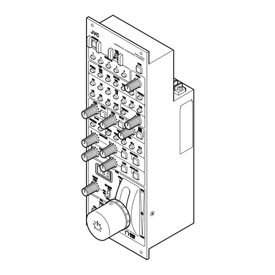
Names and Functions of Parts Control Panel O O P P E E R R A A T T E E L L O O C C K K P P A A R R T T O O F F F F F F U U L L L L S S C C E E N N E E F F I I L L E E PART PART... -
Page 8: Getting Started
Getting Started Names and Functions of Parts (continued) Control Panel (continued) O O P P E E R R A A T T E E L L O O C C K K P P A A R R T T O O F F F F F F U U L L L L S S C C E E N N E E F F I I L L E E PART... - Page 9 [LEVEL] level adjustment knob: For adjusting the gamma level. LEVEL GAMMA Decreases the reproducibility of dark areas. Note: ● The feature is not available on the camera if the light of the corresponding button is not lit. Control using this unit is disabled in this case.
- Page 10 Getting Started Names and Functions of Parts (continued) Control Panel (continued) O O P P E E R R A A T T E E L L O O C C K K P P A A R R T T O O F F F F F F U U L L L L S S C C E E N N E E F F I I L L E E PART...
- Page 11 [PRESET LEVEL] Preset Level setting knob For setting the center value of the 4-f/stops (approximately) range when the [IRIS MODE] switch is set to PRESET . ● Example Center Value C・ ・ ・ ・ 16・ ・ ・ ・ ・ 11・ ・ ・ ・ 8・ ・ ・ ・ 5.6・ ・ ・ ・ 4・ ・ ・ ・ 2.8・ ・ ・ ・ 1.4 (Close) 4-f/stops Variable Range...
- Page 12 Getting Started Names and Functions of Parts (continued) Control Panel (continued) O O P P E E R R A A T T E E L L O O C C K K P P A A R R T T O O F F F F F F U U L L L L S S C C E E N N E E F F I I L L E E PART...
-
Page 13: Rear/Side Of Remote Control Panel
[KNEE POINT] Knee Point setting knob: For adjusting the knee point setting manually when the auto knee button is turned OFF . KNEE POINT Decreases the knee point. Note: ● The feature is not available on the camera if the light of the corresponding button is not lit. -
Page 14: Operation
TALLY CALL PREVIEW UNDER CLOSE MASTER BLACK RM-LP25U REMOTE CONTROL PANEL Note: ● Turn the power off when connecting. Setup ● Connect according to the instruction manual of the ● Set the [LOCK] switch to OFF . ● Set the [OPERATE] button to OFF (light off). -
Page 15: Shutter Settings
Shutter Settings For specifying the shutter settings. Press any of the shutter speed buttons. ● The selected shutter speed button lights up in orange, and the speed button that was previously selected turns green. OFF FULL S S C C E E N N E E F F I I L L E E PART PART SHUTTER... -
Page 16: Gain Settings
Operation Gain Settings For specifying the gain settings. Press any of the gain value buttons. ● The selected gain value button lights up in orange, and the gain value button that was previously selected turns green. GAIN GAIN 0 0 d d B B 3 3 d d B B 6 6 d d B B 9 9 d d B B... -
Page 17: White Balance Adjustment
White Balance Adjustment For specifying the white balance settings. Setup: ● Set the [BARS] button to OFF . ● Place a white object near the center of the screen under the same lighting conditions as the target subject and zoom in to fill the screen with white. ●... -
Page 18: Black Balance Adjustment
Operation Black Balance Adjustment For specifying the black balance settings. Setup: ● Set the [BARS] button to OFF . Automatic Adjustment Press [AUTO BLACK] (push once). ● The [AUTO BLACK] indicator lights up in orange. ● Auto black balance adjustment is performed and the value stored in the camera. -
Page 19: Scene File
Scene File You can save various settings of this product according to the different shooting conditions as scene files. You can save up to five different scene files, and recall them simply by pressing the button. You can also identify the status of the scene files based on the indicator light of the button. -
Page 20: Loading A Scene File
Operation Scene File (continued) Loading a Scene File To call a preset scene file: O O P P E E R R A A T T E E L L O O C C K K B B A A R R S S [OPERATE] P P A A R R T T O O F F F F F F U U L L L L... -
Page 21: List Of Supported Features In Scene Files
Clearing is complete. ● The [OPERATE] button switches back to a solid orange light, and the light of the [SCENE FILE] button for which settings have been deleted is turned off. OPERATE LOCK PART OFF FULL SCENE FILE Not lit PART Memo: ●... -
Page 22: Adjustment Of Indicator's Brightness
Operation Adjustment of Indicator's Brightness The brightness of the indicator light on the control panel can be adjusted in five levels. Indicators for which brightness cannot be adjusted: ● [CALL] button ● [PREVIEW] button ● [TALLY] indicator Set the [LOCK] switch to OFF . OPERATE LOCK PART... -
Page 23: Tally Input Terminal
● 10 kK for internal, connected to 5 V power ● Input signals can be set using the DIP switch ( A 24 page DIP Switch 6 ) Tally Input Terminal RM-LP25U DC 5 V TALLY IN (PGM,PVM) Tally Input Equivalent... -
Page 24: Setting Selection Dip Switch
(ALC+EEI). To use GY-HD200 and GY- HD250 when only the gain value is automatically set (ALC), please consult your nearest JVC's authorized dealers. DIP Switch 2 For setting the [AUTO IRIS LEVEL] feature. -
Page 25: Operable Features
BLACK PAINT IRIS Iris Control Unit Iris F Value Display LEVEL MASTER BLACK TALLY CALL PREVIEW AUTO KNEE KNEE POINT BARS TALLY(PGM) TALLY(PVW) version of the camera's software. For details, please consult JVC's authorized dealers. GY-HD200 GY-HD201 : Enabled, : Disabled... -
Page 26: Operation Of Connected Camera
Operation Operation of Connected Camera When RM-LP25U is connected to a camera, all features that are available on RM-LP25U can only be controlled via RM- LP25U, and control of these features using the camera is disabled. Switches on the camera that are disabled, as well as disabled menu items are as follows. -
Page 27: Others
Others Troubleshooting Troubleshooting Check Point Power does not turn ON/OFF upon pressing the Operate button. Unable to select -3dB or - 6dB of the gain selection button when they are pressed. Function cannot be turned ON (orange light on) after pressing the white paint button. - Page 28 LST0594-001A © 2007 Victor Company of Japan, Limited...
Need help?
Do you have a question about the RM-LP25U and is the answer not in the manual?
Questions and answers