Table of Contents
Advertisement
Advertisement
Table of Contents

Related Manuals for Robe Image Spot 250 AT


Summary of Contents for Robe Image Spot 250 AT
-
Page 2: Table Of Contents
IMAGE SPOT 250 AT Table of contents 1. Introduction ........................3 1.1.Description of the device .................... 4 2.Safety ..........................6 2.1.Safety instructions ...................... 6 2.2.Operating determinations ................... 6 3.Installation ........................7 3.1.Fitting/Exchanging the lamp ..................7 3.2.Inserting/Exchanging rot. gobos .................. 9 3.3.Rigging ........................ -
Page 3: Introduction
BEFORE YOU INITIAL START - UP! 1. Introduction Thank you for having chosen a IMAGE SPOT 250 AT. You acquired a versatile, powerful and intelligent lighting- effect. Unpack your IMAGE SPOT 250 AT and make sure that there are no damages caused by transportation. Should there be any, please consult your local dealer and do not take the device into operation. -
Page 4: Description Of The Device
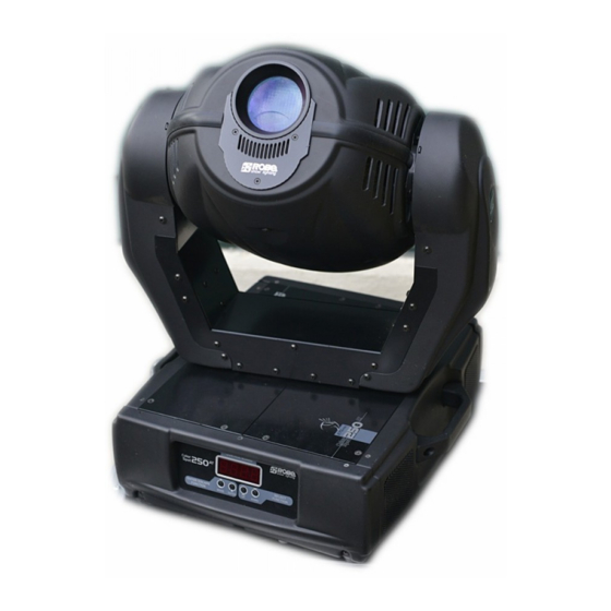
1.1.Description of the device 1 - Projector head 4 - Transport handle 2 - Yoke 5 - Control panel 3 - Rear panel 6 - Base Rear panel of the base 7 - DMX output 9 - Power cord 8 - DMX input 10 - Fuse holder 11 - Power switch Control panel... - Page 5 Infra-red remote control 21 - Red LED 22 - Up-button 23 - Down-button 24 - Infra-red transmitter 25 - Lamp on-button 26 - Mode-button 27 - Blackout/lamp off-button 28 - Enter-button...
-
Page 6: Safety
2.Safety 2.1.Safety instructions Caution ! Be careful with your operations.With a dangerous voltage you can suffer a dangerous electric shock when touching the wires This device has left our premises in absolutely perfect condition. In order to maintain this condition and to ensure a safe operation, it is absolutely necessary for the user to follow the safety instructions and warning notes written in this manual. -
Page 7: Installation
fixture at the transport handles. When choosing the installation-spot, please make sure that the device is not exposed to extreme heat, moisture or dust. There should not be any cables lying around. You endanger your own and the safety of others! The minimum distance between light-output and the illuminated surface must be more than 1,3 meter. -
Page 8: Lamp Adjustment
Fastening screws Fastening screws Top cover Lamp cover Lamp To insert the lamp MSD 250W/2 open the top cover of the projector-head (see the drawing to identify which cover is top) by loosening the 3 screws on the cover. Then open the small lamp cover by loosening 2 fastening screws (see the drawing). If changing the lamp, remove the old lamp from the socket. -
Page 9: Inserting/Exchanging Rot. Gobos
The lampholder is aligned at the factory. Due to differences between lamps, fine adjustment may improve light performance. Strike the lamp, cancel all effects, open the shutter and dimmer , focus the light on a flat surface (wall) or use function "LAAd"... -
Page 10: Rigging
3.3.Rigging DANGER TO LIFE! Please consider the respective national norms during the installation! The installation must only be carried out by an authorized dealer! The installation of the projector has to be built and constructed in a way that it can hold 10 times the weight for 1 hour without any harming deformation. - Page 11 The fixture can be placed directly on the stage floor or rigged in any orientation on a truss without altering its operation characteristics (see the drawing). There are two possibility how to fix the IMAGE SPOT 250 AT on a truss: with the clamp brackets or mounting plate (see the drawings below).Use the rigging clamps with screws M12.
- Page 12 Fixation via a mounting plate (mounting plate is not standard part of the fixture) The fixture's base enables to be mounted in two ways using the special mounting plate : 1. Screw the 2 clamps to the included mounting plate with M12 bolts and nuts through the holes in the mounting plate.
-
Page 13: Connection To The Mains
3.4.Connection to the mains Connect the fixture to the mains with the enclosed power-plug. The earth has to be connected! The occupation of the connection-cables is as follows: Cable (EU) Cable (US) International Brown Black Live Light blue White Neutral Yellow/Green Green Earth... -
Page 14: Dmx- 512 Connection, Master/Slave Connection
US-version power supply settings: 120V/60Hz 3.6.DMX- 512 connection, master/slave connection Controller operation Master/slave operation Only use a stereo shielded cable and 3-pin XLR-plugs and connectors in order to connect the controller with the fixture or one fixture with another. Occupation of the XLR-connection: DMX - output DMX-input XLR mounting-socket:... - Page 15 Building a master/slave-chain: Connect the DMX-output of the master fixture in the data-chain with the DMX-input of the first slave. Always connect output with the input of the next slave until all slaves are connected (up to 9 fixtures). Caution:It’s necessary to insert the XLR termination plug (with 120 Ohm) into the input of the master fixture and into the output of the last slave fixture in the data link in order to ensure proper transmission on the data link.
-
Page 16: Dmx Protocol
4.DMX Protocol Channel Channel Value Function Type of control 16 bit 8 bit 0-255 Pan movement by 530° proportional Pan fine 0-255 Fine control of pan movement proportional Tilt 0-255 Tilt movement by 280° proportional Tilt fine 0-255 Fine control of tilt movement proportional Speed of PAN/TILT movement Max. -
Page 17: Control
5.Control The IMAGE SPOT 250 AT is controled by the 4-buttons control panel on the front side of the base or by the 6- buttons infra-red remote controller. Control panel: Two LEDs on the control panel display the fixture status. Red LED indicates normal operation after switching the fixture on.Green LED indicates the lamp is switched on. -
Page 18: Dmx Addressing
IMAGE SPOT 250 AT will respond to the controller. If you set, for example, the address to channel 5, the IMAGE SPOT 250 AT will use the channel from 5 to 14 for control. - Page 19 "Stand-alone operation" can be applied to the single fixture (the fixture may be set to the master /slave mode or controller mode ) or to multiple fixtures operating synchronously. Synchronous operation of multiple fixtures requires that they must be connected on a data link and one of them is set as a master (master mode) and the rest as the slaves (slave mode).The slaves are assigned to SLA1-SLA9 and on the certain slave address can be connected only one fixture.To set the fixture as the master or slave , see the "Addressing"...
-
Page 20: Functions Of The Control Panel
The played program is the same for all time(light level) periods. From the master's control panel is possible to control any slave in a master/slave chain. Note:Disconect the fixtures from the DMX controller before master/slave operating ,otherwise data collisions can occur and the fixtures will not work properly! Note:It’s necessary to insert the XLR termination plug (with 120 Ohm) into the input of the master fixture and into the output of the last slave fixture in the data link in order to ensure proper transmission on the data link. -
Page 21: Slave Control
2. Press [Enter]-button and use the [Up] and [down] buttons to select "MA.SL."-menu. 3. Press[Enter]-button(display flashes) and select"MASt."(to set the fixture as the master in a chain of multiple fixtures) or "SLA.1"-"SLA.9" (to set the fixture to be the slave in a chain of multiple fixtures) and press [Enter] to confirm. - Page 22 SPOT 250 AT has been fabricated. Press [Enter] or [Mode] to return to the menu. - The number of the hours that the IMAGE SPOT 250 AT has been powered On since the counter was last reset.Press [Enter] or [Mode] to return to the menu.In order to reset this counter to 0, you have to hold the [Up] and [Down]-button and press the [Enter]-button.
-
Page 23: Personality Options
[Mode] to return to the menu. 8.4.Personality options These options allow you to modify IMAGE SPOT 250 AT operating behavior. Press [Up] and [Down] buttons to select the desired option and press [Enter] to set the value or to see next submenu. - Page 24 - Lamp On after switching the fixture On This function enables to turn the lamp on automatically after switching the fixture on. Use the [Up] and [Down] buttons to select "On" if you wish to turn the lamp on automatically after switching the fixture on or "Off"...
- Page 25 - Display intensity With this function you can adjust the display-intensity from 20% to 100% . Use the [Up] and [Down] buttons to select the level of the display- intensity and press [Enter] to confirm or [Mode] to cancel and return to the menu. - Display-reverse With this function, you can rotate the display by 180°.
- Page 26 The fans keep the adjusted low speed until the temperature exceeds max. inside temperature of the fixture, then the IMAGE SPOT 250 AT automatically switches from low to high the fan speed. Note:The modes "Auto" and "HIGH" don´t interact to the DMX value on the channel 6 (0-127)! - Default settings Press [Enter] to reset all fixture personalities (not the adjusting functions) to the default values.
-
Page 27: Switching On/Off The Lamp
This function allows you to run a special demo-test sequences without an external controller, which will show you some possibilities of using IMAGE SPOT 250 AT. Press [Up] and [Down] keys to select the "Mod1" or "Mod2" sequences. The "Mod1" is suitable for projections on the wall, ceiling or ground without any head-movement, the "Mod2"... - Page 28 -Presetting playback This function allows you to select the the program which will be played in the stand-alone mode after switching the fixture on( LAAu-function must be "On" in the menu LAPr) .The selected program will be also used for the operating with the time periods or the light level period( LAAu-function must be "OFF"...
- Page 29 -Timer 2 -start This function sets the start of the time period 2.Use the [Up] or [Down] buttons to specify the start hour and press the [Enter]-button.Use the [Up] or [Down] buttons to specify the start minute and press [Enter]. -Timer 2-stop This function sets the finish of the time period 2.Use the [Up] or [Down] buttons to specify the stop hour and press the [Enter]-button.Use the [Up] or [Down] buttons to specify the stop minute...
- Page 30 (playing is forced by the master). - Editing program This menu item allows you to select a program to edit or create.The IMAGE SPOT 250 AT has one built-in program ("tESt") and the 3 free programs,each up to 99 steps.
-
Page 31: Reset Function
The editting programs "PrG.1,PrG.2,PrG.3" are saved in the current modified fixture (master or slave1-9). 8.8.Reset function Press [Enter] button to run a reset. This option enables the IMAGE SPOT 250 AT to index all effects (functions) and return to their standard positions. - Page 32 -- Fixture code The option contains identification code (1-9999) for the fixture, which is used for the master/slave operation. - Adjusting the default positions of gobo wheels By this function you can calibrate and adjust the gobo wheels to their standard/right positions. Disconnect the controller.Use the [Up] and [Down] buttons to browse through the adjusting menu - the display shows step by step these messages: "PAn,FPAn, tilt,Ftilt,SPEd,Func,rGob, Grot, Foc, dimr, FCAL"...
-
Page 33: Error And Information Messages
9.Error and information messages This message appears if you try to switch on the lamp within 5 minutes after having switched it off (the lamp is too hot). The message will appear on the display if the lamp doesn't ignite within 28 seconds. The IMAGE SPOT 250 AT will store this information and automatically ignite the lamp when the 5 minutes period has expired. -
Page 34: Technical Specifications
10.Technical specifications Power supply EU-model: 208/230/240V AC, 50/60Hz ~ Fuse: T 3.15A @ 230V US-model: 100/120/208/230/240V AC, 50/60Hz ~ Fuse: T 6,3A @ 120V Power consumption: 430 VA Remote control: 2 batteries 1,5V, size AAA Lamp MSD 250/2 GY-9,5 Optical System - High luminous-efficiency parabolic mirror and double condenser system - All lenses are anti-reflection coated -15°... - Page 35 2 truss orientation Safety chain/cord attachment point Temperatures Maximum ambient temperature : 45° C Maximum housing temperature : 80° C Minimum distances: Min.distance from flammable surfaces: 0,5m Min.distance to lighted object: 1,3m Dimensions and weight Weight (net):20 kg Beam path Optional accessories Mounting plate..........99010500...
-
Page 36: Maintenance And Cleaning
11.Maintenance and cleaning The operator has to make sure that safety-relating and machine-technical installations are inspected by an expert after every four years in the course of an acceptance test. The operator has to make sure that safety-relating and machine-technical installations are inspected by a skilled person once a year. - Page 37 batteries bottom cover Should you need any spare parts, please use genuine parts. If the power supply cable of this device will be damaged (cable firmly connected with the device), it has to be replaced by authorized dealers only in order to avoid hazards. If the power supply cable of this device will be damaged (replaceable cable), it has to be replaced by a special power supply cable available at your dealer.
Need help?
Do you have a question about the Image Spot 250 AT and is the answer not in the manual?
Questions and answers