Table of Contents
Advertisement
Quick Links
Advertisement
Table of Contents

Related Manuals for LSC maXim


Summary of Contents for LSC maXim
- Page 1 LIGHTING CONTROL DESK OPERATOR MANUAL DEC 2001 Software Version 0.85 L.S.C. Lighting Systems (Aust) Pty Ltd A.B.N. 090 801 675 7 University Place, Clayton, Victoria, 3168 Australia Tel: +61 3 9561 5255 Fax: +61 3 9561 5277 Email: info@lsclighting.com.au Web site: www.lsclighting.com.au...
-
Page 5: Record A Scene
[F/A] (chase number) (any of the red bank or blue bank flash/assign buttons) (or the grab F/A button on S & M models only). Each step of a chase consists of a either a previously recorded scene or a snapshot of the maXim output. •... - Page 6 [F/A] (stack number) (any of the red bank or blue bank flash/assign buttons) (or the grab F/A button on S & M models only). Each step of a stack consists of a either a previously recorded scene, chase or a snapshot of the maXim output. To add a scene or chase as a step press [page] (optional) [F/A] (scene or chase number) (any of the red bank or blue bank flash/assign buttons)..
-
Page 7: Table Of Contents
9.6 REMOVING (DELETING) A CHASE ____ 37 1.4 OPTIONS __________________________ 3 10.0 GRAB MASTER (S & M Models) __ 38 1.5 CARING FOR YOUR maXim ___________ 3 10.1 OVERVIEW ______________________ 38 1.6 LABELING YOUR maXim _____________ 4 10.2 GRAB AS A GRAB MASTER_________ 38 1.7 BUTTONSTROKE TERMINOLOGY _____ 4... -
Page 8: Introduction
Operator Manual Introduction 1.0 INTRODUCTION The maXim is a powerful yet easy to use lighting control desk that is suited to a wide range of applications. It is available in 5 models. 1.1 MODEL RANGE This manual covers all 5 models of the maXim. -
Page 9: Specifications
Custom flightcases for all models are available to house the maXim, 12V gooseneck lamps, manual, power lead and floppy disks. 1.5 CARING FOR YOUR MAXIM The maXim is manufactured from quality components and will give many years of service if you take some basic precautions. LSC Lighting Systems (Aust) Pty. Ltd. -
Page 10: Labeling Your Maxim
If any doubt exists, obtain the assistance of qualified personnel. • If your maXim is to be used "on the road", you should use it (optional) flight case to protect the desk. Transport the maXim with all faders in the fully down position. This gives the faders maximum protection from damage. -
Page 11: Getting Connected
2.2 DIGITAL OUTPUTS (DMX 512/1990) The maXim S and M models have a single DMX 512 connector and the L, XL and XXL have two DMX 512 connectors, one for “Universe 1 DMX channels” and the second for “Universe 2 DMX channels”. -
Page 12: Front Panel Layout
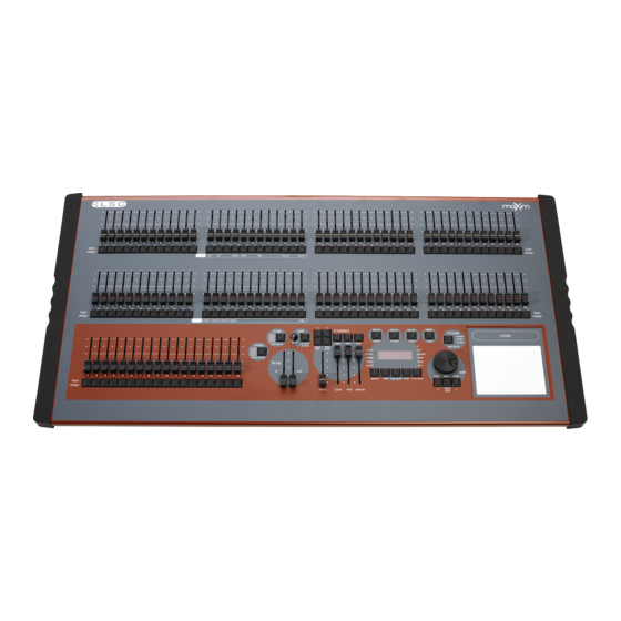
Operator Manual Layout 3.0 FRONT PANEL LAYOUT There are 5 maXim models (S, M, L, XL, XXL) with 2 similar panel layouts, S & M and L, XL & XXL. maXim M maXim L LSC Lighting Systems (Aust) Pty. Ltd. -
Page 13: Faders And Masters
Operator Manual Layout The front panel of the maXim can be divided into two areas; • Faders and mastering. • Recording and editing. Many of the buttons listed below perform more than one function. The current function depends upon what the operator is doing at the time. Each of these different functions is described under the relevant button below. - Page 14 The brightness of its LED indicator shows the level of the Grab master at the output of the maXim. It also will flash slowly whilst a timed fade is in progress.
- Page 15 • In SOLO mode, when a FLASH/ASSIGN button is pressed, the channels that are being flashed will come on (at the level of the FLASH level master), and the normal output of the maXim will be blacked out, leaving only the channels that are being flashed on stage.
-
Page 16: Recording And Editing
Comprehensive information (including these messages) are also shown on the video output. Record Scene Button Used to select RECORD SCENE mode or to record a snapshot of the output of the maXim as a step in a stack or a chase or into the Grab master. - Page 17 • Runs a chase in the FORWARD direction. • Steps a stack forward when editing. • Increments through the DMX address numbers when patching. • Answers “YES” to a request from the maXim. < (No) button • Runs a chase in the REVERSE direction.
-
Page 18: Modes Of Operation
• The Blue bank has dedicated Playbacks and control the levels of Scenes or Chases. You may freely change red modes at any time during your operation of the maXim and the current red mode is always shown by the “LED” MODE indicators beside the mode red bank button. -
Page 19: Wide Mode
Yellow master and of course, you may use the In and OUT time faders to set the fade times. ADVANTAGE You have access to all of the channels that are available on the maXim. This is most useful when you are RECORDING scenes as you can utilise all channels to create your scenes. (See “Scene Mode”... - Page 20 You may also use the Red Playbacks to play chases that you have recorded. The maXim L, XL and XXL models all have dedicated blue playbacks that are always available, irrespective of the mode of the red bank.
-
Page 21: Quickstart Tutorial
CREATING A “LOOK” ON STAGE Place every fader on the maXim to its lower limit. Now fade up the Yellow master to maximum (top). Fade up channel 1 on the Yellow fader bank. The fixture(s) connected to dimmer output 1 fades up on stage. -
Page 22: Recording A Scene
All of the “looks” that you have created have been made on a “one off” basis. That is, they have not been recorded into the memory of the maXim. If you needed to re-use a look that you had previously created, then you need to take a note all of the channels and their respective levels together with the fade times (if any), and then manually setup the faders for the look and fade times. -
Page 23: Replaying A Scene
These scenes are now available on Red Playbacks 1 and 2 respectively because Page 1 is shown as the current red page. Fade up the Red master, then to reveal scene R1.01 on stage, fade up red Playback 1(Red fader 1). LSC Lighting Systems (Aust) Pty. Ltd. Page 17 of 66... -
Page 24: Recording A Chase
For descriptions of these operations, see the “SCENES” and “GRABMASTER” chapters. 5.5 RECORDING A CHASE Each step of a chase consists of either a previously recorded scene or a snapshot of the maXim output. For simplicity, record a 6 step chase consisting only of snapshots. Make step 1 channel 1, step 2 channel 2, etc. -
Page 25: Recording A Stack
5.7 RECORDING A STACK A Stack is a list of steps consisting of scenes or chases or snapshots (of the maXim output) that are arranged in the order that they are to be replayed. A Stack is designed to be played one step at a time with the transitions being a timed DIPLESS CROSSFADE executed by pressing the stack masters >... -
Page 26: Memory Structure
1 2 3 4 5 6 7 8 9 10 11 1 2 GRAB Scenes Stacks or MASTER Chases EDIT STACK MASTER ASSIGN COPY Basic Memory structure of a maXim S. LSC Lighting Systems (Aust) Pty. Ltd. Page 20 of 66... - Page 27 Blue PAGE 2 1 2 3 4 5 6 Blue Page Key Blue PAGE 1 1 2 3 4 5 6 Scenes Stacks or Chases Basic Memory structure of a maXim L. LSC Lighting Systems (Aust) Pty. Ltd. Page 21 of 66...
-
Page 28: Mode/Page Freeze
Operator Manual Memory Structure The storage capacity of your maXim is noted in the specification table in the “Introduction” chapter. The maXim is continually checking its memory and compacting it to give you the maximum storage capacity. A Memory Expansion Module is available as an option. You can check the current memory usage via the diagnostics. -
Page 29: Fade Times & Channels
“Select” allows you to change the RUN TIME conditions (in time and out time) on the selected Playback. When you have finished adjusting the time, and you exit “Select” (press [select] again) the maXim asks “Save Changes To Memory?” If you answer “no”, the original LSC Lighting Systems (Aust) Pty. Ltd. -
Page 30: Stack Fade Times
Edit wheel. LSC Lighting Systems (Aust) Pty. Ltd. Page 24 of 66... -
Page 31: Scenes
Individual IN, and OUT fade times may be recorded for every scene. 8.2 SCENE RECORDING The maXim provides a variable method of recording scenes. The fastest method takes just 2 buttonstrokes and uses the default parameters that may be set by the user. The longest method lets you select a different page in memory and also record separate IN and OUT fade times. - Page 32 (only 1 channel on at low level) in a spare scene number. (The maXim will not record a scene if there are no channels on the output.) When a blind recording is needed, copy your special scene to the bank/page/scene number where it is required then edit that scene and set the single channel to 0 and turn on the required channels.
-
Page 33: Scene Playback
EDIT wheel. When a time is set lower than 0 seconds, it is controlled by the “out time” manual fader. When you have finished adjusting the time press; [Select] LSC Lighting Systems (Aust) Pty. Ltd. Page 27 of 66... -
Page 34: Editing A Scene
Operator Manual Scenes the maXim asks “Save Changes To Memory?” If you answer “no”, the original memory is not affected, but the changes that you have made are retained in the Playback until such time as the scene is replaced on that Playback (by changing pages or mode). If you answer “yes”, the changes are also copied to memory. -
Page 35: Copying A Scene
8.6 REMOVING (DELETING) A SCENE To remove (delete) a scene from memory press [remove] LSC Lighting Systems (Aust) Pty. Ltd. Page 29 of 66... - Page 36 If required, repeatedly press [red page] or [blue page] until the required page number is displayed, then press [F/A] (Scene number) of the scene to be removed. The display asks you to confirm your action. Press [yes]. LSC Lighting Systems (Aust) Pty. Ltd. Page 30 of 66...
-
Page 37: Chases
(which is taken when that step is added to the chase). Up to 250 steps may be recorded for each chase and up to 810 separate chases may be recorded into the memory, depending upon your maXim model. See the specifications table in the “Introduction” chapter for details. - Page 38 Operator Manual Chases [F/A] (scene number). • To record a snapshot (of the current maXim output) as a step, press; [record scene]. Continue to record steps as above. When all steps have been recorded, complete the stack by pressing [record chase].
-
Page 39: Chase Playback
Chases CHASE CROSSFADE Traditionally, chases will snap (instantly switch) from step to step but in the maXim you may also elect to record a crossfade value for the chase so that it will crossfade from step to step. The Crossfade is recorded as a percentage of the chase rate. - Page 40 Playback. When you have finished controlling the chase, and you exit “Select” (press [select] again) the maXim asks “Save Changes To Memory?” If you answer “no”, the original memory is not affected, but the changes that you have made are retained in the Playback until such time as the Chase is replaced on that Playback (by changing pages or mode).
- Page 41 CROSSFADE Traditionally, chases will snap (instantly switch) from step to step but in the maXim you may also elect to record a CROSSFADE time for the chase so that the chase will crossfade from step to step.
-
Page 42: Editing A Chase
To remove the step, press [remove], [yes]. If necessary, press [>] or [<] to start the chase again in the desired direction then press [edit] to end the editing function. All changes are automatically saved. LSC Lighting Systems (Aust) Pty. Ltd. Page 36 of 66... -
Page 43: Copying A Chase
If required, repeatedly press [red page] or [blue page] until the required page number is displayed, then press [F/A] (chase number) of the chase to be removed. The display asks you to confirm your action. Press [yes]. LSC Lighting Systems (Aust) Pty. Ltd. Page 37 of 66... -
Page 44: Grab Master (S & M Models)
10.2 GRAB AS A GRAB MASTER The Grab master allows you to “GRAB” and maintain the current output of the maXim by taking a “snapshot” of the output and holding it the Grab master, thus freeing the rest of the maXim for other operations. -
Page 45: Grab As A Chase Master
[F/A] (memory number). The display confirm the copy. A stack in the grab master can be also copied to the stack master. Press: [assign/copy] [F/A] (grab) [stack flash] LSC Lighting Systems (Aust) Pty. Ltd. Page 39 of 66... -
Page 46: Stacks
Up to 500 steps may be recorded in each stack and between 108 and 810 separate stacks may be recorded into the memory depending upon the model or your maXim. See the specifications table in the “Introduction” chapter for details. - Page 47 “Fader” (IN or OUT time Fader) control. If you do not enter a time then the default settings will be used. The default times are; • SCENE The in and out fade times from that scene LSC Lighting Systems (Aust) Pty. Ltd. Page 41 of 66...
-
Page 48: Stack Playback
When the stack reaches the end, it will wrap around to the start. INITIATING A CROSSFADE To crossfade from the current step to the next step, press [ >] (forward). LSC Lighting Systems (Aust) Pty. Ltd. Page 42 of 66... - Page 49 Hint: If you need a link time in every step of a stack (to make it chase) set the default link time using the preference function. See the “UTILITIES” chapter for details. LSC Lighting Systems (Aust) Pty. Ltd. Page 43 of 66...
-
Page 50: Editing A Stack
To select a scene as the added step press [page] (optional) [F/A] (scene number). • To record a snapshot (of the current maXim output) as the added step press [record scene]. • To select a chase as the added step press [page] (optional) [F/A] (chase number). - Page 51 Any changes that you have made will automatically be saved in memory. EDITING A STACK NAME Names are edited in the same way as they are recorded, not from edit mode. See “NAMING A STACK” above for details. LSC Lighting Systems (Aust) Pty. Ltd. Page 45 of 66...
-
Page 52: Copying A Stack
The display asks you to confirm your action. Press [yes]. 11.7 CLEARING THE STACK MASTER To remove (clear) a stack from the stack master, press; [remove] [stack flash]. The display asks you to confirm your action. Press [yes]. LSC Lighting Systems (Aust) Pty. Ltd. Page 46 of 66... -
Page 53: Flash
If the FLASH level is set to minimum, then no channels will come on when a FLASH button is pressed. If the maXim is in ADD mode, and a channel is already ON when it is flashed, the flash level acts together with any existing level for that channel on a Highest Takes Precedence basis. -
Page 54: Patch
The screen confirms your action. If the maXim has had a “total reset” or if all patches have been “removed”, no patches will exist and there will be no output from the maXim. You will need to “Edit the Patch” (below). - Page 55 DMX addresses patched to that channel. 1 TO 1 PATCH A 1 to 1 patch is available to speed the patching process. It directly connects each maXim channel number to its matching DMX number. To add a “1 to 1 patch”, Hold [function], tap [patch].
-
Page 56: Patpad
Operator Manual Pat Pad 14.0 PATPAD This feature is yet to be implemented. LSC Lighting Systems (Aust) Pty. Ltd. Page 50 of 66... -
Page 57: Sound To Light (Stl)
Operator Manual 15.0 SOUND TO LIGHT (STL) This feature is yet to be implemented. LSC Lighting Systems (Aust) Pty. Ltd. Page 51 of 66... -
Page 58: Utilities
16.0 UTILITIES 16.1 DISK OPERATIONS The maXim is fitted with a 3.5 inch double sided, high density, (1.44 MB), disk drive (optional on S & M models). This is the same type of disk used with IBM compatible computers. When you save or load a show from disk, you copy the entire contents of the maXim's memory. -
Page 59: Setup
The display asks “RESET will clear all memories - Continue?”. Press [yes]. POWER ON RESET If the maXim is not responding to your actions you will not be able to perform a reset as described above. In this case, switch off the maXim and wait for 10 seconds then;... -
Page 60: Video
16.4 VIDEO VIDEO MONITOR Your maXim is fitted with a VIDEO output connector (optional on S & M models). Simply plug a SVGA monitor into the VIDEO connector and connect the monitor to mains power. The maXim provides all the necessary video and synchronisation signals for the SVGA monitor. -
Page 61: Diagnostics
The bargraphs are laid out in a similar fashion to the maXim faders. Their intensity levels are shown in tens on the side axis of the display and in units inside each individual bar. The “Fixture Intensity”... -
Page 62: Software Updates
[no]. 16.6 SOFTWARE UPDATES The maXim operating system (firmware) can be upgraded using the mLINK kit which consists of a connection cable and installation software. If you do not have an mLINK kit either contact LSC or one of their distributors or you can also make your own cable (see below) and you can download the installation software from the LSC website. - Page 63 (PC) comm port to the maXim (DMX512 Universe1 connector). On power up, the maXim sends a request out of its DMX outlet asking if an mLINK program is listening. If mLINK is not there, the maXim continues on and ignores any further communications.
- Page 64 It defaults to COM1. If your computer has a mouse, modem or some other device connected to COM1, you will need to COM2. The commands above use COM1 as the default.
- Page 65 2 U filename /v - For COM 2 Ensure the cable is connected between the PC and the maXim and then power up the maXim. You should now be able to see messages being sent and received by the PC Other mLINK option can be seen by typing “mLINK”...
-
Page 66: Rear Panel
Rear panel layout of a maXim L. The rear panel of a maXim L is shown. The smaller maxims do not have the second desk lamp (8) or DMX512 Universe 2 (9) connectors and the video and disk drive are optional. -
Page 67: Appendix A: Dmx 512
MaXim S In this setup, the DMX output signal from the maXim is fed to the DMX input of the first dimmer rack. As the first dimmer in this rack is to be controlled by DMX channel 1, the address switch is set to channel 1. - Page 68 As the DEMUX box is set to DMX address 25, the 12 analogue dimmers would be controlled by channels 25 through 36. The end of each DMX line must be terminated. LSC Lighting Systems (Aust) Pty. Ltd. Page 62 of 66...
-
Page 69: Appendix B: Terminology
A lighting “LOOK” is the collection of channels at their various levels (intensities) that are contributing to the output of the maXim at any one time. A “look” may be made up of a collection of channels or a single scene (see below) or a combination of several scenes. It may even be a single channel. - Page 70 If more than 512 DMX channels are required, then more DMX outputs are used. The numbers on each DMX output are always 1 to 512. To differentiate between each DMX output they are called Universe1, Universe 2 etc.. LSC Lighting Systems (Aust) Pty. Ltd. Page 64 of 66...
-
Page 71: Index
TYPICAL APPLICATIONS........60 BLIND SCENE RECORDING ........26 UNIVERSE 2 ............59 BUMP .............. See flash UNIVERSES ............60 —C— —E— CARING FOR YOUR maXim ........3 EDIT WHEEL.............. 11 CHANNELS DEFINITION............62 —F— LEVEL DISPLAY..........28, 53 LEVEL INDICATORS..........8... - Page 72 NAME..............29 RECORDING ............ 16, 25 WIDE MODE .............. 13 BLIND..............26 FADE TIMES............. 26 NAME..............26 —Y— REPLAYING ............. 17, 27 CONTROLLING LEVEL ........27 YES KEY ..............11 LSC Lighting Systems (Aust) Pty. Ltd. Page 66 of 66...
Need help?
Do you have a question about the maXim and is the answer not in the manual?
Questions and answers