Table of Contents
Advertisement
Advertisement
Table of Contents
Troubleshooting

Related Manuals for AEG Protect A. 1000


Summary of Contents for AEG Protect A. 1000
- Page 1 UPS OPERATING INSTRUCTIONS PROTECT A. PROTECT A. 1000 PROTECT A. 1400...
- Page 3 Thank you for deciding to purchase the PROTECT A. UPS from AEG Power Solutions. The following safety instructions are an important part of the operating instructions are will protect you against problems from operating errors and possible dangers. Please read...
-
Page 4: Notes On These Operating Instructions
Uninterruptible Power Supply (UPS), PROTECT A. 1000 or PROTECT A. 1400 - referred to as PROTECT A. in this document - safely and properly, and for its intended purpose. These operating instructions contain important information for avoiding dangers. Please read these instructions carefully prior to... - Page 5 AEG or its representatives without prior notice in the event of maintenance and repair work being carried out with anything other than original AEG parts or spare parts purchased from AEG.
-
Page 6: Table Of Contents
Table of Contents Notes on these Operating Instructions......4 System Overview ..............7 Brief Overview............7 Principle of Operation..........8 Safety ................10 General Safety Instructions........10 Safety Instructions for PROTECT A......10 CE Certificate ............14 Technical Data ............15 Set-up ................17 Unpacking and Inspection........17 Installation Site............18 Connections, Operating and Display Elements ..19 Installation and Operation ..........20 Test ................20 Installation ..............20... -
Page 7: System Overview
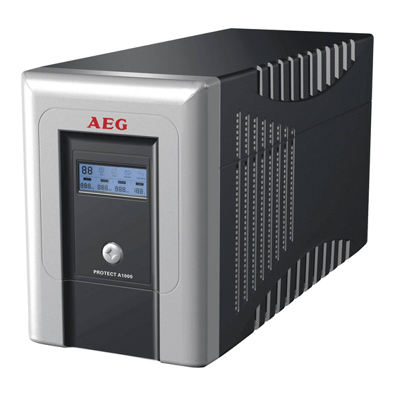
The PROTECT A. series is a compact, interactively operating UPS available with nominal power output ratings 500, 700, 1000 and 1400 VA. This document describes both types, PROTECT A. 1000 and PROTECT A. 1400. Brief Overview The LED display and a pushbutton switch are located on the front of the UPS for straightforward monitoring and operation. -
Page 8: Principle Of Operation
Important UPS data is monitored permanently and transferred to the computer via USB or the RS232 interface and using the CompuWatch software. Features of the PROTECT A.: ♦ VI (line – interactive) protection technology ♦ Automatic voltage regulation against mains voltage deviations (AVR) ♦... - Page 9 the internal energy storage, something which in turn has a positive effect on battery availability. Line Mains A. V. R. filter Load Rectifier Inverter Battery UPS Block diagram PROTECT A. The static bypass switch is activated in the event of a mains failure.
-
Page 10: Safety
Safety General Safety Instructions Read these operating instructions carefully prior commissioning of the PROTECT A. UPS and observe the safety instructions! Only use the unit if it is in a technically perfect condition and always in accordance with its intended purpose, while being aware of safety and danger aspects, and in accordance with the operating instructions! Immediately eliminate any faults that could be detrimental to safety. - Page 11 The output may be live, even if the UPS is not connected to the mains supply, as the UPS has its own internal power supply (battery)! For health and safety reasons, the unit must be earthed correctly! PROTECT A. may only be operated with or connected to a 220 / 230 / 240 VAC mains with protective grounding using a mains connection cable with PE conductor (included in the delivery) that has been tested in accordance with German...
- Page 12 ♦ Condensation may occur if the UPS is brought from a cold environment into the room where it is to be installed. The UPS must be absolutely dry prior to start- up. As a result, leave it to acclimatise for at least two hours.
- Page 13 When replacing the batteries, the following must be observed: Only ever use identical, maintenance-free sealed lead batteries with the same data as the original batteries. Danger! Explosive! Never throw batteries into open fire. Never open or damage batteries. (Electrolyte may leak out and damage skin and eyes.
-
Page 14: Ce Certificate
CE Certificate... -
Page 15: Technical Data
Frequency in battery operation 50 Hz / 60 Hz ±1 Hz Nominal output current 4.3 A ( PROTECT A. 1000 ) 6.1 A ( PROTECT A. 1400 ) Changeover time in the event of a mains failure 2-6 ms (typical) - Page 16 Housing colour Silver/black Dimensions W x H x D [mm] 145 x 205 x 405 Weight [kg] 9.5 kg (PROTECT A. 1000) 10 kg (PROTECT A. 1400) Cooling type Increased natural air cooling Storage temperature range -15° C to +50° C...
-
Page 17: Set-Up
Check the shipping container for damage on arrival. If necessary, ask the transport company to check the goods and make a record of the damage in the presence of the transport company employee and report the damage to the AEG representative or dealer within eight days of delivery. -
Page 18: Installation Site
Check the content is complete: ♦ PROTECT A. with 1000 or 1400 VA ♦ Mains connection cable with shockproof plug acc. to CEE 7/7 Second mains connection cable with UK plug acc. to BS 1363 ♦ Two device connecting cables ♦... -
Page 19: Connections, Operating And Display Elements
Connections, Operating and Display Elements Front 1 Main switch of the UPS (mains switch) 2 LC display with: - Display of operating mode with pictograms - Measured value displays [V] - UPS capacity utilisation display [%] - UPS remaining op. time display [min.] - Fault indication Rear 1 Load connections with... -
Page 20: Installation And Operation
Installation and Operation Check Remove the UPS from its transport packaging and check that it has not been damaged in transit. If you find any damage, pack the unit up again and send it back to where you purchased it. Installation Install the UPS unit in a protected location where there is an adequate air supply and where it will be largely free from dust... -
Page 21: Charging
Charging The PROTECT A. is supplied with its battery fully charged. Nevertheless, energy may have been lost during transport, so the battery should be fully recharged before it is used for the first time. Connect the input of the UPS (no. 2 in the figure in chapter 4.3 on page 19) to the mains connection cable provided and plug the mains connector into a suitable shockproof socket. -
Page 22: Rj11 And Rj45 Data Line Protection (Modem / Phone / Fax / Network)
In this connection, note the special property of the two additional output sockets identified with “SURGE ONLY” (chapter 4.3 / no. 7 / pg. 19). These are always live irrespective of the other outputs. They are not backed up by the UPS, nor can they be switched off using the main switch of the UPS. -
Page 23: Operation
The interfaces are mutually exclusive. There is no provision for simultaneous operation of RS232 and USB. Operation Once you have connected the UPS to a suitable mains connection, you can start operation using the UPS main switch. Switching ON and OFF: To switch on, press the main switch on the front of the UPS (chapter 4.3 / no. -
Page 24: Battery Operation / Autonomous Operation
The connected loads are powered using the monitored and filtered mains voltage, which is additionally stabilised by the integrated A.V.R. control unit. The “LINE MODE” symbol shows that the unit is active. 5.7.2 Battery Operation / Autonomous Operation When there is a mains failure or if the input voltage moves outside the tolerance range, the inverter automatically switches over to autonomous mode and supplies the loads with voltage from the batteries. -
Page 25: System Diagnosis / Fault Test
5.7.4 Shutdown and UPS Management Software The “CompuWatch” software specially developed for these purposes by AEG continuously checks the mains supply and the UPS status. In conjunction with the “intelligent” UPS, this guarantees the... -
Page 26: Displays And Troubleshooting
Displays and Troubleshooting LC Display The blue backlit display is automatically activated after the mains voltage is connected. It operates irrespective of the main switch setting and also when a fault is indicated. 1) The start of operational readiness is signalled on the LC display by all the information content lighting up for about 3 seconds. - Page 27 4) If the UPS is in battery mode, the “BATTERY” pictogram lights up and the battery symbol flashes every second. The remaining standby time is displayed during battery operation according to the load applied. This time is shown in minutes and is indicated by the “MIN” pictogram. The display shows “0”...
- Page 28 Fault Possible fault cause CODE Output short circuit (output voltage less than 60 V) Overload indicator Immediate fault message in mains/normal operation with a capacity utilisation of > 120%, at a capacity utilisation > 110% the fault message comes after 5 minutes or after 30 seconds in battery operation.
-
Page 29: Warning Sounds
Warning Sounds Warning Meaning sound Sounds every 10 UPS is operating in battery mode. seconds. Sounds every UPS is running in battery mode and will shortly second. shut down (battery system has reached the battery undervoltage limit). Sounds every two Battery system faulty, it may have to be renewed seconds (battery diagnosis negative). - Page 30 Mains normal, but Miniature circuit breaker Press reset button of miniature “Battery” LED flashes triggered circuit breaker; Mains cable loose Insert the plug firmly into the non-heating appliance socket of the UPS. Communication Software is not installed Check the software settings. between UPS and correctly Support is available at...
-
Page 31: Maintenance
Maintenance The PROTECT A. consists of state-of-the-art, non-wearing components. We do, however, recommend regular visual checks of the unit to maintain its continuous availability and operational reliability. Check whether: ♦ there is any mechanical damage or foreign bodies can be found in the system, ♦... -
Page 32: Battery Replacement
Battery Replacement ATTENTION: A battery can cause an electric shock, and represents a considerable hazard if handled incorrectly. The following precautions should be taken before the battery is renewed. ♦ Switch off the UPS and disconnect the mains cable from the socket. ♦... - Page 33 Once you have lifted off the actual front panel (which you can put down on top of the unit as shown – never disconnect the flat-ribbon cable) next remove the internal battery cover. Now slowly pull the two battery blocks out forwards until you can access the cable plug connections.
-
Page 34: Storage And Disposal
Storage and Disposal Storage Long storage times without charging discharging the battery at regular intervals may lead to permanent damage of the battery. If the battery is stored at room temperature (20° C to 30° C) it will automatically discharge at a rate of 3-6% per month due to internal reactions. -
Page 35: List Of Terms
List of Terms Technical Terminology Automatic Voltage Regulation Automatic voltage regulation against mains voltage deviations DC/DC booster Circuit technology for increasing a DC voltage to a higher voltage level Emergency Power Off Device for emergency shutdown Power Factor Correction Circuit technology for minimising system disturbances (particularly important when connecting non-linear loads) Appliance protection... - Page 36 Guarantee Certificate Type: …….……………….…............Unit number:…….……………….…............ Date of purchase:…….……………….…..........Dealer stamp / signature Errors and changes excepted. AEG Power Solutions GmbH Emil-Siepmann-Straße 32 59581 Warstein-Belecke Germany Operating instructions BAL 8000024071 EN...
Need help?
Do you have a question about the Protect A. 1000 and is the answer not in the manual?
Questions and answers