
Related Manuals for Daewoo DWF-7560 series


Summary of Contents for Daewoo DWF-7560 series
-
Page 1: Service Manual
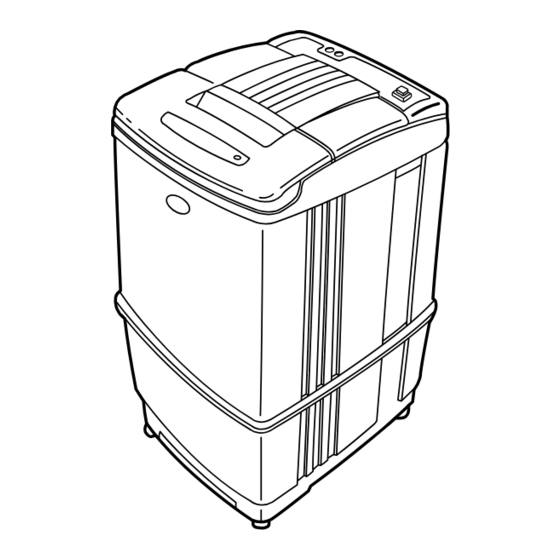
Service Manual Full-Auto Electric Washing Machine DWF-7560/7590 series DWF-8060/8090 series DAEWOO ELECTRONICS CO., LTD. -
Page 2: Table Of Contents
TABLE OF CONTENTS 1. SPECIFICATIONS..................................2 2. FEATURE AND TECHNICAL EXPLANATION ........................3 CONTROL SYSTEM FOR AUTO COURSE ..........................3 CONTROL SYSTEM FOR WOOL WASH ..........................3 CONTROL SYSTEM FOR WOOL SPIN ............................4 WATER FLOW TO ADJUST THE UNBALANCED LOAD......................4 FUNCTION FOR SOAK WASH..............................4 AUTOMATIC WATER SUPPLY SYSTEM ON BLANKET WASH ....................5 WATER FLOW ON STRONG WASH............................5... -
Page 3: Specifications
1. SPECIFICATIONS ITEM SPECIFICATIONS POWER SOURCE Available in All Local AC Voltage and Frequency POWER DWF-7560/90 370W (50Hz), 460W (60Hz) CONSUMPTION DWF-8060/90 400W (50Hz), 480W (60Hz) MACHINE DWF-7560/90 NON PUMP: NET; 48kg, GROSS; 52kg PUMP: NET; 49kg, GROSS; 53kg WEIGHT DWF-8060/90 NON PUMP: NET;... -
Page 4: Feature And Technical Explanation
2. FEATURE AND TECHNICAL EXPLANATION CONTROL SYSTEM FOR AUTO COURSE FUNCTION PRINCIPLE OF SENSING 1) Sensing the wave width of two ports of capacitor. 2) Choosing the 'A~D' course according to the wave width. 3) Setting up the most suitable time to wash, rinse and spin by the judgement. SENSING TIME Sense the wave width for 28 seconds from start of washing. -
Page 5: Control System For Wool Spin
CONTROL SYSTEM FOR WOOL SPIN It is a function to prevent the deformation of WOOL. PROGRESS CHART ON WOOL SPIN NORMAL WOOL R.P.M. ON-OFF WOOL TIME MOTOR NORMAL (sec) BALANCE SPIN NORMAL SPIN WATER FLOW TO ADJUST THE UNBALANCED LOAD It is a function to prevent eccentricity of the clothes after wash by rotating pulsator C.W and C.C.W for 20 seconds. -
Page 6: Automatic Water Supply System On Blanket Wash
AUTOMATIC WATER SUPPLY SYSTEM ON BLANKET WASH The water level would be lowered because the blanket absorbs water at the beginning of washing. Therefore, after 30 seconds, the operation is interrupted to check the water level, and then the water is supplied again until it is reached at the selected level. -
Page 7: Automatic Draining Time Adjustment
AUTOMATIC DRAINING TIME ADJUSTMENT This system set a drain time automatically depending on condition of draining. Good draining The washer begins spin process after drainage. Draining Bad draining Draining time is prolonged. condition No draining Program is stopped and gives the alarm. FUNCTIONAL PRINCIPLE 1. -
Page 8: Softener Dispenser
SOFTENER DISPENSER This is the device to dispense the softener automatically by centrifugal force. This is installed inside the auto-balancer. FUNCTIONAL PRINCIPLE 1. Softener stays in room (A) when pour the softener to softener inlet. 2. Softener move (A) to (B) by centrifugal force during intermediate spin process. 3. -
Page 9: Automatic Unbalance Adjustment
AUTOMATIC UNBALANCE ADJUSTMENT This system is to prevent abnormal vibration during intermittent spin and spin process. FUNCTIONAL PRINCIPLE 1. When the lid is closed, the safety switch contact is "ON" position. Contact of safety switch Lid closing 2. In case that wash loads get uneven during spin, the outer tub hits the safety switch due to the serious vibration, and the spin process is interrupted. -
Page 10: Automatic Power Off
AUTOMATIC POWER OFF P.C.B. ASS'Y sends a signal to the solenoid in the power switch 10 minutes later after complete washing. Then the solenoid pull the locking lever which had lock the push button. Therefore the power is turned off automatically. RESIDUAL TIME DISPLAY When the START/HOLD button is pressed, the residual time (min.) is displayed on the time indicator, and it will be counted down according to the process. -
Page 11: Gear Mechanism Ass'y
GEAR MECHANISM ASS'Y The proper water currents is made by the rotation of pulsator at a low speed (about 145 r.p.m) to prevent the damage to the small sized clothes. Pusator Shaft Spinner Shaft Roller Clutch Bearing Sun gear Planetary Planetary gear Internal gear Gear... -
Page 12: Functional Principle Of Bubble Washing Machine
PRINCIPLE OF INTAKE & OUTLET OF THE AIR INTAKE : ARMATURE moves to the upper side, and BELLOWS inhales the air. At same time, PROTECTOR B is open and A is close. OUTLET: ARMATURE moves to the down side, and BELLOWS exhaust the air. At same time, PROTECTOR B is close and A is open. -
Page 13: Structure Of Washing Machine
3. STRUCTURE OF THE WASHING MACHINE STRUCTURE OF WASHING MACHINE ACCESSORIES • COLD WATER INLET Hose Clamp Water Tap Adapter (COLD) After using the machine, Water Tap Adapter (HOT) close the water faucet [option] and turn off the power. • HOT WATER INLET [Option] In case of screw-shaped inlet hoses water tap adapters will be provided. -
Page 14: Function Of Control Panel
3 one of the other buttons. times pressing. seconds and then AUTO OFF turn it On again. DAEWOO AUTOMATIC TIME COURSE TEMP. LEVEL START/HOLD WASHER WASH RINS SPIN FUZ. - Page 15 3 one of the other buttons. times pressing. seconds and then AUTO OFF turn it On again. DAEWOO AUTOMATIC TIME COURSE TEMP. LEVEL START/HOLD WASHER WASH RINS SPIN FUZ.
-
Page 16: Installation Instructions
4. INSTALLATION INSTRUCTIONS HOW TO INSTALL OF THE WASHING MACHINE SELECTION OF THE INSTALLING PLACE • Choose a place on a horizontal • Don't choose a floor where direct • Avoid installing it in a place where solid floor. When the washer is rays of the sun. - Page 17 After the selection of the installing place is finished, you close the under base cover. INSTALLATION OF THE UNDER BASE COVER ¡ ™ £ ¢ Open the box pack- There is a inserting Let the under base Put it to enter bottom ing, and it is on the place under of the cover that can be...
-
Page 18: How To Connect The Inlet Hose
HOW TO CONNECT THE INLET HOSE IN INSTALLING THE INLET HOSE Be careful not to mistake in supplying hot and cold water. ¡ ™ Pull down the collar Loosen the four In using only one water tap, connect the inlet hose to the of the inlet hose to screw at the water cold water inlet. -
Page 19: How To Reroute The Drain Hose
HOW TO REROUTE THE DRAIN HOSE ¡ ™ £ Pull out the under base cover to After spreading blanket or unit Datach the inside drain hose the arrow direction. box, lay the washer as the fixing screw with §]driver. below figure. And detach the ouside drain hose with widening drain clip. -
Page 20: How To Install The Drain Hose
HOW TO INSTALL THE DRAIN HOSE NOTE IN USING THE DRAIN HOSE Never forget to install drain hose before operating this washing machine. There are a drain hose, a hose clamp, a hose fixture and a hose guide in the washing machine. ¡... -
Page 21: How To Clean The Drain Filter
HOW TO TO CLEAN DRAIN FILTER [Pump] In this washer machine, the drain filter is equipped at the back side of it. This drain should be cleaned frequently (every 5 times of use) for its smooth operation. And this should be cleaned frequently (every 5 times of use) for its smooth operation. Drain problem could be caused if the drain filter is not cleaned at proper time. -
Page 22: Operating Instructions
5. OPERATING INSTRUCTION PROCEDURE OF FULL-AUTOMATIC WASHING Procedure of Full- £ ™ ¡ Select the Course Pressing the Button Automatic This selection is for general washing. FUZZY START/HOLD FUZZY (SENSOR) SPEED This selection is effective for SPEED START/HOLD washing light or less dirty wash. SOAK WASH RINS SPIN... - Page 23 ¢ Procedure of Washing (Washing machine does it automatically.) Sensing load, SPIN SPIN RINSE inlet and wash. Artificial brain computer controls full procedure proper to wash load automatically. Water inlet and SPIN SPIN RINSE Total 27 minutes. wash for 10 minutes. End of washing informed by...
-
Page 24: Partial Selections Among Wash, Rinse And Spin
PARTIAL SELECTIONS AMONG WASH, RINSE AND SPIN Washing Procedure ¡ ™ Pressing the button by Your Desire ONLY SPIN ONLY SPIN WASH RINSE SPIN Cancel the set program with pressing the "cancel" Button. ONLY WASH WASH RINSE SPIN ONLY RINSE WASH RINSE SPIN... -
Page 25: Washing Procedure
£ ¢ ∞ Start/Hold Button Washing Procedure End of Washing Press the "Start/Hold" button. The course is processed by your End of washing informed by buzzer. desire. START/HOLD * After 10 minutes later from the end * If one more pressed, the washing of the washing, the power switch is machine will be stopped. - Page 26 WASH RINSE (1) RINSE (2) SPIN TOTAL WASH RINSE RINSE SPIN SPIN SPIN OPERA- (BC:15") (BC:15") (BC:15") TING TIME MIN-SEC 53-10 51-10 45-10 42-10 33-20 33-20 33-20 33-20 53-10 53-10 53-10 53-10 1. B.C.: 15": THIS IS A FUNCTION TO FLAT MOVING PULSATOR, LEFT, RIGHT FOR 15 SECONDS TO PREVENT 4.
- Page 27 WASH RINSE (1) RINSE (2) SPIN TOTAL WASH RINSE RINSE SPIN SPIN SPIN OPERA- (BC:15") (BC:15") (BC:15") TING TIME MIN-SEC 51-10 51-10 51-10 51-10 33-00 31-00 36-30 36-30 36-30 86-10 86-10 86-10 86-10 86-10 * In case of the pump model, it doesn,t perform water input rinse (W/S). NIGHT COURSE HAVE 3 TIMES RINSE PROCESS.
- Page 28 RINSE (1) RINSE (2) SPIN WASH TOTAL RINSE WASH RINSE SPIN SPIN SPIN OPERA- (BC:15") (BC:15") (BC:15") TING TIME min-sec 34• + Process of selected course. 34• + Process of selected course. 34• + Process of selected course. 34• + Process of selected course.
- Page 29 RINSE (1) RINSE (2) SPIN WASH TOTAL RINSE WASH RINSE SPIN SPIN SPIN OPERA- (BC:15") (BC:15") (BC:15") TING TIME min-sec 13•10 13•10 11•40 11•40 26•10 26•10 23•10 23•10 – – – –...
-
Page 30: How To Check The P.c.b. Ass'y
7. HOW TO CHECK THE P.C.B. ASS'Y COURSE 1 Keep pushing three button (WASH, RINSE, SPIN SELECTOR) together and turn on the power switch. DISPLAY FUNCTION ¡ State of first lighting. ™ Temperature which sensing thermistor. LO: Thermistor open. HI: Thermistor short. TIME COURSE TEMP. -
Page 31: Wiring Diagram
WIRING DIAGRAM F – P.C.B. M–P.C.B. SYMBOL RATING(V) SPEC 100~127 250V/8A BUBBLE GENERATOR 250V/4A 220~240 OR 5A 100~127 600mA 315mA 220~240 OR 300mA 54uF 41.6uF 12.5uF 1 2 3 1 2 3 WH/RD 13.5uF WH/BK WH/RD 12.5uF WH/RD 11.4uF WATER WH/RD LEVEL WH/RD COLD W/S VALVE... - Page 32 WIRING DIAGRAM F – P.C.B. M–P.C.B. SYMBOL RATING(V) SPEC 100~127 250V/8A BUBBLE GENERATOR 250V/4A 220~240 OR 5A 100~127 600mA 315mA 220~240 OR 300mA 54uF 41.6uF 12.5uF 1 2 3 1 2 3 WH/RD 13.5uF WH/BK WH/RD 12.5uF WH/RD 11.4uF WATER WH/RD LEVEL WH/RD COLD W/S VALVE...
- Page 33 WIRING DIAGRAM F – P.C.B. M–P.C.B. SYMBOL RATING(V) SPEC 100~127 250V/8A BUBBLE 250V/4A GENERATOR 220~240 OR 5A 100~127 600mA 315mA 220~240 OR 300mA 54uF 41.6uF 12.5uF 1 2 3 1 2 3 WH/RD 13.5uF WH/BK WH/RD 12.5uF WH/RD 11.4uF SAFETY WATER WH/RD LEVEL...
-
Page 34: Directions For Disassembly And Adjustment
9. DIRECTIONS FOR DISASSEMBLY AND ADJUSTMENT WARNING BEFORE ATTEMPTING TO SERVICE OR ADJUST ANY PART OF THE WASHING MACHINE, DISCONNECT THE POWER CORD FROM THE ELECTRIC OUTLET. GEAR MECHANISM ASS'Y REPLACEMENT • Raise the top plate on the outer cabinet. •... -
Page 35: Drain Motor Valve Replacement
DRAIN MOTOR AND VALVE REPLACEMENT • Lay the front of the washer on the floor. • Separate the drain motor from the bracket. • Loosen the adjustment screw and four bolts • Turn the valve lid by using screw driver as shown in mounting the drain motor. -
Page 36: Exploded View And Part List
10. EXPLODED VIEW AND PARTS LIST EXPLODED VIEW... -
Page 39: Parts List
PARTS LIST REF NO. PART LIST PART NAME DESCRIPTION Q’TY REMARK ASS’Y PLAET 3614500300 PLATE T HIPS 2TA13050SV TAPE ALUMINUM 0.13t x 50mm SILVER 18cm 5EP4054800 TRANS POWER AC115V/50Hz DC0.65A T3-V1 5EP4054801 AC230V/50Hz DC0.65A T3-2 3615402500 VLAVE-W, INLET (HOT) AC110-130V/60Hz 3615400901 AC220V/60Hz Option... - Page 40 REF NO. PART LIST PART NAME DESCRIPTION Q’TY REMARK ASS’Y PLAET 3610009900 BALANCER AS DWF-7560/90 3616101600 DWF-8060/90 3618800301 TUB I DWF-7560/90 3618801700 YUS430D DWF-8060/90 3618802000 TUB U DWF-8060/90 3612500100 GUIDE FILTER AS DWF-7560/90 3612502200 DWF-8060/90 3617200200 FLANGE TUB ADC-12 3610085500 ASS'Y FILTER PP (NOLON 74x130) 3618800900...
- Page 41 REF NO. PART LIST PART NAME DESCRIPTION Q’TY REMARK 3966320210 MOTOR SYNCHRONOUS 220V/60Hz, ST=18mm (LE) 3966130120 100V/50, 60Hz, ST=18mm (JE) NON-PUMP 450ED45020 110-130V/60Hz, ST=18mm (TE, SE) 3966010120 220-240V/50Hz, ST=18mm (NE, ME) 3966320230 220V/60Hz, ST=23mm (PL) 3966130140 110V/50, 60Hz, ST=23mm (PJ) PUMP 450ED45040 110-130V/60Hz, ST=23mm (PT, PS)
- Page 42 REF NO. PART LIST PART NAME DESCRIPTION Q’TY REMARK ASS’Y ACCESSORY 3613207601 HOSE INLET AS L=1.3m HOOK COLD ONLY: 1EA 4509K56000 HOSE DRAIN EVA (L=830mm) NON-PUMP 3613203101 HOSE AS DWF-5230PN PUMP 3611402100 COVER UNDER FRPP 3611401100 COVER U 90 SERIES...
-
Page 43: Troubleshooting Guide
11. TROUBLESHOOTING GUIDE NOTE: 1. When you replace the P.C.B. ASS'Y do not scratch the surface of the P.C.B. ASS'Y. 2. Disconnect the power cord from the electric outlet. CONCERNING WATER SUPPLY PROBLEM CHECK POINT CAUSE SOLUTION Do you open the Open the water Water tap? tap. -
Page 44: Concerning Washing
PROBLEM CHECK POINT CAUSE SOLUTION Does the water supply The water inlet Change the water continue while the valve is defective. inlet valve. power is turned off? Does the water supply The triac of P.C.B Change the P.C.B start as soon as you is defective. -
Page 45: Concerning Draining
CONCERNING DRAINING PROBLEM CHECK POINT CAUSE SOLUTION Is the lid open? Close the lid. Does the safety switch Safety switch is Change the safety defective. operate normally? switch. THE WASHER DOES NOT Is the connector Improper connection Connect the connector DRAIN. -
Page 46: Concerning Spinning
CONCERNING SPINNING PROBLEM CHECK POINT CAUSE SOLUTION Does the pulsator rotate while the tub does not rotate? Is the input voltage Drain motor Change the of the drain motor is defective. drain motor THE WASHER normal? DOES NOT SPIN. P.C. B ASS'Y Change the is defective. -
Page 47: Concerning Operation
CONCERNING OPERATION PROBLEM CHECK POINT CAUSE SOLUTION Is the plug connected Connect the plug. to electric outlet? Is the power switch Press the power switch. pressed? THE INDICATOR LAMP (LED) DOES NOT Is the condition of Power switch LIGHT UP Change power switch. -
Page 48: Concerning Error Message
CONCERNING ERROR MESSAGE MESSAGE CAUSE SOLUTION Improper installation of drain hose. Install drain hose properly. Drain problem by being clogged with foreign matter. Remove foreign matter in drain valve. Drain motor defective. Replace drain motor. Water supply tap is closed. Open water supply tap. - Page 49 DAEWOO ELECTRONICS CO., LTD. 612-1, AHYEON-DONG, MAPO-GU, SEOUL, KOREA. C.P.O. BOX 8003 SEOUL KOREA TELEX: DWELEC K28177-8 CABLE:"DAEWOOELEC" FAX: (02) 364-5588/5305 TEL: (02) 360/7315~7 S/M No.: WF80600200 PRINTED DATE: FEB.1996'...
Need help?
Do you have a question about the DWF-7560 series and is the answer not in the manual?
Questions and answers