Table of Contents
Advertisement
Advertisement
Table of Contents

Related Manuals for dji spreading wings s900


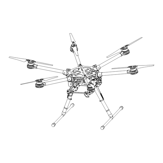
Summary of Contents for dji spreading wings s900
- Page 1 Spreading Wings S900 User Manual V1.0 2014.08...
-
Page 2: Disclaimer
This product and manual are copyrighted by DJI with all rights reserved. No part of this product or manual shall be reproduced in any form without the prior written consent or authorization of DJI. -
Page 3: Table Of Contents
ESC LED Specifications Gain Value Settings Soldering the ESC Remounting the Propellers Propeller Precautions Using the Propeller Holder Assembling Motor Vibration Absorbers Remounting the Landing Gear Servo Recalibrating Servo Travel Part List FCC Statements © 2014 DJI. All Rights Reserved. -
Page 4: Cautions
7. Use only 6S LiPo batteries for the power supply. 8. Ensure all output signals from M1 to M6 are in proper working order when using the DJI A2 flight control system to avoid damage or injury. -
Page 5: In The Box
Usage 2.0mm Hex Wrench, 2.5mm Hex Wrench Mounting screws. Thread Locker Fastening screws. Nylon Cable Tie Scissors Binding devices and wires. Cutting Pliers/Dykes Foam Double Sided Adhesive Tape Mounting receiver, controller and other modules. © 2014 DJI. All Rights Reserved. -
Page 6: Mounting The Landing Gear
Note the springs are 58.5mm before connecting to the center frame, and are stretched to 70mm when mounting is completed. It is recommended that the landing gear leg ring be placed about 30mm above the landing skid tube. 70mm 30mm © 2014 DJI. All Rights Reserved. -
Page 7: Mounting Frame Arms
4. Insert the M4×35 screw from the right of the frame arm (the thread is located on the left of the screw mount). Tighten each screw correctly. Over tightening may lead to connector abrasion. © 2014 DJI. All Rights Reserved. - Page 8 Then unscrew the 4 screws (M3×8 self-tapping, found under the center frame) of the round cover and remove it to gain access to the ESC and power cable installation area. 8. Plug each ESC signal cable into the slot near each arm on the center frame. © 2014 DJI. All Rights Reserved.
- Page 9 10. To ensure a reliable connection, rotate the screw until it is both tight and parallel to the connecting bracket. 11. Ensure all ESC cables, and power cables are correctly installed onto the center frame. ESC cables power cables © 2014 DJI. All Rights Reserved.
- Page 10 13. Double check all frame arms. Arms M1 and M2 are the forward facing (nose), arms M4 and M5 are the tail. Seen from the top, motors on arms M1, M3 and M5 rotate counter clockwise while those on arms M2, M4 and M6 rotate clockwise. © 2014 DJI. All Rights Reserved.
-
Page 11: Mounting Electronics And Wiring
Eight positions are reserved for mounting a flight control system, wireless video transmission module, receiver, and other accessories. The DJI A2 flight control system has been used here as an example. If using an A2, follow mounting and wiring instructions found in the A2 flight control system user manual. If using the DJI WK-M flight control system, please refer to the WK-M user manual for connections. - Page 12 6. The other reserved positions are indicated in the diagram below and can be used for mounting a receiver, LED flight indicator, iOSD module and wireless video transmission module. © 2014 DJI. All Rights Reserved.
- Page 13 Use glue to install the GPS bracket. Ensure it is firm and stable before every flight. Always test motors using the Assistant Software after installation. Refer to your flight control system user manual for details. © 2014 DJI. All Rights Reserved.
- Page 14 A2 Flight Controller the ESC Signal Outlet If using a DJI WK-M flight controller, you must use the wires that came with the WK-M. M1 through M6 correspond to each motor number. WKM Flight Controller the ESC Signal Outlet ©...
- Page 15 Right Servo Connector Left Servo Connector If right and left servo cables are reversed, the landing gear will not function properly. Connect all wires carefully and neatly to avoid cable damage caused by frame edges. © 2014 DJI. All Rights Reserved.
-
Page 16: Connecting Xt60 Ports On The Center Frame
1. Connect the PMU power cable to the XT60 connector on top of the bottom board. 2. Connect the landing gear control board cable to the XT60 connector on the bottom of the bottom board. 3. Other connectors can supply power for other DJI devices, as required. Installing Battery Soldering battery connectors AS150 spark-proof connectors are used. - Page 17 1. Attach battery to battery tray. Do not use an oversized battery. Maximum installation dimension is 80mm X 120mm X 200mm. 2. Connect the black connector and then the red connector to power on. Disconnect the red connector then black connector to power off. © 2014 DJI. All Rights Reserved.
-
Page 18: Setting Up The Landing Gear
If it flashes green slowly, re-calibrate the system according to instructions in “Recalibrating Servo Travel”. 5. Toggle the switch to the [Upper] position ONLY AFTER takeoff. 6. Toggle the switch to the [Lower] position for landing. © 2014 DJI. All Rights Reserved. - Page 19 Input Signal PWM (High-Pulse Width 800us~2200us) Working Current Max 1A@6S Output Signal PWM (Mid Position is 1520us) in 90Hz Working Temperature -20~70° C Output Voltage Total Weight 875g Servo Travel 150° (Minimum 120° ) © 2014 DJI. All Rights Reserved.
-
Page 20: Mounting The Gimbal
The connectors on gimbal should be removed for better performance, then the gimbal can be mounted to the lower connection points. Users of DJI Z15-5N / 7N gimbal, refer to the DJI Z15-5N / 7N Gimbal Mounting Notes (Page 21) for details. - Page 21 Check that the system’s center of gravity is on the line as shown in the diagram below. DJI Z15-5N / 7N Gimbal Mounting Notes Due to the size restriction of the Z15-5N / 7N gimbal, users should purchase extended landing gear legs (used with Z15-5N / 7N gimbal) to avoid damage and/or failure during the self-test.
-
Page 22: Appendix
Motor rotating Solid Red or Green On Motor rotating at full throttle position Solid Yellow On DJI ESCs are specifically designed for multi-rotors. When used with DJI autopilot systems parameters and travel ranges do not have to be calibrated. Specifications Frame... -
Page 23: Gain Value Settings
18min (@12000mAh & 6.8Kg Takeoff Weight) Working Environment Temperature -10° C ~ 40° C Gain Value Settings Basic Attitude Flight Control Pitch Roll Pitch Roll Vertical 110% 120% 220% 220% 110% 120% 160% 160% 160% 190% 190% 100% WooKong-M © 2014 DJI. All Rights Reserved. -
Page 24: Faq
Loose screws cannot be securely locked with thread locker. Propeller Precautions Torque markers on the screws and propeller covers will give you a visual cue to check whether the propellers are loose. Check the torque markers before every flight. © 2014 DJI. All Rights Reserved. -
Page 25: Using The Propeller Holder
After tightening the screws, the vibration absorbers may be twisted. If this is the case, hold the motor with your thumbs under the base plate and fingers on the top carbon plate, and squeeze the plates together to make the vibration absorbers flat and parallel with the plates. © 2014 DJI. All Rights Reserved. -
Page 26: Remounting The Landing Gear Servo
If the “R” and “L” servo cables are reversed, travel will not be measured correctly. Fix the connections and recalibrate the landing gear using the above steps. Landing gear travel has been pre-calibrated. Mechanical adjustment of the gear travel is not recommended. © 2014 DJI. All Rights Reserved. -
Page 27: Part List
S900 Frame Arm CW - Black S9010601CWB, S9010602, S9010603, S9010604, M3×12.3 (cheese) S900 Frame Arm CW – Red S9010701CWR, S9010702, S9010703, S9010704, M3×12.3 (cheese) S900 Motor Damping Unit S9010801, S9010802, M3×10.3 S900 Motor Mount Carbon Board S9011001, M3×4.5 © 2014 DJI. All Rights Reserved. - Page 28 S9012401G, S9012402, M3×12.3 (cheese) S900 Propeller Pack S9012501CCW, S9012502CW, S9012503, M3×12.3 (hexagan) Center Frame S9020301 M2.5x8 (cheese) S9021502 S9021503/ S9032703 M3x6.5 S9021501 S9020302 S9020901 M3x8 (self-tapping) S9021201L S9021202R S9021203/ S9021101 S9021401 M2.5x8 (cheese) M3x6.5 © 2014 DJI. All Rights Reserved.
-
Page 29: Landing Gear
M2.5x8 (socket cap) S9031813 M3x6.8 M2.5x8 (socket cap) S9032001 S9032601 S9032002 S9032602 Caution (1) Parts within the dotted box are mirrored against each other. S9032603 Except for S9031814 and S9031815. S9032606 M3x22 (socket cap) S9032604 © 2014 DJI. All Rights Reserved. - Page 30 S9033301, S9033302, S9033303, S9033304, S9033305, Mounting S9033306, S9033307, S9033308, S9033309, S9033310, Accessories S9033311, S9033312, S9033313, S9033314, M2.5×5, M2.5×13, M2.5×8 (cheese) Miscellaneous S9020201 S9020202 S9032701 S9032702 S9020103 S9020104 S9033401 Caution: This part is used with Z15-5N / 7N gimbal. © 2014 DJI. All Rights Reserved.
-
Page 31: Fcc Statements
Operation of this equipment in a residential area is likely to cause harmful interference in which case the user will be required to correct the interference at his own expense. © 2014 DJI. All Rights Reserved. - Page 32 User manual is subject to change without prior notice. You may visit DJI offical website to obtain the latest version of user manual. http://www.dji.com/product/spreading-wings-s900 © 2014 DJI. All Rights Reserved.
Need help?
Do you have a question about the spreading wings s900 and is the answer not in the manual?
Questions and answers