Goodman GME95 Technical Manual
96% gas furnace
Hide thumbs
Also See for GME95:
- Installation instructions manual (56 pages) ,
- Installation instructions manual (52 pages)
Advertisement
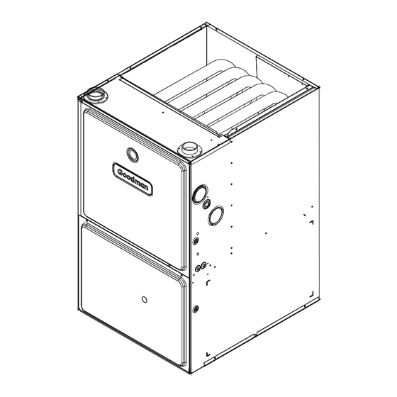
40"
•
Refer to Service Manual RS6610004 for installation, operation, and troubleshooting information.
•
All safety information must be followed as provided in the Service Manual.
•
Refer to the appropriate Parts Catalog for part number information.
•
Model numbers listed on page 3.
This manual is to be used by qualified, professionally trained HVAC technicians only.
Goodman does not assume any responsibility for property damage or personal
injury due to improper service procedures or services performed by an unqualified
person.
Copyright © 2011, 2013 Goodman Manufacturing
TECHNICAL MANU
TECHNICAL MANU
TECHNICAL MANU AL
TECHNICAL MANU
TECHNICAL MANU
GME95
96% Gas Furnace
UP TO
Company, L.P.
AL
AL
AL
AL
RT6612024r2
August 2013
Advertisement
Table of Contents

Related Manuals for Goodman GME95


Summary of Contents for Goodman GME95
- Page 1 Model numbers listed on page 3. This manual is to be used by qualified, professionally trained HVAC technicians only. RT6612024r2 Goodman does not assume any responsibility for property damage or personal August 2013 injury due to improper service procedures or services performed by an unqualified person.
-
Page 2: Product Identification
Maytag Corporation or its related companies and is used under license to Goodman Company, L.P., Houston, TX. All rights reserved. - Page 3 WARNING that is not design certified by damage, personal injury, or death, Goodman for use with this unit. do not store combustible materials or use gasoline or Serious property damage, personal injury, reduced unit other flammable liquids or vapors in the vicinity of this performance and/or hazardous conditions may result appliance.
-
Page 4: Product Design
3. Installer must supply the following gas line fittings, de- General Operation pending on which entrance is used: The GME95 furnaces are equipped with an electronic igni- Left -- Two 90º Elbows, one close nipple, straight pipe. tion device used to light the burners and an induced draft blower to exhaust combustion products. -
Page 5: Component Identification
COMPONENT IDENTIFICATION Upflow/Horizontal 1 Gas Valve 17 Electrical Connection Inlets (Alternate) 2 Gas Line Entrance (Alternate) 18 Coil Front Cover Pressure Tap 3 Pressure Switch 19 Coil Front Cover Drain Port 4 Gas Manifold 20 Drain Line Penetrations 5 Combustion Air Intake Connection / “Coupling” 21 Drain Trap 6 Hot Surface Igniter 22 Blower Door Interlock Switch... - Page 6 COMPONENT IDENTIFICATION GME95*****XA*...
- Page 7 PRODUCT DESIGN...
- Page 8 PRODUCT DESIGN AUXILIARY LIMIT SWITCHES Part Number 10123535 10123519 Open Setting (°F) GME950403BXA* GME950603BXA* GME950805CXA* GME951005DXA* ROLLOUT LIMIT SWITCHES Part Number 10123533 10123517 Open Setting (°F) GME950403BXA* GME950603BXA* GME950805CXA* GME951005DXA* PRIMARY LIMIT Part Number 0130M00063 20162904 Open Setting (°F) GME950403BXA* GME950603BXA* GME950805CXA* GME951005DXA*...
- Page 9 These coils are available in both cased and uncased models (with the option of a field installed TXV expansion device). These 95%+ furnaces match up with the existing Amana ® brand coils as shown in the chart below. ® Coil Matches (for Goodman units using R22 and R-410A): 1824 EXPANSION REVISION...
- Page 10 PRODUCT DESIGN Thermostats: NOTE: Complete lineup of thermostats can be found in the Thermostat Specification Sheets. Filters: Filters are required with this furnace and must be provided by the installer. The filters used must comply with UL900 or CAN/ULCS111 standards. Installing this furnace without filters will void the unit warranty. Upflow Filters This furnace has provisions for the installation of return air filters at the side and/or bottom return.
- Page 11 FURNACE SPECIFICATIONS GME95 GME95 GME95 GME95 GME95 MODEL 0 403BXA* 0603BXA* 0805CXA* 1 005DXA* Btuh Input (US) 40,000 60,000 80,000 10 0,000 Output (US) 38,400 57,700 76,900 96,100 Input (CAN) 40,000 60,000 80,000 10 0,000 Output (CAN) 38,400 57,700 76,900 96,100 A.F.U.E.
-
Page 12: Blower Performance Specifications
BLOWER PERFORMANCE SPECIFICATIONS (CFM & TEMPERATURE RISE VS. EXTERNAL STATIC PRESSURE) EXTERNAL STATIC PRESSURE (Inches Water Column) Model Tons -------------- Motor AC at Heating Speed Speed 0.5" As Shipped CFM RISE CFM RISE CFM RISE CFM RISE CFM RISE CFM T1 - YELLOW T2 - RED GME950403BX*... - Page 13 BLOWER PERFORMANCE SPECIFICATIONS...
-
Page 14: Wiring Diagrams
WIRING DIAGRAMS GME95*****XA* GAS VALVE Wiring is subject to change, always refer to the wiring diagram on the unit for the most up-to-date wiring.
Need help?
Do you have a question about the GME95 and is the answer not in the manual?
Questions and answers