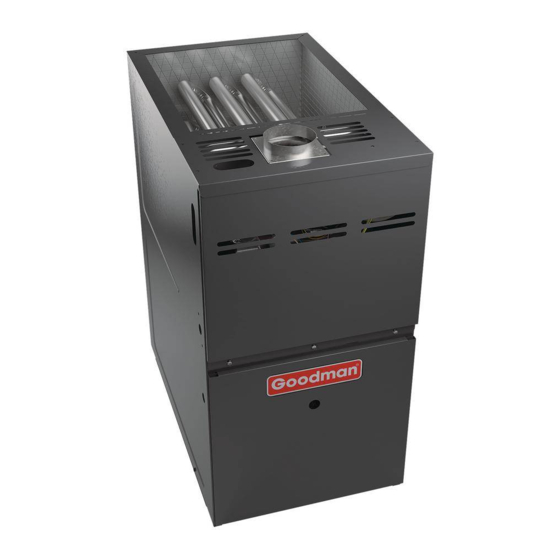
Goodman GMES80 Series Service And Troubleshooting

Goodman GMES80 Series Service And Troubleshooting

80% single stage gas furnaces

Advertisement

Service and Troubleshooting
GMES80, AMES80, GCES80, ACES80, VMES80, VCES80 & Accessories
This manual is to be used by qualified, professionally
trained HVAC technicians only. Goodman does not assume
any responsibility for property damage or personal injury
due to improper service procedures or services performed
by an unqualified person.
Pride and workmanship go into every product to provide
our customers with quality products. It is possible, however,
that during its lifetime a product may require service.
Products should be serviced only by a qualified service
technician who is familiar with the safety procedures
required in the repair and who is equipped with the proper
tools, parts, testing instruments and the appropriate service
manual. REVIEW ALL SERVICE INFORMATION IN THE
APPROPRIATE SERVICE MANUAL BEFORE
BEGINNING REPAIRS.
Only personnel that have been trained to install, adjust, service or
repair(hereinafter, "service") the equipment specified in this manual
should service the equipment. The manufacturer will not be
responsible for any injury or property damage arising from improper
service or service procedures. If you service this unit, you assume
responsibility for any injury or property damage which may result. In
addition, in jurisdictions that require one or more licenses to service
the equipment specified in this manual, only licensed personnel should
servise the equipment.
Improper installation, adjustment, servicing or repair of the equipment
specified in this manual, or attempting to install, adjust, service or
repair the equipment specified in this manual without proper training
may result in product damage, property damage, personal injury or
death.
PROP 65 WARNING
FOR CALIFORNIA CONSUMERS
Cancer and Reproductive Harm -
www.P65Warnings.ca.gov
80% Single Stage Gas Furnaces
WARNING
WARNING
Copyright ©
2019-2020 Goodman Manufacturing Company, L.P.
is a registered trademark of Maytag Corporation or its related companies and is used under license.
®
IMPORTANT INFORMATION ............................................ 2
PRODUCT IDENTIFICATION ........................................... 4
SYSTEM OPERATION ...................................................... 6
SCHEDULED MAINTENANCE ....................................... 25
SERVICING ..................................................................... 27
ACESSORIES ................................................................. 45
TROUBLESHOOTING CHART ....................................... 48
WIRING DIAGRAMS ....................................................... 51
0140M00517-A
All rights reserved.

TABLE OF CONTENTS

RS6621003r3
April 2020

Advertisement

Table of Contents
loading

Summary of Contents for Goodman GMES80 Series

  • Page 1: Table Of Contents

    GMES80, AMES80, GCES80, ACES80, VMES80, VCES80 & Accessories This manual is to be used by qualified, professionally TABLE OF CONTENTS trained HVAC technicians only. Goodman does not assume any responsibility for property damage or personal injury IMPORTANT INFORMATION ..........2 due to improper service procedures or services performed PRODUCT IDENTIFICATION ...........
  • Page 2: Important Information

    IMPORTANT INFORMATION IMPORTANT NOTICES FOR CONSUMERS AND SERVICERS RECOGNIZE SAFETY SYMBOLS, WORDS AND LABELS Pride and workmanship go into every product to provide our customers with quality products. It is possible, however, that during its lifetime a product may require service. Products should be serviced only by a qualified service technician who is familiar with the safety procedures required in the repair and who is equipped with the proper tools, parts, testing in-...
  • Page 3 IMPORTANT INFORMATION CO can cause serious illness including permanent brain damage or death. B10259-216 Advertencia especial para la instalación de calentadores ó manejadoras de aire en áreas cerradas como estacionamientos ó cuartos de servicio. Las emisiones de monóxido de carbono pueden circular a través del aparato cuando se opera en cualquier modo.
  • Page 4: Product Identification

    The model and manufacturing number are used for positive identification of component parts used in manufacturing. Please use these numbers when requesting service or parts information. Furnace Nomenclature Brand Minor Revision A- Amana® G- Goodman® A - Initial Release V- GMC® B - 1st Revision Configuration...
  • Page 5 ACES800805C* Exchanger. Comes in A , B & C Cab sizes. ACES801005C* *MES800403A* *MES800603A* Goodman Brand 80% Gas furnace. Multi-speed ECM *MES800603B* blower motor. Can be installed in Up-flow , horizontal Left & right positions. Left or Right side *MES800604B* Gas entry.
  • Page 6: System Operation

    SYSTEM OPERATION 8. Circulator blower is de-energized following a fixed forty NORMAL SEQUENCE OF OPERATION five (65) second cool off delay period. Power Up 9. Furnace awaits next call from thermostat. 1. 115 VAC power applied to furnace. Fan Only Mode 2.
  • Page 7 SYSTEM OPERATION HEATING - Abnormal Operation 5. Open Primary Limit. If the limit control opens, the air circulator blower will be turned on until the limit closes. The The following presents the probable causes of questionable induced draft blower will turn off for 5 seconds then turn furnace operation and how to fix them.
  • Page 8 O PREVENT PERSONAL INJURY OR DEATH DUE TO IMPROPER INSTALLATION, instructions. ADJUSTMENT, ALTERATION, SERVICE OR MAINTENANCE, REFER TO THIS MANUAL. OR ADDITIONAL ASSISTANCE OR INFORMATION, CONSULT A Goodman & Amana 80% furnaces are ETL certified ® QUALIFIED INSTALLER, SERVICE AGENCY OR THE GAS SUPPLIER. appliances and are appropriate for use with natural or propane gas.
  • Page 9 SYSTEM OPERATION Location Requirements and Considerations hydrochloric acid cements and glues WARNING antistatic fabric softeners for clothes dryers and masonry acid washing materials • Seal off a non-direct vent furnace if it is installed near O PREVENT POSSIBLE EQUIPMENT DAMAGE, PROPERTY DAMAGE, PERSONAL INJURY OR DEATH, THE FOLLOWING BULLET POINTS MUST BE OBSERVED an area frequently contaminated by any of the above WHEN INSTALLING THE UNIT.
  • Page 10 SYSTEM OPERATION Furnace Suspension f. After it has been determined that each appliance connected to the venting system properly vents when tested as outlined If suspending the furnace from rafters or joist, use 3/8” above, return doors, windows, exhaust fans, fireplace dampers threaded rod and 2”x2”x1/8”...
  • Page 11 SYSTEM OPERATION If this furnace is to be installed in the same space with other 9.3.2.2* Known Air Infiltration Rate Method. Where the air infil- tration rate of a structure is known, the minimum required volume gas appliances, such as a water heater, ensure there is an shall be determined as follows: adequate supply of combustion and ventilation air for the other appliances.
  • Page 12 SYSTEM OPERATION 9.3.3.1 Two Permanent Openings Method. Two permanent open- Chimney or Gas Vent ings, one commencing within 12 in. (300 mm) of the top and one commencing within 12 in. (300 mm) of the bottom, of the enclosure NOTE: The air duct openings shall be provided.
  • Page 13 SYSTEM OPERATION 9.3.8.4 Ducts shall not serve both upper and lower combustion (c) The minimum size of outdoor opening(s) shall be the full size of outdoor opening(s) calculated in accordance with air openings where both such openings are used. The separation 9.3.3, multiplied by the reduction factor.
  • Page 14 SYSTEM OPERATION When resizing any portion of the common venting system, Crown Wash use the appropriate table in Appendix G in the latest edition Roof Line of the National Fuel Gas Code NFPA 54/ANSI Z223.1. Upflow or Horizontal units are shipped with the induced Clay Tile Size Generally Clay Tile Size: 8"...
  • Page 15 SYSTEM OPERATION 10' or Less Proper Chimney Line, terminate with listed vent cap Termination? (Check 1) (Fix 1) 2' Min. 2' Min. 3' Min. Wall or Parapet Chimney channel free of solid and Change venting Chimney liquid fuel arrangements appliances? (Fix 2) (Check 2) 10' or Less...
  • Page 16 SYSTEM OPERATION Check 3 - Chimney Crown Condition. Flexible liners should be hung straight or nearly straight. If it is spiraled in the chimney and in good condition, it should be Damage from condensate usually shows up first in the crown. rehung.
  • Page 17 SYSTEM OPERATION • Extremely cold weather heat loss, with an increased possibility of poor venting system performance. • Long vent connectors It is not acceptable to vent one appliance inside the B vent • Masonry chimneys with no air gap between the liner and and other appliances outside.
  • Page 18 SYSTEM OPERATION Even if none of those three conditions exist which require WARNING additional liner insulation, the installer may wish to consider it if: PON COMPLETION OF THE FURNACE INSTALLATION, CAREFULLY INSPECT THE • • The local climate is very cold. ENTIRE FLUE SYSTEM BOTH INSIDE AND OUTSIDE THE FURNACE TO ASSURE IT •...
  • Page 19 SYSTEM OPERATION A different pressure switch may be required at high altitude Natural Gas Capacity of Pipe regardless of the BTU/ft content of the fuel used. Refer to the In Cubic Feet of Gas Per Hour (CFH) product Specification Sheet or Technical Manual for a tabular Length of Nominal Black Pipe Size listing of appropriate altitude ranges and corresponding...
  • Page 20 SYSTEM OPERATION 10. Use listed gas appliance connectors in accordance with For satisfactory operation, propane gas pressure must be their instructions. Connectors must be fully in the same 11 inch WC at the furnace manifold with all gas appli ances room as the furnace.
  • Page 21 SYSTEM OPERATION When installing a propane storage tank, the contractor WARNING must consider proper tank sizing, safety, efficiency, ground characteristics and aesthetics. For a residential customer, the size may range from 100-1,000 gallons, depending on F THE INFORMATION IN THESE INSTRUCTIONS IS NOT FOLLOWED EXACTLY, A FIRE OR EXPLOSION MAY RESULT CAUSING PROPERTY DAMAGE, PERSONAL household use.
  • Page 22 SYSTEM OPERATION electrical disconnect must be provided at the furnace location. OPTIONAL ACCESORIES NOTE: Line polarity must be observed when making field connections. ELECTRONIC AIR CLEANER HUMIDIFIER N 90% FURNACE UPRIGHT UPFLOW INSTALLATIONS, THE DRAIN TRAP MUST BE MOUNTED ON THE OPPOSITE SIDE OF THE UNIT FROM THE JUNCTION 120 VAC BOX.
  • Page 23 SYSTEM OPERATION Upflow / Horizontal Minimum Recommended Filter Size^ Models *0403A* 1 - 16 X 25 Side or 1 - 14 X 24 Bottom Return *0603A* 1 - 16 X 25 Side or 1 - 14 X 24 Bottom Return *0604B* 1 - 16 X 25 Side or Bottom Return *0803B*...
  • Page 24 SYSTEM OPERATION a media air filter or electronic air cleaner can be used as the requested filter. Refer to the following minimum filter requirement charts for determination of the minimum filter area to ensure proper unit performance. COUNTERFLOW FILTER INSTALLATION This furnace has provisions for the installation of return air filters at the counterflow top return.
  • Page 25: Scheduled Maintenance

    SCHEDULED MAINTENANCE Maintenance WARNING Improper filter maintenance is the most common cause of inadequate heating or cooling performance. Filters should HIGH VOLTAGE be cleaned (permanent) or replaced (disposable) every two ISCONNECT POWER BEFORE SERVICING OR months or as required. It is the owner’s responsibility to keep INSTALLING THIS UNIT.
  • Page 26 SCHEDULED MAINTENANCE BURNERS To find the BTU input, multiply the number of cubic feet of gas consumed per hour by the heating value of the gas being WARNING used. (The calorific value of the gas being used is found by contacting your local utility.) HIGH VOLTAGE LECTRICAL COMPONENTS ARE CONTAINED IN BOTH...
  • Page 27: Servicing

    SERVICING CHECKING VOLTAGE ..........................32 CHECKING WIRING ........................... 32 S-3A THERMOSTAT AND WIRING ........................32 S-3B HEATING ANTICIPATOR ..........................32 CHECKING TRANSFORMER AND CONTROL CIRCUIT ............... 33 S-16A CHECKING AIR CIRCULATOR BLOWER MOTOR (MULTI-SPEED ECM MOTOR) ......33 S-200 CHECKING DUCT STATIC ......................... 34 S-201 CHECKING TEMPERATURE RISE ......................
  • Page 28 SERVICING As more and more electronic's are introduced to the Heating INCOMING POWER Trade, Polarization of incoming power and phasing of pri- mary to secondary voltage on transformers becomes more 120.00 0.00 important. Polarization has been apparent in the Appliance industry since the introduction of the three prong plug, however, the Heating Industry does not use a plug for incoming power, but is hard wired.
  • Page 29 SERVICING CUBIC FEET GAS RATE -- CUBIC FEET PER HOUR Size of Test Dial Size of Test Dial Seconds for Seconds for cu/ft cu/ft cu/ft cu/ft cu/ft cu/ft cu/ft cu/ft cu/ft cu/ft Revolution Revolution 1800 1636 1500 1385 1286 1200 1125 1059 1000...
  • Page 30 SERVICING Unsatisfactory Service Problem No Heat Heat POSSIBLE CAUSE Test Method DOTS IN ANALYSIS Remedy GUIDE INDICATE "POSSIBLE CAUSE" ● Pow er Failure Test Voltage ● Blow n Fuse Test Voltage ● Loose Connection Check Wiring ● Shorted or Broken Wires Check Wiring S-3A ●...
  • Page 31: Checking Voltage

    SERVICING S-1 CHECKING VOLTAGE CHECKING THERMOSTAT, WIRING AND ANTICIPATOR WARNING S-3A THERMOSTAT AND WIRING HIGH VOLTAGE WARNING ISCONNECT POWER BEFORE SERVICING OR CHANGING ANY ELECTRICAL WIRING. ULTIPLE POWER ISCONNECT POWER BEFORE SERVICING. SOURCES MAY BE PRESENT. AILURE TO DO SO MAY CAUSE PROPERTY DAMAGE, PERSONAL INJURY OR DEATH.
  • Page 32: Checking Transformer And Control Circuit

    SERVICING S-16 CHECKING AIR CIRCULATOR BLOWER Cooling Anticipator The cooling anticipator is a small heater (resistor) in the MOTOR thermostat. During the “OFF” cycle it heats the bimetal element helping the thermostat call for the next cooling cycle. WARNING This prevents the room temperature from rising too high before the system is restarted.
  • Page 33: Checking Duct Static

    SERVICING 4. Consult proper tables for the quantity of air. COOL MOTOR SPEED DIP SWITCH SETTING (S1-1, S1-2, S1-3) If the total external static pressure exceeds the minimum Position OFF OFF OFF ON OFF OFF ON ON OFF OFF ON OFF or maximum allowable statics, check for closed dampers, Motor registers, undersized and/or oversized poorly laid out duct...
  • Page 34: Checking Primary Limit Control

    SERVICING Style 1 drawing illustrates the Primary Limit used on the 80% furnaces. SUPPLY Style 1 WARNING HIGH VOLTAGE RETURN ISCONNECT POWER BEFORE SERVICING OR CHANGING ANY ELECTRICAL WIRING. ULTIPLE POWER SOURCES MAY BE PRESENT. AILURE TO DO SO MAY CAUSE PROPERTY DAMAGE, PERSONAL INJURY OR DEATH.
  • Page 35: S-301 Checking Auxiliary Limit Control

    SERVICING S-301 CHECKING AUXILIARY LIMIT CONTROL WARNING O AVOID POSSIBLE FIRE, ONLY RESET THE AUXILIARY LIMIT CONTROL ONCE. F IT SHOULD OPEN A SECOND TIME, A QUALIFIED SERVICER MUST DETERMINE WHY THE AUXILIARY LIMIT OPENED BEFORE RESETTING AGAIN. S-302 CHECKING FLAME ROLLOUT CONTROL A temperature activated manual reset control is mounted to BLOWER HOUSING the manifold assembly on 80% furnaces,...
  • Page 36: Induced Draft Blower Motor

    SERVICING S-304 CHECKING GAS VALVE (Redundant)  A combination redundant operator type gas valve which provides all manual and automatic control functions required for gas fired heating equipment is used. The valve provides control of main burner gas flow, pressure regulation, and 100 percent safety shut-off.
  • Page 37: Checking Gas Pressure

    SERVICING Orifices should be treated with care in order to prevent damage. They should be removed and installed with a box- WARNING end wrench in order to prevent distortion. In no instance should an orifice be peened over and redrilled. This will ISCONNECT ELECTRICAL POWER AND SHUT OFF GAS SUPPLY.
  • Page 38 SERVICING 4. Measure gas manifold pressure with burners firing. Adjust WARNING manifold pressure using the table below. Manifold Gas Pressure HIGH VOLTAGE Natural Gas 3.5" w.c. ISCONNECT ELECTRICAL POWER AND SHUT OFF GAS Propane Gas 10.0" w.c. SUPPLY BEFORE SERVICING OR INSTALLING THIS UNIT. ULTIPLE POWER SOURCES MAY BE PRESENT.
  • Page 39: S-308 Checking Hot Surface Ignitor

    SERVICING S-308 CHECKING HOT SURFACE IGNITOR WARNING 120V Mini Igniter Single Stage - furnaces use a 120V carbide mini igniter for ignition. (part# 20165703) or a HIGH VOLTAGE Silicon Nitride igniter (part# 0130F00008) The normal ISCONNECT ELECTRICAL POWER AND SHUT OFF GAS SUPPLY BEFORE SERVICING OR INSTALLING THIS UNIT.
  • Page 40: S-310 Checking Pressure Control

    SERVICING S-310 CHECKING PRESSURE SWITCH S-311 HIGH ALTITUDE APPLICATION (USA) The pressure switch a safety device to prevent the combustion Check your furnace rating plate to determine its rated altitude cycle from occurring with inadequate venting caused by a (either 4500 or 5500 ft). Do not attempt to increase the firing restricted or blocked vent pipe on the 80% and 90% furnaces.
  • Page 41: S-313 Checking Integrated Ignition Control Boards

    SERVICING S-313 C H E C K I N G I N T E G R AT E D I G N I T I O N CONTROL BOARDS NOTE: Failure to earth ground the furnace, reversing the neutral and hot wire connection to the line (polarity), or a high resistance connection in the neutral line may cause the control to lockout due to failure to sense flame.
  • Page 42 SERVICING PCBBF145 DIAGRAM 59-5240 REV.003 CR35 CR18 R175 CR19 CR13 CR15 R177 R176 CR36 R179 R178 FLAME CURRENT 1VDC=1UA R181 CR38 R110 R112 CR37 R111 R113 R121 R123 R115 R126 R125 R120 R151 R180 R150 R145 R149 R168 R170 R148 CR26 R118 R119...
  • Page 43: Checking Flame Sensor

    SERVICING S-314 CHECKING FLAME SENSOR A flame sensing device is used in conjunction with the ignition WARNING control module to prove combustion. If proof of flame is not present the control will de-energize the gas valve and “retry” INE VOLTAGE NOW PRESENT for ignition or lockout.
  • Page 44 SERVICING *MES80 / *CES80 Pressure Switch Trip Points And Usage Chart ID BLOWER Set Point on Max Make MODEL Pressure Switch Pressure Fall (PF) Pressure On Part# W.C. Rise W.C. *MES800403A* -0.70 ±0.06 -0.85 0130F00505 *MES800603A* -0.90 0130F00506 -0.75 ±0.07 *MES800603B* -0.75 ±0.07 -0.90...
  • Page 45: Acessories

    ACCESSORIES ® GOODMAN BRAND "S" Model Furnace Accessories MODEL NUMBER · · · · · · · · · GMES800403A** · · · · · · · · · GMES800603A** · · · · · · · · · GMES800604B** ·...
  • Page 46 ACCESSORIES GMC® BRAND "S" Model Furnace Accessories MODEL NUMBER · · · · · · · GMES800403A* · · · · · · · GMES800603A* · · · · · · · GMES800604B* · · · · · · · GMES800804B* ·...
  • Page 47 ACCESSORIES GMC® BRAND "S" Model Furnace Accessories MODEL NUMBER · · · · · · · VMES800403AN · · · · · · · VMES800603AN · · · · · · · VMES800604BN · · · · · · · VMES800804BN ·...
  • Page 48: Troubleshooting Chart

    TROUBLESHOOTING Associated Symptoms of Abnormal Fault Description(s) Possible Causes Corrective Action Cautions and Notes Operation LED Code • Furnace fails to operate. • No 115 volt power • Manual disconnect • Assure 115 and 24 volt • Turn power OFF •...
  • Page 49 TROUBLESHOOTING • Circulator blower runs • Primary or auxiliary • Faulty primary or • Check primary/ • Turn power OFF prior continuously. No furnace operation. limit circuit is open. auxiliary limit switch. auxiliary limit. to repair. • Integrated control • Insufficient conditioned Replace if necessary.
  • Page 50 TROUBLESHOOTING • Furnace not operating. • Open Fuse / No 24V • High voltage surge • Replace the Fuse. • Verify line voltage • Integrated control module power to integrated blows off the fuse. supply is turned off diagnostic LED is flashing TEN control module before proceeding (10) flashes.
  • Page 51: Wiring Diagrams

    WIRING DIAGRAMS *MES80 / *CES80 CIRCULATOR BLOWER INDUCER HEAT COOL PARK PARK ROLLO UT SWITCH XFMR 24 VAC XFMR .0005 COMPRESSOR CONTACTOR FACTORY COIL JUMPER FACTORY JUMPER THERMOSTAT FLAME SENSOR PROBE HIGH LIMIT LIMIT IGNITOR VALVE PRESSURE SWITCH TYPICAL SCHEMATIC *MES80 / *CES80 MODEL FURNACES WR 50T55-289 INTEGRATED IGNITION CONTROL Wiring is subject to change.
  • Page 52 WIRING DIAGRAMS *MES80/*CES80 (with PCBBF161 Control Board) WARNING:DISCONNECT POWER BEFORE SERVICING.WIRING TO UNIT MUST BE PROPERLY POLARIZED AND GROUNDED. INTEGRATED HUMIDIFIER CONTROL MODULE GND (8) MVC (9) VALVE MV (12) ID BLOWER PRESSURE AUXILIARY SWITCH LIMIT CONTROLS PS (10) PSO (4) MICRO HLI (7) HLO (1)
  • Page 53 GOODMAN BRAND ® AMANA BRAND ® is a registered trademark of Maytag Corporation or its related companies and is used under license. ® All rights reserved. Copyright © 2019-2020 Goodman Manufacturing Company, L.P.

Table of Contents