Superior BC36MH Installation Instructions Manual
Superior wood burning fireplaces installation instructions
Hide thumbs
Also See for BC36MH:
- Installation instructions manual (20 pages) ,
- Installation instructions manual (20 pages) ,
- Care and operation instructions manual (8 pages)
Table of Contents
Advertisement
RETaIN ThEsE INsTRuCTIONs
FOR FuTuRE REFERENCE
INsTaLLaTION
INsTRuCTIONs
WOOD BURNING fIReplaces
mODels Bc36mH & BcD36mH
36" Wood Burning Fireplaces
P/N 700,039M REV. NC 07/2007
MODELS
BC36MH
This installation manual will enable you to obtain a safe, efficient
and dependable installation of your fireplace system. Please
read and understand these instructions before beginning your
installation.
Do not alter or modify the fireplace or its components under any
circumstances. Any modification or alteration of the fireplace
system, including but not limited to the fireplace, chimney
components and accessories, may void the warranty, listings
and approvals of this system and could result in an unsafe and
potentially dangerous installation.
IMPORTaNT! TO assuRE PROPER aLIgNMENT OF gLass
dOORs: INsTaLL ThIs FIREPLaCE IN a squaRE aNd PLuMB
CONdITION, usINg shIMs as NECEssaRy aT sIdEs aNd/OR
BOTTOM.
BCD36MH
OTL Report No.
116-F-35-2
Advertisement
Table of Contents

Subscribe to Our Youtube Channel
Related Manuals for Superior BC36MH


Summary of Contents for Superior BC36MH
- Page 1 INsTaLLaTION INsTRuCTIONs WOOD BURNING fIReplaces mODels Bc36mH & BcD36mH 36" Wood Burning Fireplaces P/N 700,039M REV. NC 07/2007 MODELS BC36MH BCD36MH This installation manual will enable you to obtain a safe, efficient and dependable installation of your fireplace system. Please read and understand these instructions before beginning your installation.
-
Page 2: Table Of Contents
Each of these topics will of this Superior appliance for use with this be covered in thorough detail throughout this fireplace to cook or warm food. -
Page 3: Introduction
This is important to pre- model BC36MH. vent possible personal injury or fire hazard. may create a fire hazard and void The grate included properly positions the fire and the limited warranty. -
Page 4: Assembly Outline
WaRNINg Insulate Joists Same As Ceiling do not obstruct the collar open- ings around the base of the chim- ney at the top of the fireplace. Hearth do not insulate the chimney Draft Stops enclosure cavity with blown or fill type insulation materials. Hearth Firestop assEMBLy OuTLINE... -
Page 5: Assembly Steps
(blower is optional for model Hearth The firestop thimble must extend completely Extension BC36MH). though the roof cavity to the outermost plane 1" (25 mm) Space 4. Install the outside combustion air kit. of the roof (See Figures 16, 17 and 18). - Page 6 Optional Floor Bracket 1 Z\x" Metal Safety Strips Ceiling Framing Framing dimensions for Ceiling Figure 8 Roof Framing Framing dimensions for Ceiling Framing dimensions for Roof Inches (millimeters) Inches Flue Type FTF8 at 1" (USA) Blocking Pitch FTF8, Vertical 14-1/2" 14-1/2" (368 mm) (368 mm) 0/12...
-
Page 7: Fireplace Specifications
Back Wall of Chase/Enclosure FOAK-6 Outside Product Reference Information Including Finising Materials if any Air Kit Cat. Model Ship. Ship. Volume h4630 BC36Mh 175 lb. 20.7 cu. ft. (See Note **) h4631 BCd36Mh 180 lb. 20.7 cu. ft. Framing dimensions Rough Header... -
Page 8: Installing The Chimney System
step 4. Fireplace should be secured to side In new construction, to determine chimney center Room Above framing members using the nailing line, use plumb line from roof or ceiling above tabs at the top and bottom of the fireplace to center of flue collar on fireplace. fireplace front face. - Page 9 Install the Model FTF8-S4 stabilizer by fitting Outer pipe section installs in just the opposite WaRNINg inner section down into respective section of way; the lanced end goes down and each new proceeding flue pipe and locking outer stabilizer section goes OVER the outside of the previous do not allow insulating materials to section into place over the outer chimney pipe.
-
Page 10: Ten Foot Rule Summary
step 7. Secure flashing by nailing along the Note: If chimney extends more than 8' above 3. Center outer locking section over outer flue perimeter into roof using 8d nails or roof surface, guy wires are also recommended. pipe. Push down until locking tabs are firmly equivalent fasteners. -
Page 11: Special Offset Instructions
FTF8 ChIMNEy COMPONENT Maximum offset of chimney system is 30°. Room Above Two offsets must not be assembled to form CaLCuLaTIONs a 60° offset. However, two sets of offset and F8FS30 1" Min. return elbows may be used on a single flue Firestop Spacer The minimum installed height of the completed Air Space... -
Page 12: Vertical Elevation Chart
FTF8 VERTICaL ELEVaTION ChaRT height Of Chimney Number Of FTF8 height Of height Of Chimney Number Of FTF8 height Of Only Chimney Components Chimney Only Chimney Components Chimney Only Only Inches Feet/Inches 12" 18" 24" 36" 48" Meters Inches Feet/Inches 12"... -
Page 13: Offset Elevation Chart
FTF8 OFFsET ELEVaTION ChaRT FTF8-s4 Number of FTF8 Chimney sections Offset Offset stabilizer Offset Offset 12" 18" 24" 36" 48" (inches) (inches) (meters) (meters) – 0.10 0.40 – 0.23 0.63 – 0.31 0.76 – 0.36 0.85 – 0.38 0.89 – 0.44 0.98 –... -
Page 14: Installing Offsets
BCD36MH and is available ceiling cut. This fireplace is not intended as an option for model BC36MH. The optional step 2. Proceed by using the Straight Up In- Blower Kit can be installed prior to or after... -
Page 15: Combustion Air Kits
Always check local building codes. Instal- CauTION Combustion Air lation of the BFK36 Blower Kit must comply Actuator with local regulations as well as the National When using the decorative gas Electric Code. appliance, the fireplace damper must be set in the fully open Combustion air Kits position. -
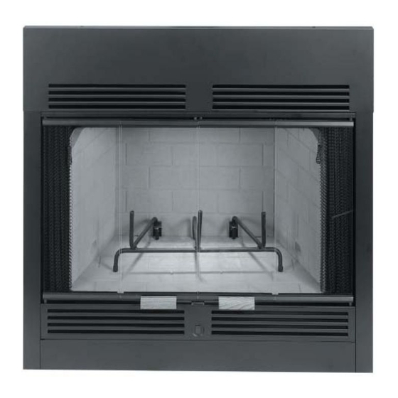
Page 16: Glass Doors
hearth Extensions and Wall shields Note: A 1" air space must be preserved for all FIREPLaCE FINIshEs combustible materials extending for any con- tinuous length adjacent to the chimney. A hearth extension must be installed with all Mantels and Trim fireplaces. - Page 17 Wall Shield Required Where Less Than 12". Adjacent Wall Is hearth Extension dimensions Never Allowed Closer Than 7". 24" 16" 30" Protected 8" Side Wall 30" 46" Note: To convert inches to millimeters divide by .03937. Figure 42 Methods of determining hearth Extension and Wall shield Listed Material Equivalents - To determine the thickness required for the alternate...
-
Page 18: Finish Requirements
The accessory parts and components shown on accomplish this? Pages 18 and 19 are to be used only with your If common brick is used so that the 3 1/2” BCD36MH or BC36MH fireplace system. 3-3/4" dimension is the height, “R” for the common brick becomes:... - Page 19 INsTaLLaTION COMPONENTs storm Collar 63L59 storm Collar (12 pack) 94L77 FsC-B-12 Firestop spacer (Flat) (single Pack) 63L29 F8Fs Firestop spacer (Flat) (12 Pack) 94L76 F8Fs-12 63L10 FTF8-12 63L13 FTF8-18 h0522 FTF8-24 63L14 FTF8-36 Chimney section 63L15 FTF8-48 19M55 F8F6Mh stabilizer 63L25 FTF8-s4 19M56...
- Page 20 The manufacturer reserves the right to make changes at any time, without notice, in design, materials, specifications, prices and also to discontinue colors, styles and products. Consult your local distributor for fireplace code information. Printed in U.S.A. © 2007 by LHP 1110 West Taft avenue P/N 700,039M REV.
Need help?
Do you have a question about the BC36MH and is the answer not in the manual?
Questions and answers