Table of Contents
Advertisement
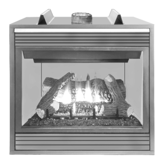
B-500 MODEL SHOWN
f i r e - p a r t s . c o m
RETAIN THESE INSTRUCTIONS
WARNING: IF THE INFORMATION IN THIS MANUAL
IS NOT FOLLOWED EXACTLY, A FIRE OR EXPLO-
SION MAY RESULT CAUSING PROPERTY DAM-
AGE, PERSONAL INJURY OR LOSS OF LIFE.
FOR YOUR SAFETY: Do not store or use gasoline
or other flammable vapors or liquids in the vicin-
ity of this or any other appliance.
FOR YOUR SAFETY: What to do if you smell gas:
• DO NOT light any appliance.
• DO NOT touch any electrical switches.
• DO NOT use any phone in your building.
• Immediately call your gas supplier from a
neighbor's phone.
Follow your gas suppliers instructions.
• If your gas supplier cannot be reached, call the
fire department.
Installation and service must be performed by a
qualified installer, service agency or the gas
supplier.
FOR FUTURE REFERENCE
WH Report No. J3008600
NOTE: DIAGRAMS & ILLUSTRATIONS NOT TO SCALE.
HOMEOWNER'S CARE AND
OPERATION INSTRUCTIONS
500/600/800 SERIES
B-VENTED GAS APPLIANCES
P/N 725,031M REV. E 11/2004
MODELS
M
l i
v i l
M
o
e d
B
5 -
0 0
C
M
B
5 -
0 0
C
M
B
6 -
0 0
C
M
B
6 -
0 0
C
M
B
8 -
0 0
C
M
B
8 -
0 0
C
M
AVERTISSEMENT: ASSUREZ-VOUS DE BIEN SUIVRE
LES INSTRUCTIONS DONNÉ DANS CETTE NOTICE POUR
RÉDUIRE AU MINIMUM LE RISQUE D'INCENDIE OU
POUR ÉVITER TOUT DOMMAGE MATÉRIEL, TOUTE
BLESSURE OU LA MORT.
POUR VOTRE SÉCURITÉ: Ne pas entreposer ni utiliser
d'essence ni d'autre vapeurs ou liquides inflammables
dans le voisinage de cet appareil ou de tout autre
appareil.
POUR VOTRE SÉCURITÉ: Que faire si vous sentez une
odeur de gaz:
• Ne pas tenter d'allumer d'appareil.
• Ne touchez à aucun interrupteur. Ne pas vous servir
des téléphones se trouvant dans le batiment où
vous vous trouvez.
• Evacuez la piéce, le bâtiment ou la zone.
• Appelez immédiatement votre fournisseur de gaz
depuis un voisin. Suivez les instructions du
fournisseur.
• Si vous ne pouvez rejoindre le fournisseur de gaz,
appelez le service dos incendies.
L'installation et service doit être exécuté par un qualifié
installeur, agence de service ou le fournisseur de gaz.
B-VENT
t l o
E
e l
r t c
n o
c i
s l
M
o
e d
s l
N
B
5 -
0 0
C
E
N
P
B
5 -
0 0
C
E
P
N
B
6 -
0 0
C
E
N
P
B
6 -
0 0
C
E
P
N
B
8 -
0 0
C
E
N
P
B
8 -
0 0
C
E
P
1
Advertisement
Table of Contents
Troubleshooting

Subscribe to Our Youtube Channel
Related Manuals for Superior B-500CEN


Summary of Contents for Superior B-500CEN
- Page 1 HOMEOWNER'S CARE AND OPERATION INSTRUCTIONS B-VENT 500/600/800 SERIES B-VENTED GAS APPLIANCES P/N 725,031M REV. E 11/2004 MODELS v i l t l o r t c B-500 MODEL SHOWN f i r e - p a r t s . c o m RETAIN THESE INSTRUCTIONS FOR FUTURE REFERENCE AVERTISSEMENT: ASSUREZ-VOUS DE BIEN SUIVRE...
-
Page 2: Table Of Contents
Never obstruct In selecting this SUPERIOR B-Vent Gas Appliance you have chosen the finest and most the front openings of the appliance. dependable fireplace to be found anywhere. A beautiful, prestigious, alternative to a wood burning fireplace. -
Page 3: Operation/Care Of Your Appliance
Ne pas se servir de cet appareil s'il a été plongé WARNING: FAILURE TO COMPLY dans l'eau, complètement ou en partie. Appeler WITH THE INSTALLATION AND OPER- un technicien qualifié pour inspecter l'appareil et ATING INSTRUCTIONS PROVIDED IN remplacer toute partie du système de contrôle et THIS DOCUMENT WILL RESULT IN AN toute commande qui ont été... -
Page 4: Variable Flame Adjustment
If your millivolt appliance is equipped with an optional remote wall switch or remote control kit Inlet Pressure Port Variable Flame Height Adjustment and the pilot is lit, the appliance main burner may Manifold Pressure Port be turned on and off with the wall switch or remote control. -
Page 5: Outside Combustion Air Control
Outside Combustion Air Controls Manually-Reset Safety Limit Switch WARNING: DO NOT OPERATE THE SHUTOFF LEVER UNLESS A COM- This appliance is equipped with a manually- Many appliances are equipped, when installed, PLETE OUTSIDE COMBUSTION AIR reset blocked flue safety limit switch. Refer to with an outside (make-up air) vent system that Figure 6 on page 7 for its location. -
Page 6: Maintenance Schedule
Maintenance Schedule Annually (Before the onset of the Burning Season) Maintenance Task Accomplishing Person Procedure Inspecting/Cleaning Burner, Logs Qualified Service Technician Inspect valve and ensure it is properly operat- and Controls ing. Check piping for leaks. Vacuum the control compartment, fireplace logs and burner area. Check Flame Patterns and Flame Height Qualified Service Technician Refer to Figures 12 (B-500), 13 (B-600) or... -
Page 7: Maintenance
Refer to the maintenance schedule for main- THE GLASS DOOR OF THIS APPLIANCE tenance tasks, procedures, periodicity and Wire MUST ONLY BE REPLACED AS A COMPLETE by whom they should be performed. Always Termianls UNIT AS PROVIDED BY THE MANUFAC- verify proper operation of the appliance after TURER. -
Page 8: Burner Adjustments
Electronic Appliance Checkout Burner Adjustments SIT and Honeywell Millivolt Appliance Checkout To light the burner, refer to the lighting instruc- Note - The air shutter for the burner primary air tions on page 15 and 16 . Ensure the ignitor The pilot flame should be steady, not lifting or opening is factory-set. -
Page 9: Log Placement
Log Placement Carefully position the ceramic fiber logs and twigs over the burner as shown in Figures 12 (B-500), 13 (B-600) or 14 (B-800) . For more detailed placement instructions, refer to the LOG PLACEMENT GUIDE accompanying this document. WARNING: LOGS GET VERY HOT AND WILL REMAIN HOT UP TO ONE HOUR Proper twig placement is critical to prevent sooting. -
Page 10: Wiring Diagrams
WIRING DIAGRAMS Wiring diagrams are provided here for reference purposes only. This information is also provided on schematics attached directly to the appliance on a pullout panel located within the control compartment. CAUTION: LABEL ALL WIRES PRIOR TO DISCONNECTION WHEN SERVICING CONTROLS. WIRING ERRORS CAN CAUSE IMPROPER AND DANGEROUS APPLIANCE OPERATION. -
Page 11: Accessory Components
ACCESSORY COMPONENTS Forced Air Blower Kits -Single Speed 80L84 FBK-100 -Variable Speed with wall-mountable switch 80L85 FBK-200 Remote Control System (Deluxe) H0251 RCL-T Remote Control System (Standard) H0249 -Variable Speed with unit- or wall-mountable switch 80L86 FBK-250 Deluxe Remote Control System Standard Remote Control System Forced Air Kit The Model RCL-T (Deluxe) Remote Control... - Page 12 ACCESSORY COMPONENTS CONTINUED s t i s t i s t i Clean faced panel kits are available to convert These hood kits replace the standard hood the standard louvered fireplaces to radiant mod- that comes with these fireplaces. els which are more suited for finishing around the firebox opening with non-combustible The brickade liner kits include tan stamped f i r e - p a r t s .
-
Page 13: Lighting Instructions - Millivolt
LIGHTING INSTRUCTIONS – HONEYWELL AND SIT MILLIVOLT GAS VALVE FOR YOUR SAFETY READ BEFORE LIGHTING WARNING: IF YOU DO NOT FOLLOW THESE INSTRUCTIONS EXACTLY, A FIRE OR EXPLOSION MAY RESULT CAUSING PROPERTY DAMAGE, PERSONAL INJURY OR LOSS OF LIFE. A. This appliance has a pilot which must be lighted with a piezo •... - Page 14 INSTRUCTIONS D’ALLUMAGE – VANNE GAZ MILLIVOLT HONEYWELL ET SIT POUR VOTRE SÉCURITÉ, LISEZ CES INSTRUCTIONS AVANT L’ALLUMAGE AVERTISSEMENT : SI VOUS NE SUIVEZ PAS CES INSTRUCTIONS À LA LETTRE, IL POURRAIT S’EN SUIVRE UN INCENDIE OU UNE EXPLOSION CAUSANT DES DOMMAGES MATÉRIELS, DES BLESSURES CORPORELLES OU MÊME DES PERTES DE VIE. A.
-
Page 15: Lighting Instructions - Electronic
LIGHTING INSTRUCTIONS — ELECTRONIC FOR YOUR SAFETY READ BEFORE LIGHTING WARNING: IF YOU DO NOT FOLLOW THESE INSTRUCTIONS EXACTLY, A FIRE OR EXPLOSION MAY RESULT CAUSING PROPERTY DAMAGE, PERSONAL INJURY OR LOSS OF LIFE. A. When lighting the appliance, follow these instructions •... - Page 16 INSTRUCTIONS D’ALLUMAGE — ELECTRONIC POUR VOTRE SÉCURITÉ, LISEZ CES INSTRUCTIONS AVANT L’ALLUMAGE AVERTISSEMENT: SI VOUS NE SUIVEZ PAS CES INSTRUCTIONS À LA LETTRE, IL POURRAIT S’EN SUIVRE UN INCENDIE OU UNE EXPLOSION CAUSANT DES DOMMAGES MATÉRIELS, DES BLESSURES CORPORELLES OU MÊME DES PERTES DE VIE. A.
-
Page 17: Troubleshooting Guide - Millivolt
TROUBLESHOOTING THE MILLIVOLT GAS CONTROL SYSTEM Note: Before troubleshooting the gas control system, be sure external gas shut off valve (located at gas supply inlet) is in the “ON” position. Important: Valve system troubleshooting should only be accomplished by a qualified service technician. POSSIBLE CAUSES SYMPTOM CORRECTIVE ACTION... -
Page 18: Troubleshooting Guide - Electronic
TROUBLESHOOTING THE ELECTRONIC IGNITION SYSTEM ote: Before troubleshooting, be sure that the appliance main line gas shut-off valve, the gas control valve and the wall switch are in the “ON” position. Important: Valve system troubleshooting should only be accomplished by a qualified service technician. SYMPTOM POSSIBLE CAUSES CORRECTIVE ACTION... -
Page 19: Replacement Parts List
REPLACEMENT PARTS LIST r i F – – – – – – , r e , e r t e l c i t t e l c i f c i f i t a f i r e - p a r t s . c o m GAS CONTROLS —... - Page 20 REPLACEMENT PARTS B-500 B-600 B-800 f i r e - p a r t s . c o m See page 5, Figure 6 NOTE: DIAGRAMS & ILLUSTRATIONS NOT TO SCALE. The manufacturer reserves the right to make changes at any time, without notice, in design, materials, specifications, prices and also to discontinue colors, styles and products. Consult your local distributor for fireplace code information.
Need help?
Do you have a question about the B-500CEN and is the answer not in the manual?
Questions and answers