Table of Contents
Advertisement
Quick Links
Notes: This model's DVD mechanism changer unit is DL2SV.
Specifications
n AMPLIFIER SECTION
RMS Output Power: Dolby Digital Mode
Front Ch
Surround Ch
Center Ch
Subwoofer Ch
Total RMS Dolby Digital mode power
PMPO output power (For GC, GS & GCS only)
DIN Output Power: Dolby Digital Mode
Front Ch
Surround Ch
Center Ch
Subwoofer Ch
Total DIN Dolby Digital mode power
n FM/AM TUNER, TERMINALS SECTION
95 W per channel (3 Ω), 1 kHz,
10% THD
95 W per channel (3 Ω), 1 kHz,
10% THD
95 W per channel (3 Ω), 1 kHz,
10% THD
115 W per channel (3 Ω), 100 Hz,
10% THD
590 W
6500 W
65 W per channel (3 Ω), 1 kHz,
10% THD
65 W per channel (3 Ω), 1 kHz,
10% THD
65 W per channel (3 Ω), 1 kHz,
10% THD
75 W per channel (3 Ω), 100 Hz,
10% THD
400 W
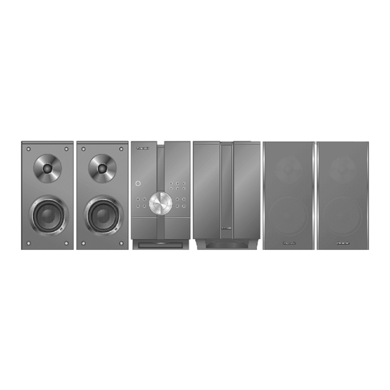
DVD Stereo System
SA-NC9GC
SA-NC9GS
SA-NC9GCS
SA-NC9GN
Colour
(K)... Black Type
Preset stations
Frequency Modulation (FM)
Frequency range
Sensitivity
S/N 26 dB
Antenna terminals
Amplitude Modulation (AM)
Frequency range
For GC, GS & GCS only
For GN only
AM sensitivity S/N 20 dB at 999 kHz
Phone jack
Terminal
Mic jack (For GC, GS & GCS only)
Sensitivity
Terminal
Music Port jack (Front)
Sensitivity
Terminal
USB jack
© 2007 Matsushita Electric Industrial Co. Ltd.. All
rights
reserved.
distribution is a violation of law.
ORDER NO. MD0703039CE
FM 30 stations
AM 30 stations
87.50 MHz to 108.00 MHz (50-kHz
4.0 µV (IHF)
2.2 µV
75 Ω (unbalanced)
522 kHz to 1629 kHz (9-kHz step)
520 kHz to 1630 kHz (10-kHz
522 kHz to 1629 kHz (9-kHz step)
1000 µV/m
Stereo, 3.5-mm jack
0.7 mV, 600 Ω
Mono, 6.3-mm jack (2 system)
100-mV, 10 kΩ
Stereo, 3.5-mm jack
Unauthorized
copying
step)
step)
and
Advertisement
Table of Contents

Related Manuals for Panasonic SA-NC9GC


Summary of Contents for Panasonic SA-NC9GC
-
Page 1: Specifications
ORDER NO. MD0703039CE DVD Stereo System SA-NC9GC SA-NC9GS SA-NC9GCS SA-NC9GN Colour (K)... Black Type Notes: This model’s DVD mechanism changer unit is DL2SV. Specifications n AMPLIFIER SECTION Preset stations FM 30 stations RMS Output Power: Dolby Digital Mode AM 30 stations 95 W per channel (3 Ω), 1 kHz,... - Page 2 (Sub sampling is 4:0:0, 4:2:0, 4:2:2 or 4:4:4). Extremely long and narrow pictures may not be displayed. MPEG-1 Layer 3, MPEG-2 Layer 3 MPEG4 data recorded with the Panasonic SD multi cameras or DVD video recorders. Conforming to SD VIDEO specifications (ASF standard) / MPEG4 (Simple Profile) video system / G.726 audio system...
- Page 3 SA-NC9GC / SA-NC9GS / SA-NC9GCS / SA-NC9GN Notes: 1. Specifications are subject to change without notice. Mass and dimensions are approximate. 2. Total harmonic distortion is measured by the digital spectrum analyzer. For information on speaker system, please refer to the original Service Manual (Order No.
-
Page 4: Table Of Contents
SA-NC9GC / SA-NC9GS / SA-NC9GCS / SA-NC9GN CONTENTS Page Page 1 Safety Precautions 10.11. Disassembly of Panel P.C.B. 1.1. General Guidelines 10.12. Disassembly of Sub Panel P.C.B. 1.2. Safety Precaution for AC Power Supply Cord (For GS 10.13. Disassembly of Deck Mechanism Unit only) 10.14. - Page 5 SA-NC9GC / SA-NC9GS / SA-NC9GCS / SA-NC9GN 18 Schematic Diagram 19.4. (E) Power P.C.B., (F) Speaker P.C.B., (G) Transformer 18.1. (A) DVD Module (DV5.0) Circuit P.C.B. & (H) Sub Heat Sink P.C.B. 18.2. (A) DVD Module (HDMI) Circuit 19.5. (I) Deck P.C.B. , (J) Deck Mechanism P.C.B., (K) Relay 18.3.
-
Page 6: Safety Precautions
SA-NC9GC / SA-NC9GS / SA-NC9GCS / SA-NC9GN 1 Safety Precautions 1.1. General Guidelines 1. When servicing, observe the original lead dress. If a short circuit is found, replace all parts which have been overheated or damaged by the short circuit. -
Page 7: Safety Precaution For Ac Power Supply Cord (For Gs Only)
SA-NC9GC / SA-NC9GS / SA-NC9GCS / SA-NC9GN 1.2. Safety Precaution for AC Power Supply Cord (For GS only) 1.3. Before Use (For GS/GCS only) Be sure to disconnect the mains cord before adjusting the voltage selector. Use a minus(-) screwdriver to set the voltage selector (on the rear panel) to the voltage setting for the area in which the unit will be used. -
Page 8: Safety Parts Information
SA-NC9GC / SA-NC9GS / SA-NC9GCS / SA-NC9GN Note : When the protection circuitry functions, the unit will not operate unless the power is first turned off and then on again. 1.6. Safety Parts Information Safety Parts List: There are special components used in this equipment which are important for safety. -
Page 9: Handling Precautions For Traverse Unit
SA-NC9GC / SA-NC9GS / SA-NC9GCS / SA-NC9GN 2 Handling Precautions for Traverse Unit The laser diode used inside optical pickup could be destroyed due to static electricity as a potential difference is caused by electrostatic load discharged from clothes or human body. Handling the parts carefully to avoid electrostatic destruction during repair. - Page 10 SA-NC9GC / SA-NC9GS / SA-NC9GCS / SA-NC9GN Fig. 3.2...
-
Page 11: Precaution Of Laser Diode
SA-NC9GC / SA-NC9GS / SA-NC9GCS / SA-NC9GN 3 Precaution of Laser Diode Caution : This product utilizes a laser diode with the unit turned "ON", invisible laser radiation is emitted from the pick up lens. Wavelength : 785 nm(CD)/662 nm(DVD) Maximum output radiation power from pick up : 100 µW/VDE... -
Page 12: About Lead Free Solder (Pbf)
SA-NC9GC / SA-NC9GS / SA-NC9GCS / SA-NC9GN 4 About Lead Free Solder (PbF) 4.1. Service caution based on legal restrictions 4.1.1. General description about Lead Free Solder (PbF) The lead free solder has been used in the mounting process of all electrical components on the printed circuit boards used for this equipment in considering the globally environmental conservation. -
Page 13: Accessories
SA-NC9GC / SA-NC9GS / SA-NC9GCS / SA-NC9GN 5 Accessories Remote control AC power supply cord (For GC/GCS only) AC power supply cord (For GS only) AC power supply cord (For GN only) FM indoor antenna AM loop antenna Video cable... - Page 14 SA-NC9GC / SA-NC9GS / SA-NC9GCS / SA-NC9GN Speaker cable sticker Metal brackets (x Short screws (x Long screws (x Lock covers (x 6) Base stands (x Allen Key...
-
Page 15: Operation Procedures
SA-NC9GC / SA-NC9GS / SA-NC9GCS / SA-NC9GN 6 Operation Procedures... -
Page 16: Main Unit Key Buttons Operations
SA-NC9GC / SA-NC9GS / SA-NC9GCS / SA-NC9GN 6.1. Main Unit Key Buttons Operations... -
Page 17: Remote Control Key Buttons Operations
SA-NC9GC / SA-NC9GS / SA-NC9GCS / SA-NC9GN 6.2. Remote Control Key Buttons Operations... -
Page 18: Disc Information
SA-NC9GC / SA-NC9GS / SA-NC9GCS / SA-NC9GN 6.3. Disc Information 6.3.1. Disc Playability... - Page 19 SA-NC9GC / SA-NC9GS / SA-NC9GCS / SA-NC9GN 6.3.2. To Play MP3/ WMA and still Pictures (JPEG)
-
Page 20: Divx Vod Content
SA-NC9GC / SA-NC9GS / SA-NC9GCS / SA-NC9GN 6.4. DivX VOD Content... -
Page 21: New Features
SA-NC9GC / SA-NC9GS / SA-NC9GCS / SA-NC9GN 7 New Features... -
Page 22: Using The Viera Link 滴 Davi Control 剩
SA-NC9GC / SA-NC9GS / SA-NC9GCS / SA-NC9GN 7.1. Using the VIERA Link “HDAVI Control™”... -
Page 23: About Highmat
SA-NC9GC / SA-NC9GS / SA-NC9GCS / SA-NC9GN 8 About HighMAT 8.1. What’s HighMAT? Consumers worldwide are using PCs to create their own collections of music, photos and even video by burning them onto CDs. But how these collections can be experienced across different devices can be confusing to navigate, time consuming to access for a DVD player, and be incomplete in terms of music information available to the customer. -
Page 24: Benefits Of Highmat
SA-NC9GC / SA-NC9GS / SA-NC9GCS / SA-NC9GN A Solution Created: HighMAT delivers a better digital media access experience by creating a standard approach for PCs to structure digital media on various physical formats and for playback devices to read the data. - Page 25 SA-NC9GC / SA-NC9GS / SA-NC9GCS / SA-NC9GN...
- Page 26 SA-NC9GC / SA-NC9GS / SA-NC9GCS / SA-NC9GN HighMAT is now available for CD Burning and in Leading DVD PlayersHighMAT is a new technology that is now available in leading software and consumer electronic devices to dramatically improve the digital media experience when you create homemade CDsHighMAT delivers a simple, standardized way for PC software and consumer electronics devices to talk to each other and work better together.
-
Page 27: Self Diagnosis And Special Mode Setting
SA-NC9GC / SA-NC9GS / SA-NC9GCS / SA-NC9GN 9 Self diagnosis and special mode setting This unit is equipped with functions for checking and inspecting namely: Self-Diagnostic and Test Mode. 9.1. Service Mode Summary Table The service modes can be activated by pressing various button combination on the player and remote control unit. -
Page 28: Service Mode Table
SA-NC9GC / SA-NC9GS / SA-NC9GCS / SA-NC9GN 9.2.1. Service Mode Table 1 Item FL Display Key Operation Mode Name Description Front Key Jitter check Jitter check. (Display 1) In STOP (no disc) mode, press Jitter rate is measured and displayed. - Page 29 SA-NC9GC / SA-NC9GS / SA-NC9GCS / SA-NC9GN Item FL Display Key Operation Mode Name Description Front Key Initial setting of Initial setting of laser drive current. 1. (Display 1) In STOP (no disc) mode, press laser drive current Initial current value for the DVD laser...
- Page 30 SA-NC9GC / SA-NC9GS / SA-NC9GCS / SA-NC9GN Item FL Display Key Operation Mode Name Description Front Key CD laser drive CD laser drive current measurement. (Display 1) In STOP (no disc) mode, press current CD laser drive current is measured...
- Page 31 SA-NC9GC / SA-NC9GS / SA-NC9GCS / SA-NC9GN 9.2.3. Service Mode Table 3 Item FL Display Key Operation Mode Name Description Front Key Micro-processor Micro-processor firmware version (Display 1) In STOP (no disc) mode, press firmware version display & EEPROM checksum ] button on the main unit, display &...
- Page 32 SA-NC9GC / SA-NC9GS / SA-NC9GCS / SA-NC9GN Item FL Display Key Operation Mode Name Description Front Key Region display Region code display, TV Broadcasting In STOP (no disc) mode, press system & the model no. information ] button on the main unit,...
- Page 33 SA-NC9GC / SA-NC9GS / SA-NC9GCS / SA-NC9GN 9.2.4. Service Mode Table 4 Item FL Display Key Operation Mode Name Description Front Key DVD (HDMI) module DVD (HDMI) module firmware version In STOP (no disc) mode, press firmware version is displayed on the FL Display.
- Page 34 SA-NC9GC / SA-NC9GS / SA-NC9GCS / SA-NC9GN 9.2.5. Service Mode Table 5 Item FL Display Key Operation Mode Name Description Front Key Timer 1 check Timer 1 check. (Display 1) STOP disc) mode, press Laser operation time is measured ] button on the main unit, and separately for DVD laser and CD ] button on the remote control unit.
-
Page 35: Dvd Self Diagnostic Function - Error Code
SA-NC9GC / SA-NC9GS / SA-NC9GCS / SA-NC9GN 9.3. DVD Self Diagnostic Function - Error Code 9.3.1. Mechanism Error Code Table Error Code Diagnosis Contents Description of error Automatic FL Display Remarks Tray loading error The tray opening and Press [... - Page 36 SA-NC9GC / SA-NC9GS / SA-NC9GCS / SA-NC9GN Error Code Diagnosis Contents Description of error Automatic FL Display Remarks Traverse servo error The traverse Press [ ] on main unit for abnormal. (Traverse next error. servo, DV 5.0 LSI IC (IC8001), motor error.)
- Page 37 SA-NC9GC / SA-NC9GS / SA-NC9GCS / SA-NC9GN Error Code Diagnosis Contents Description of error Automatic FL Display Remarks U703 HDMI/DVI attestation When attestation Press [ ] on main unit for error (HDCP) with the TV side next error. fails when connecting it...
-
Page 38: Doctor Mode
SA-NC9GC / SA-NC9GS / SA-NC9GCS / SA-NC9GN 9.3.3. ECC Error Code Table Error Code Diagnosis Contents Description of error Automatic FL Display Remarks F600 Administrative become impossible Press [ ] on main unit for information cannot be NaviPack etc. were next error. - Page 39 SA-NC9GC / SA-NC9GS / SA-NC9GCS / SA-NC9GN Item FL Display Key Operation Mode Name Description Front Key To enter into To enter into doctor mode for (Display 1) Using special remote control doctor mode checking for various items and [1DDF] or [1CDF] is received during displaying checksum and software power on.
- Page 40 SA-NC9GC / SA-NC9GS / SA-NC9GCS / SA-NC9GN Item FL Display Key Operation Mode Name Description Front Key Volume setting To forced volume setting. In Doctor Mode. [0100] is received during power on. In Doctor Mode. [0113] is received during power on.
- Page 41 SA-NC9GC / SA-NC9GS / SA-NC9GCS / SA-NC9GN Item FL Display Key Operation Mode Name Description Front Key All FL display To check the FL segments display (all In Doctor Mode. segments of both FL will be light up). [1144] is received during power on.
- Page 42 SA-NC9GC / SA-NC9GS / SA-NC9GCS / SA-NC9GN Item FL Display Key Operation Mode Name Description Front Key LDO & LDD Laser current initial measurement and (Display 1) In Doctor Mode. DVD laser current measurement. [1141] is received during power on.
- Page 43 SA-NC9GC / SA-NC9GS / SA-NC9GCS / SA-NC9GN Item FL Display Key Operation Mode Name Description Front Key Jitter check Jitter check. (Display 1) In Doctor Mode. Jitter rate is measured and displayed. [1142] is received during power on. Measurement is repeatedly done in the cycle of one second.
- Page 44 SA-NC9GC / SA-NC9GS / SA-NC9GCS / SA-NC9GN 9.4.1. Service Mode Table 2 Item FL Display Key Operation Mode Name Description Front Key ADSC internal ADSC internal RAM data check. In STOP (no disc) mode, press RAM data check ADSC internal RAM data is read out ] button on the main unit, and displayed.
- Page 45 SA-NC9GC / SA-NC9GS / SA-NC9GCS / SA-NC9GN Item FL Display Key Operation Mode Name Description Front Key Micro-processor Micro-processor firmware version (Display 1) In STOP (no disc) mode, press firmware version display & EEPROM checksum ] button on the main unit, display &...
- Page 46 SA-NC9GC / SA-NC9GS / SA-NC9GCS / SA-NC9GN Item FL Display Key Operation Mode Name Description Front Key DVD (HDMI) module DVD (HDMI) module firmware version In STOP (no disc) mode, press firmware version is displayed on the FL Display. ] button on the main unit,...
- Page 47 SA-NC9GC / SA-NC9GS / SA-NC9GCS / SA-NC9GN Model Series Country Region Region TV Broadcasting Product Code System Signal System Region Display OSD Menu Language (Default) (Default) PL, GCP, LB Central/South/Latin NTSC NTSC (*D) English, Spanish, French, America Brazilian Portuguese SECAM...
- Page 48 SA-NC9GC / SA-NC9GS / SA-NC9GCS / SA-NC9GN Item FL Display Key Operation Mode Name Description Front Key Timer 1 check Timer 1 check. (Display 1) STOP disc) mode, press Laser operation time is measured ] button on the main unit, and separately for DVD laser and CD ] button on the remote control unit.
-
Page 49: Sales Demonstration Lock Function
SA-NC9GC / SA-NC9GS / SA-NC9GCS / SA-NC9GN 9.5. Sales Demonstration Lock Function This function prevents discs from being lost when the unit is used for sales demonstrations by disabling the disc eject function. “LOCKED” is displayed on the unit, and ordinary operation is disabled. -
Page 50: Assembling And Disassembling
SA-NC9GC / SA-NC9GS / SA-NC9GCS / SA-NC9GN 10 Assembling and Disassembling 10.1. Caution “ATTENTION SERVICER” Some chassis components may have sharp edges. Be careful when disassembling and servicing. 1. This section describes procedures for checking the operation of the major printed circuit boards and replacing the main components. - Page 51 SA-NC9GC / SA-NC9GS / SA-NC9GCS / SA-NC9GN...
-
Page 52: Disassembly Flow Chart
SA-NC9GC / SA-NC9GS / SA-NC9GCS / SA-NC9GN 10.2. Disassembly flow chart The following chart is the procedure for disassembling the casing and inside parts for internal inspection when carrying out the servicing. To assemble the unit, reverse the steps shown in the chart as below. -
Page 53: Main Parts Location
SA-NC9GC / SA-NC9GS / SA-NC9GCS / SA-NC9GN 10.3. Main Parts Location... -
Page 54: Disassembly Of Top Cabinet
SA-NC9GC / SA-NC9GS / SA-NC9GCS / SA-NC9GN 10.4. Disassembly of Top Cabinet Step 1 Remove 4 screws at each side. Step 3 Lift up both sides of the top cabinet. Step 2 Remove 7 screws at rear panel. Step 4 Push the top cabinet backwards to release the catches. -
Page 55: Disassembly Of Dvd Changer Unit (Dl2Sv) & Hdmi
SA-NC9GC / SA-NC9GS / SA-NC9GCS / SA-NC9GN (Q5111/Q5101/Q5102). Step 9 Remove 1 screw. Step 8 Remove 2 screws. Step 10 Remove transistor clip. Step 11 Desolder & remove the component. · Replacement regulator transistors 10.6. Disassembly of DVD Changer Unit (DL2SV) & HDMI P.C.B. -
Page 56: Disassembly Of Main P.c.b
SA-NC9GC / SA-NC9GS / SA-NC9GCS / SA-NC9GN Step 7 Flip the HDMI P.C.B. over. Step 8 Detach FFC cables at connectors (FP8531, FP8251, & FP8101). Step 9 Remove HDMI P.C.B.. 10.7. Disassembly of Main P.C.B. · Follow the (Step 1) - (Step 5) of Item 10.4 ·... -
Page 57: Disassembly Of Power P.c.b. & Speaker P.c.b
SA-NC9GC / SA-NC9GS / SA-NC9GCS / SA-NC9GN Step 4 Release 2 claws. Step 3 Bent the front panel unit slightly forward as shown. Step 5 Remove the front panel. Note: Ensure 2 claws located at the bottom chassis is seated into the 2 slots at bottom of front panel at 2 catches (one on each side) of bottom chassis to be aligned to front panel’s slot. -
Page 58: Replacement For Power Amp Ic
SA-NC9GC / SA-NC9GS / SA-NC9GCS / SA-NC9GN Speaker P.C.B.. Step 3 Remove 3 screws on Power P.C.B. and 1 screw on 10.10. Replacement for Power Amp IC · Follow the (Step 1) - (Step 5) of Item 10.4 · Follow the (Step 1) - (Step 3) of Item 10.5 ·... -
Page 59: Disassembly Of Panel P.c.b
SA-NC9GC / SA-NC9GS / SA-NC9GCS / SA-NC9GN 10.11. Disassembly of Panel P.C.B. · Follow the (Step 1) - (Step 5) of Item 10.4 · Follow the (Step 1) - (Step 3) of Item 10.6 · Follow the (Step 1) - (Step 5) of Item 10.8 Step 1 Remove DVD changer unit. -
Page 60: Disassembly Of Deck Mechanism Unit
SA-NC9GC / SA-NC9GS / SA-NC9GCS / SA-NC9GN Step 4 Release catch and remove Sub Panel P.C.B.. 10.13. Disassembly of Deck Mechanism Unit · Follow the (Step 1) - (Step 5) of Item 10.4 · Follow the (Step 1) - (Step 3) of Item 10.6 ·... - Page 61 SA-NC9GC / SA-NC9GS / SA-NC9GCS / SA-NC9GN Step 2 Raise the CD Loading unit vertically. Step 3 Slide the lever fully in the direction of arrow, pull the tray out. (The sub tray and tray be out together). Note: Step 7 Release the vertically lock lever, free the sensor lever.
- Page 62 SA-NC9GC / SA-NC9GS / SA-NC9GCS / SA-NC9GN Step 3 Hook the drive arm hanging area over the tray slider Step 4 Push the tray. and tray. Step 5 Make sure that the tray and the drive arm move smoothly. 10.15.2. Disassembly of CD Loading Section Step 1 Spead the tabs at the both sides and push out the drive Step 4 Release the 2 tabs and remove the guide piece (R).
-
Page 63: Disassembly Of Deck Mechanism Main Components
SA-NC9GC / SA-NC9GS / SA-NC9GCS / SA-NC9GN Step 8 Unlock the tab and remove the lock lever. Step 14 Remove the change lever. Step 9 Remove the belt. Step 15 Remove the drive rack, the sub rack and drive gear. - Page 64 SA-NC9GC / SA-NC9GS / SA-NC9GCS / SA-NC9GN 10.16.1. Disassembly of Motor, Capstan Belt A, Capstan Belt B, and Winding Belt (Deck Mechanism Unit)
-
Page 65: Disassembly Of Deck Mechanism P.c.b
SA-NC9GC / SA-NC9GS / SA-NC9GCS / SA-NC9GN 10.17. Disassembly of Deck Mechanism P.C.B. 10.18. Disassembly of cassette lid · Follow the (Step 1) - (Step 5) of Item 10.4 · Follow the (Step 1) - (Step 3) of Item 10.6 ·... -
Page 66: Rectification For Tape Jam Problem
SA-NC9GC / SA-NC9GS / SA-NC9GCS / SA-NC9GN Step 2 Remove spring and push the cassette lid in the direction of arrows. 10.19. Rectification for tape jam problem · Follow the (Step 1) - (Step 5) of Item 10.4 Step 1 If a cassette tape cannot be removed from the deck (the Step 2 Push the lever upward and open the cassette lid. - Page 67 SA-NC9GC / SA-NC9GS / SA-NC9GCS / SA-NC9GN Step 2 Push and click the lock cover unit to the fastened mecha bracket ass’y. Note: If you play 5.1 Channel sources in this stack up assembly, use Bi-Amp TS Mode or Party-Stereo mode to enjoy better sound...
-
Page 68: Service Positions
SA-NC9GC / SA-NC9GS / SA-NC9GCS / SA-NC9GN 11 Service Positions Note: For description of the disassembly procedures, see the Section 10. 11.1. Checking and Repairing of Main P.C.B. & DVD Module P.C.B. -
Page 69: Checking And Repairing Of Hdmi P.c.b
SA-NC9GC / SA-NC9GS / SA-NC9GCS / SA-NC9GN 11.2. Checking and Repairing of HDMI P.C.B. -
Page 70: Checking And Repairing Of Deck & Deck Mechanism
SA-NC9GC / SA-NC9GS / SA-NC9GCS / SA-NC9GN 11.3. Checking and Repairing of Deck & Deck Mechanism P.C.B. -
Page 71: Checking And Repairing Of Power & Speaker P.c.b
SA-NC9GC / SA-NC9GS / SA-NC9GCS / SA-NC9GN 11.4. Checking and Repairing of Power & Speaker P.C.B. -
Page 72: Checking And Repairing Of Panel P.c.b
SA-NC9GC / SA-NC9GS / SA-NC9GCS / SA-NC9GN 11.5. Checking and Repairing of Panel P.C.B. -
Page 73: Procedure For Checking Operation Of Individual Parts Of Deck Mechanism Unit
SA-NC9GC / SA-NC9GS / SA-NC9GCS / SA-NC9GN 12 Procedure for Checking Operation of Individual Parts of Deck Mechanism Unit 12.1. Operation Check with Cassette Tape 1. Pull up the EJECT lever using a rubber band. (Fig. 6) 2. Supply DC5V to MOTOR. (→ MOTOR rotates.) (Fig. 5) 3. - Page 74 SA-NC9GC / SA-NC9GS / SA-NC9GCS / SA-NC9GN Fig. 7...
-
Page 75: Measurement And Adjustments
SA-NC9GC / SA-NC9GS / SA-NC9GCS / SA-NC9GN 13 Measurement And Adjustments 13.1. Cassette Deck Section 13.1.1. Requirements · Test tape (QZZCFM) (QZZCWAT) · Normal blank cassette tape (QZZCRA) · Digital frequency counter · Oscilloscope · Electrical voltmeter · Headphone jack output jig (Fig 8) 13.1.2. - Page 76 SA-NC9GC / SA-NC9GS / SA-NC9GCS / SA-NC9GN Fig. 10 Fig. 11 13.1.5. Bias Voltage Check 1. Connect an electrical voltmeter. (Fig 12) (Fig 9 for location of test points) 2. Set the function to “TAPE” position. 3. Insert a normal blank cassette tape (QZZCRA).
-
Page 77: Voltage And Waveform Chart
SA-NC9GC / SA-NC9GS / SA-NC9GCS / SA-NC9GN 14 Voltage and Waveform Chart Note: Circuit voltage and waveform described herein shall be regarded as reference information when probing defect point, because it may differ from an actual measuring value due to difference of Measuring instrument and its measuring condition and product itself. - Page 78 SA-NC9GC / SA-NC9GS / SA-NC9GCS / SA-NC9GN...
-
Page 79: Main P.c.b
SA-NC9GC / SA-NC9GS / SA-NC9GCS / SA-NC9GN 14.2. Main P.C.B. - Page 80 SA-NC9GC / SA-NC9GS / SA-NC9GCS / SA-NC9GN...
-
Page 81: Panel P.c.b
SA-NC9GC / SA-NC9GS / SA-NC9GCS / SA-NC9GN 14.3. Panel P.C.B. -
Page 82: Power P.c.b
SA-NC9GC / SA-NC9GS / SA-NC9GCS / SA-NC9GN 14.4. Power P.C.B. 14.5. Sub Heat Sink P.C.B. 14.6. Sub Panel P.C.B. -
Page 83: Transformer P.c.b
SA-NC9GC / SA-NC9GS / SA-NC9GCS / SA-NC9GN 14.7. Transformer P.C.B. 14.8. Tray Loading P.C.B. 14.9. Deck P.C.B. & Deck Mechanism P.C.B. -
Page 84: Waveform Chart
SA-NC9GC / SA-NC9GS / SA-NC9GCS / SA-NC9GN 14.10. Waveform Chart... - Page 85 SA-NC9GC / SA-NC9GS / SA-NC9GCS / SA-NC9GN...
- Page 86 SA-NC9GC / SA-NC9GS / SA-NC9GCS / SA-NC9GN...
-
Page 87: Wiring Connection Diagram
SA-NC9GC / SA-NC9GS / SA-NC9GCS / SA-NC9GN 15 Wiring Connection Diagram TRAY LOADING P.C.B. SOLDER SIDE SUB PANEL P.C.B. SOLDER SIDE CS901 JK6901 DECK MECHANISM P.C.B. MIC 2 SOLDER SIDE SOLENOID MIC 1 CS971 9 ..1 JK6902 1. - Page 88 SA-NC9GC / SA-NC9GS / SA-NC9GCS / SA-NC9GN...
-
Page 89: Block Diagram
SA-NC9GC / SA-NC9GS / SA-NC9GCS / SA-NC9GN 16 Block Diagram 16.1. DVD IC8001 IC8251 MN2DS0018VP C0GBG0000048 OPTICAL PICK UP UNIT DV5.0 LSI MOTOR DRIVER FP8531 TA(DVD) CH1,2 VIN1 MUTE FP8531 TB(DVD) VIN2 MUTE FP8531 TC(DVD) VIN3 MUTE FP8531 TD(DVD) VIN4... - Page 90 SA-NC9GC / SA-NC9GS / SA-NC9GCS / SA-NC9GN IC8421 IC8001 MN2DS0018VP C0FBBK000050 OPTICAL PIC-UP UNIT DV5.0 LSI AUDIO DAC FP8531 FP8101 CN2036 OUTPUT AMP AND V OUT1 DVD MIX L RFINN SRCK LOW-PASS FILTER LRCK LRCK FP8531 DATA2 OUTPUT AMP AND...
- Page 91 SA-NC9GC / SA-NC9GS / SA-NC9GCS / SA-NC9GN IC8001 MN2DS0018VP DV5.0 LSI Q8331 FP8101 CN2036 Y/PY/G DAC1 OUT BUFFER Q8335 FP8101 CN2036 CB/PB/B DAC2 OUT BUFFER Q8341 FP8101 CN2036 CR/PR/R BUFFER DAC3 OUT MAIN (2/3) Q8321 FP8101 CN2036 DAC4 OUT BUFFER...
-
Page 92: Main
SA-NC9GC / SA-NC9GS / SA-NC9GCS / SA-NC9GN 16.2. Main Q2022(Q2021) Q2205 MUTE MUTE VD MUTE SWITCH SWITCH IC2101 C1AB00002735 AUDIO SIGNAL PROCESSOR Q2852 SWITCH CEC-in TO DVD MODULE (3/3) CEC-OUT SUBIN Q2853 CLOCK IC2103(1/4) SWITCH C0ABCB000088 IC2103(2/4) OP-AMP C0ABCB000088 IC2103(3/4) - Page 93 SA-NC9GC / SA-NC9GS / SA-NC9GCS / SA-NC9GN IC2401 C9ZB00000461 VIDEO BUFFER CYIN CBOUT JK2401 CROUT CBIN CR/CB +15V FROM CRIN DVD MODULE (3/3) Q2707,Q2709 REGULATOR JK2401 YOUT COMPOSITE/Y SYS6V VOUT M+18V COUT IC2741 C0DAAMH00012 S-VIDEO REGULATOR IC A+5V Q2414 D2413...
- Page 94 SA-NC9GC / SA-NC9GS / SA-NC9GCS / SA-NC9GN IC2600 C2CBYY000451 MICROPROCESSOR Q2041 FROM POWER SWITCH DVD_MUTE MUTE-F_HOP MPORT_SW FROM FROM DVD-CLK HP_SW DVD MODULE SUB PANEL DVD-CMD KEY3 DVD-STA Q2802 Q2803 SWITCH SWITCH VREF DRIVER TUNER-DOUT TUNER-CLK TUNER PACK TUNER-DIN SYNC...
-
Page 95: Panel/Sub Panel/Usb Relay
SA-NC9GC / SA-NC9GS / SA-NC9GCS / SA-NC9GN 16.3. Panel/Sub Panel/USB Relay F1 1 F1 1 D6501 FL6201 FL6101 A2BD00000173 F2 35 F2 35 A2BC00000072 RIGHT FL LEFT FL Q6881 Q6551 Q35 30 TO TRANSFORMER DRIVER DRIVER D6503 19-30 6-12 Q6702... -
Page 96: Power
SA-NC9GC / SA-NC9GS / SA-NC9GCS / SA-NC9GN 16.4. Power SPEAKER CIRCUIT JK5101 IC5400 SPEAKER C1AA00000755 2CH DIGITAL AMP L5470 L5472 OUT2 14 IN1+ SPEAKER TO MAIN (1/3) OUT1 10 IN2- L5471 SPEAKER 4,8,16,20 OSC TRANSFORMER 6,11,13,18 MODE MODE 23 1 OSC... -
Page 97: Transformer
SA-NC9GC / SA-NC9GS / SA-NC9GCS / SA-NC9GN 16.5. Transformer SUB HEAT SINK CIRCUIT Q5901, Q5110 D5950-D5953, T5950 D5970-D5973 (NC9 ONLY) +30V Q5111 +15V SUPPLY TO POWER Q5902, Q5108, S5950 Q5109 Q5903, VOLTAGE Q5904 (GCS/GS Only) -30V SELECTOR DC DETECT SWITCH SUB HEAT SINK P.C.B... -
Page 98: Deck/Deck Mechanism/Tray Loading
SA-NC9GC / SA-NC9GS / SA-NC9GCS / SA-NC9GN 16.6. Deck/Deck Mechanism/Tray Loading IC1001 AN7326K DECK R/P IC (DECK 1) .B. HEAD Q1101, Q1103, Q1201 Q1203 SWITCH SWITCH (DECK 2) Q1302 HEAD MUTE SWITCH TO MAIN DRIVER (3/3) L1301 Q1309,Q1310 Q1304 Q1303... -
Page 99: Notes Of Schematic Diagrams
SA-NC9GC / SA-NC9GS / SA-NC9GCS / SA-NC9GN 17 Notes of Schematic Diagrams · Voltage and Signal lines: (All schematic diagrams may be modified at any time with the development of the new technology) : +B Signal line S901 : OPEN Switch... - Page 100 SA-NC9GC / SA-NC9GS / SA-NC9GCS / SA-NC9GN...
-
Page 101: Schematic Diagram
SA-NC9GC / SA-NC9GS / SA-NC9GCS / SA-NC9GN 18 Schematic Diagram 18.1. (A) DVD Module (DV5.0) Circuit SCHEMATIC DIAGRAM - 1 DVD MODULE (DV5) CIRCUIT : CD HEAD SIGNAL LINE : DVD RF SIGNAL LINE : DVD AUDIO SIGNAL LINE : +B SIGNAL LINE... - Page 102 SA-NC9GC / SA-NC9GS / SA-NC9GCS / SA-NC9GN SCHEMATIC DIAGRAM - 2 DVD MODULE (DV5) CIRCUIT : +B SIGNAL LINE : DVD AUDIO SIGNAL LINE : DVD VIDEO SIGNAL LINE : MAIN SIGNAL LINE : USB SIGNAL LINE ADAC-CLK D2: DVD MODULE (DV5): SCHEMATIC DIAGRAM 1-4...
- Page 103 SA-NC9GC / SA-NC9GS / SA-NC9GCS / SA-NC9GN SCHEMATIC DIAGRAM - 3 DVD MODULE (DV5) CIRCUIT : +B SIGNAL LINE : DVD HEAD SIGNAL LINE : MOTOR DRIVE SIGNAL LINE : DVD RF SIGNAL LINE : DVD AUDIO SIGNAL LINE TO DVD MODULE (DV5)
- Page 104 SA-NC9GC / SA-NC9GS / SA-NC9GCS / SA-NC9GN SCHEMATIC DIAGRAM - 4 DVD MODULE (DV5) CIRCUIT : CD HEAD SIGNAL LINE : MOTOR DRIVE SIGNAL LINE : +B SIGNAL LINE : DVD HEAD SIGNAL LINE : TRACKING ERROR SIGNAL LINE : FOCUS ERROR SIGNAL LINE...
-
Page 105: A) Dvd Module (Hdmi) Circuit
SA-NC9GC / SA-NC9GS / SA-NC9GCS / SA-NC9GN 18.2. (A) DVD Module (HDMI) Circuit SCHEMATIC DIAGRAM - 5 DVD MODULE(HDMI) CIRCUIT : +B SIGNAL LINE : DVD AUDIO SIGNAL LINE : DVD VIDEO SIGNAL LINE : MAIN SIGNAL LINE LB3907 J0JHC0000045... -
Page 106: B) Main Circuit
SA-NC9GC / SA-NC9GS / SA-NC9GCS / SA-NC9GN 18.3. (B) Main Circuit SCHEMATIC DIAGRAM - 6 MAIN CIRCUIT : +B SIGNAL LINE : -B SIGNAL LINE : DVD VIDEO SIGNAL LINE : MAIN SIGNAL LINE : AM/FM SIGNAL LINE : AUX SIGNAL LINE... - Page 107 SA-NC9GC / SA-NC9GS / SA-NC9GCS / SA-NC9GN SCHEMATIC DIAGRAM - 7 MAIN CIRCUIT : +B SIGNAL LINE : -B SIGNAL LINE : MAIN SIGNAL LINE Q2631 HBASS_SW B1ABCF000176 LOW PASS FILTER Q2631 C2727 0.01 R2631 R2630 R2601 C2601 R2602 50V10...
- Page 108 SA-NC9GC / SA-NC9GS / SA-NC9GCS / SA-NC9GN SCHEMATIC DIAGRAM - 8 MAIN CIRCUIT : -B SIGNAL LINE : TAPE PLAYBACK SIGNAL LINE : +B SIGNAL LINE : DVD VIDEO SIGNAL LINE : MAIN SIGNAL LINE : TAPE RECORD SIGNAL LINE...
- Page 109 SA-NC9GC / SA-NC9GS / SA-NC9GCS / SA-NC9GN SCHEMATIC DIAGRAM - 9 MAIN CIRCUIT : -B SIGNAL LINE : +B SIGNAL LINE : DVD VIDEO SIGNAL LINE : MAIN SIGNAL LINE IC2660 E-EPROM IC (NOT SUPPLIED) EP_CS VREF C2980 MAIN SECTION (2/4)
-
Page 110: C) Panel Circuit
SA-NC9GC / SA-NC9GS / SA-NC9GCS / SA-NC9GN 18.4. (C) Panel Circuit SCHEMATIC DIAGRAM - 10 PANEL CIRCUIT :+B SIGNAL LINE C6701 50V22 C6716 50V22 FL6101 A2BC00000072 TRANSFORMER W6081 FL6201 CIRCUIT(CN5951) LEFT FL IN SCHEMATIC A2BD00000173 R6742 Q6881 FL-GND DIAGRAM - 15... -
Page 111: D) Sub Panel Circuit
SA-NC9GC / SA-NC9GS / SA-NC9GCS / SA-NC9GN 18.5. (D) Sub Panel Circuit SCHEMATIC DIAGRAM - 11 SUB PANEL CIRCUIT : MAIN SIGNAL LINE : USB SIGNAL LINE :+B SIGNAL LINE LB9001 C9002 J0JHC0000034 0.01 CN9002 DGND VBUS DVD MODULE DGND... -
Page 112: E) Power Circuit
SA-NC9GC / SA-NC9GS / SA-NC9GCS / SA-NC9GN 18.6. (E) Power Circuit SCHEMATIC DIAGRAM - 12 POWER CIRCUIT :+B SIGNAL LINE : -B SIGNAL LINE : MAIN SIGNAL LINE L5501 J0JKB0000020 VDDP IC5400 C5515 C5518 100n C5512 100n C1AA00000755 35V1000 TRANSFORMER... - Page 113 SA-NC9GC / SA-NC9GS / SA-NC9GCS / SA-NC9GN SCHEMATIC DIAGRAM - 13 POWER CIRCUIT :+B SIGNAL LINE : MAIN SIGNAL LINE : -B SIGNAL LINE IC5300 C1AA00000755 2-CH DIGITAL AMP R5301 C5338 C5321C5323 C5327 R5311 W5104 C5315 C5324 C5322 C5320 100n 100n...
-
Page 114: F) Speaker Circuit
SA-NC9GC / SA-NC9GS / SA-NC9GCS / SA-NC9GN 18.7. (F) Speaker Circuit SCHEMATIC DIAGRAM - 14 SPEAKER CIRCUIT :+B SIGNAL LINE :MAIN SIGNAL LINE SP_GND L5471 G0B9R5K00001 R5473 C5475 C5473 C5477 L5472 G0B9R5K00001 C5474 H5605 R5474 C5476 SURR-GND SURR-GND C5478 RIGHT... -
Page 115: G) Transformer Circuit
SA-NC9GC / SA-NC9GS / SA-NC9GCS / SA-NC9GN 18.8. (G) Transformer Circuit SCHEMATIC DIAGRAM - 15 TRANSFORMER CIRCUIT :+B SIGNAL LINE CN5101 DC_DET_1 +15v Q5903 R5985 Q5904 Q5903,Q5904 B1GBCFJJ0051 OUT +vcc PCONT SWITCH SUB HEAT SINK CIRCUIT (H5102) IN SCHEMATIC R5984... -
Page 116: H) Sub Heat Sink Circuit
SA-NC9GC / SA-NC9GS / SA-NC9GCS / SA-NC9GN 18.9. (H) Sub Heat Sink Circuit SCHEMATIC DIAGRAM - 16 SUB HEAT SINK CIRCUIT :+B SIGNAL LINE : -B SIGNAL LINE H5102 +15v OUT +vcc +30v_SMALL TRANSFORMER CIRCUIT (CN5101) R5122 IN SCHEMATIC R5121... -
Page 117: I) Deck Circuit
SA-NC9GC / SA-NC9GS / SA-NC9GCS / SA-NC9GN 18.10. (I) Deck Circuit SCHEMATIC DIAGRAM - 17 DECK CIRCUIT : TAPE RECORD SIGNAL LINE : TAPE PLAYBACK SIGNAL LINE :+B SIGNAL LINE C1105 470P C1122 0.01 R1103 AFGND PBLOUT PBLOUT CP1301 PBLIN... -
Page 118: J) Deck Mechanism Circuit, (K) Relay Circuit & (L) Tray Loading Circuit
:-B SIGNAL LINE IC904 C0GAY0000013 MOTOR DRIVER TRAY CW M+9V GND1 MAIN CIRCUIT VREF+ (CN2857) IN SCHEMATIC TRAY CCW DIAGRAM-7 S901 PLAY TRAY CLOSE S902 OPEN C984 TRAY OPEN 25V10 CS901 LOADING MOTOR SA-NC9GC/GCS/GS/GN DECK MECHANISM / RELAY / TRAY LOADING CIRCUIT... -
Page 119: Optical Pickup Unit Circuit
SA-NC9GC / SA-NC9GS / SA-NC9GCS / SA-NC9GN 18.12. Optical Pickup Unit Circuit SCHEMATIC DIAGRAM - 19 OPTICAL PICKUP UNIT CIRCUIT (FOR REFERENCE ONLY) TO ACT TO HFM GND(Im) RELAY CIRCUIT (FP8004) IN VREF2(RF-) PIN(DVD) SCHEMATIC LD(CD) DIAGRAM-18 LD GND LD(DVD) - Page 120 SA-NC9GC / SA-NC9GS / SA-NC9GCS / SA-NC9GN...
-
Page 121: Printed Circuit Board
SA-NC9GC / SA-NC9GS / SA-NC9GCS / SA-NC9GN 19 Printed Circuit Board Note: Circuit board diagrams may be modified at any time with the development of new technology. -
Page 122: A) Dvd Module P.c.b. (Side A & B )
SA-NC9GC / SA-NC9GS / SA-NC9GCS / SA-NC9GN 19.1. (A) DVD Module P.C.B. (Side A & B ) DVD MODULE P.C.B (REPX0563K...GC/GS) (REPX0563L...GCS) (REPX0563N...GN) Q3942 Q3943 R3945 FP3902 C8424 R3944 FL8104 Q3902 FP8101 R3904 Q3901 RX3901 R3925 R3943 C3927 C3920 R3946... -
Page 123: B) Main
SA-NC9GC / SA-NC9GS / SA-NC9GCS / SA-NC9GN 19.2. (B) Main P.C.B. (REPX0592...GC/GS) MAIN P.C.B (REPX0592B...GN) (REPX0592C...GCS) COMPONENT REC OUT VIDEO OUT S-VIDEO OUT VIDEO OUT C2420 JK2401 C2371 C2418 C2400 L2368 W2827 W2200 L2406 C2093 R2095 R2407 R2429 R2097C2091 C2065... -
Page 124: C) Panel P.c.b. & (D) Sub Panel
SA-NC9GC / SA-NC9GS / SA-NC9GCS / SA-NC9GN 19.3. (C) Panel P.C.B. & (D) Sub Panel P.C.B. PANEL P.C.B (REPX0593A...GC/GS/GCS) SUB PANEL P.C.B (REPX0593A...GC/GS/GCS) (REPX0593B...GN) (REPX0593B...GN) SENSOR S6102 JK6901... FL6101 GC/GS/GCS (DISPLAY/-DEMO) D6807 C6505 S6103 S6101 W6088 R6541 (RECORD) W6074 POWER... -
Page 125: E) Power P.c.b., (F) Speaker P.c.b., (G) Transformer
SA-NC9GC / SA-NC9GS / SA-NC9GCS / SA-NC9GN 19.4. (E) Power P.C.B., (F) Speaker P.C.B., (G) Transformer P.C.B. & (H) Sub Heat Sink P.C.B. POWER P.C.B (REPX0594A...GC/GN) TRANSFORMER P.C.B (REPX0594A...GC/GN) (REPX0594C...GCS/GS) (REPX0594C...GCS/GS) L5951 Q5102 Q5903 250V T2.5AL R5478 ...GC/GN C5986 K5919... -
Page 126: I) Deck P.c.b. , (J) Deck Mechanism P.c.b., (K) Relay
SA-NC9GC / SA-NC9GS / SA-NC9GCS / SA-NC9GN 19.5. (I) Deck P.C.B. , (J) Deck Mechanism P.C.B., (K) Relay P.C.B. & (L) Tray Loading P.C.B. RELAY P.C.B (REPX0604A) DECK P.C.B (REPX0594A...GC/GN) (REPX0594C...GCS/GS) W1930 Q1309 Q1310 W1909 W1935 FP8003 W1977 Q1303 C1317... -
Page 127: Basic Troubleshooting Guide
SA-NC9GC / SA-NC9GS / SA-NC9GCS / SA-NC9GN 20 Basic Troubleshooting Guide 20.1. Basic Troubleshooting Guide for Traverse Unit (DVD Module P.C.B.) Problems Checking Points Checking Components 1) Distorted picture or abnormal a) Check SDRAM address, data bus, CLK and IC8051... - Page 128 SA-NC9GC / SA-NC9GS / SA-NC9GCS / SA-NC9GN Problems Checking Points Checking Components 2) When switching the video output 1) Supply for Up-Con (IC3901). LB3902 - Pin 9 & 124 mode from 480P to 720P/1080i, TV display becomes blank. 2) GND for Up-Con.
-
Page 129: Illustration Of Ics, Transistors And Diodes
SA-NC9GC / SA-NC9GS / SA-NC9GCS / SA-NC9GN 21 Illustration of ICs, Transistors and Diodes AN7326K C0DAAMH00012 C0HBB0000057 (64P) C0ABBB000230 (8P) C0GBG0000048 C1AB00002735 (100P) C0ABCB000088 (14P) C2BBYY000451 (100P) C0JBAB000011 (14P) C2BBYY000452 (100P) C0JBAR000326(16P) MN2DS0018MP (216P) C1BB00001061 (16P) C3ABPG000145 (54P) MN864702A (128P) - Page 130 SA-NC9GC / SA-NC9GS / SA-NC9GCS / SA-NC9GN B0BC027A0209 B1DEGM000026 Cathode Anode...
-
Page 131: Terminal Function Of Ic
SA-NC9GC / SA-NC9GS / SA-NC9GCS / SA-NC9GN 22 Terminal Function of IC 22.1. IC2600 (C2CBYY000451 ) Pin No. Mark Function MOTOR Deck motor control System Microprocessor (L: OFF; H: ON) PLUNGER Deck plunger control Pin No. Mark Function (L: OFF; H: ON) - Page 132 SA-NC9GC / SA-NC9GS / SA-NC9GCS / SA-NC9GN Pin No. Mark Function Brake Terminal for Tray Control 3...
-
Page 133: Exploded Views
SA-NC9GC / SA-NC9GS / SA-NC9GCS / SA-NC9GN 23 Exploded Views 23.1. Cabinet Parts Location... - Page 134 SA-NC9GC / SA-NC9GS / SA-NC9GCS / SA-NC9GN...
- Page 135 SA-NC9GC / SA-NC9GS / SA-NC9GCS / SA-NC9GN...
-
Page 136: Deck Mechanism Parts Location (Raa4111-S)
SA-NC9GC / SA-NC9GS / SA-NC9GCS / SA-NC9GN 23.2. Deck Mechanism Parts Location (RAA4111-S) -
Page 137: Packaging
SA-NC9GC / SA-NC9GS / SA-NC9GCS / SA-NC9GN 23.3. Packaging... - Page 138 SA-NC9GC / SA-NC9GS / SA-NC9GCS / SA-NC9GN...
-
Page 139: Replacement Parts List
SA-NC9GC / SA-NC9GS / SA-NC9GCS / SA-NC9GN 24 Replacement Parts List Notes: · Important safety notice: Components identified by mark have special characteristics important for safety. Furthermore, special parts which have purposes of fire-retardent (resistors), high-quality sound (capacitors), low noise (resistors), etc are used. - Page 140 SA-NC9GC / SA-NC9GS / SA-NC9GCS / SA-NC9GN Ref. No. Part No. Part Name & Description Remarks Ref. No. Part No. Part Name & Description Remarks XTB3+10JFJ SCREW RML0630 HORIZONTAL LOCK LVR XTW3+12TFJ SCREW RML0631 TRAY SLIDER RML0632 VERTICAL LOCK LEVER...
- Page 141 SA-NC9GC / SA-NC9GS / SA-NC9GCS / SA-NC9GN Ref. No. Part No. Part Name & Description Remarks Ref. No. Part No. Part Name & Description Remarks REPX0594C DECK P.C.B. Q1315 B1ACKD000006 TRANSISTOR (GCS/GS) Q1316 2SD09650RA TRANSISTOR (RTL) Q1317 B1ABGC000001 TRANSISTOR REPX0321K DECK MECHANISM P.C.B.
- Page 142 SA-NC9GC / SA-NC9GS / SA-NC9GCS / SA-NC9GN Ref. No. Part No. Part Name & Description Remarks Ref. No. Part No. Part Name & Description Remarks Q3903 B1CFHA000002 TRANSISTOR D2761 B0EAKM000117 DIODE Q3941 2SD1819A0L TRANSISTOR D2762 B0EAKM000117 DIODE Q3942 2SD1819A0L TRANSISTOR...
- Page 143 SA-NC9GC / SA-NC9GS / SA-NC9GCS / SA-NC9GN Ref. No. Part No. Part Name & Description Remarks Ref. No. Part No. Part Name & Description Remarks D8571 MA2J72800L DIODE CN2857 K1KA07AA0193 7P CONNECTOR CN2861 K1MN21A00031 21P CONNECTOR DW2741 B0ADCJ000020 DUAL CHIP DIODE...
- Page 144 SA-NC9GC / SA-NC9GS / SA-NC9GCS / SA-NC9GN Ref. No. Part No. Part Name & Description Remarks Ref. No. Part No. Part Name & Description Remarks L5352 J0JKB0000020 EMI BEAD CORE LB8531 ERJ2GE0R00X CHIP JUMPER L5370 G0A150L00003 LINE CHOKE COIL LB8551...
- Page 145 SA-NC9GC / SA-NC9GS / SA-NC9GCS / SA-NC9GN Ref. No. Part No. Part Name & Description Remarks Ref. No. Part No. Part Name & Description Remarks H5102 K1YF12000002 12P WIRE HOLDER W6056 ERJ6GEY0R00V CHIP RESISTOR H5104 K1YF09000001 9P WIRE HOLDER W6057...
- Page 146 SA-NC9GC / SA-NC9GS / SA-NC9GCS / SA-NC9GN Ref. No. Part No. Part Name & Description Remarks Ref. No. Part No. Part Name & Description Remarks R1107 ERJ3GEYJ102V 1K 1/16W R2082 ERJ3GEYJ153V 15K 1/16W R1109 ERJ3GEYJ102V 1K 1/16W R2083 ERJ3GEYJ563V 56K 1/16W...
- Page 147 SA-NC9GC / SA-NC9GS / SA-NC9GCS / SA-NC9GN Ref. No. Part No. Part Name & Description Remarks Ref. No. Part No. Part Name & Description Remarks R2241 ERJ3GEYJ472V 4.7K 1/16W R2334 ERJ3GEY0R00V 0 1/16W (GC/GS/GC R2345 ERJ3GEYJ333V 33K 1/16W R2346 ERJ3GEYJ333V...
- Page 148 SA-NC9GC / SA-NC9GS / SA-NC9GCS / SA-NC9GN Ref. No. Part No. Part Name & Description Remarks Ref. No. Part No. Part Name & Description Remarks R2664 ERJ3GEY0R00V 0 1/16W R2886 ERJ3GEYJ682V 6.8K 1/16W [M](GN) R2696 ERJ3GEYJ103V 10K 1/16W R2900 ERJ3GEYJ221V...
- Page 149 SA-NC9GC / SA-NC9GS / SA-NC9GCS / SA-NC9GN Ref. No. Part No. Part Name & Description Remarks Ref. No. Part No. Part Name & Description Remarks R3905 ERJ2GEJ202X 2K 1/32W R5434 ERJ8GEYJ100V 10 1/8W R3906 ERJ2GEJ472X 4.7K 1/32W R5451 ERJ8GEYJ100V 10 1/8W...
- Page 150 SA-NC9GC / SA-NC9GS / SA-NC9GCS / SA-NC9GN Ref. No. Part No. Part Name & Description Remarks Ref. No. Part No. Part Name & Description Remarks R6402 ERJ3GEYJ102V 1K 1/16W R6912 ERJ3GEYJ273V 27K 1/16W (GC/GS/GC R6431 ERJ3GEYJ472V 4.7K 1/16W R6501 ERJ3GEYJ333V...
- Page 151 SA-NC9GC / SA-NC9GS / SA-NC9GCS / SA-NC9GN Ref. No. Part No. Part Name & Description Remarks Ref. No. Part No. Part Name & Description Remarks R8556 ERJ3GEYJ560V 56 1/16W RX8533 D1H456020001 CHIP RESISTOR R8557 ERJ3GEYJ510V 51 1/16W RX8534 D1H456020001 CHIP RESISTOR...
- Page 152 SA-NC9GC / SA-NC9GS / SA-NC9GCS / SA-NC9GN Ref. No. Part No. Part Name & Description Remarks Ref. No. Part No. Part Name & Description Remarks C1320 ECA1HAK010XB 1 50V C2171 ECJ1VB1H332K 3300P 50V C1321 ECQB1H472JF3 4700P 50V C2172 ECJ1VB1H332K 3300P 50V...
- Page 153 SA-NC9GC / SA-NC9GS / SA-NC9GCS / SA-NC9GN Ref. No. Part No. Part Name & Description Remarks Ref. No. Part No. Part Name & Description Remarks C2316 ECJ1VB1C224K 0.22 16V C2708 ECJ1VB1C104K 0.1 16V C2325 ECJ1VB1H473K 0.047 50V C2709 ECA1CM221B 220 16V...
- Page 154 SA-NC9GC / SA-NC9GS / SA-NC9GCS / SA-NC9GN Ref. No. Part No. Part Name & Description Remarks Ref. No. Part No. Part Name & Description Remarks C2937 ECJ1VC1H101K 100P 50V C5219 ECJ1VB1H331K 330P 50V C2938 ECJ1VC1H101K 100P 50V C5220 ECJ1VB1H331K 330P 50V...
- Page 155 SA-NC9GC / SA-NC9GS / SA-NC9GCS / SA-NC9GN Ref. No. Part No. Part Name & Description Remarks Ref. No. Part No. Part Name & Description Remarks C5375 ECJ1VB1H104K 0.1 50V C5952 ECA1AM470B 47 10V C5376 ECJ1VB1H104K 0.1 50V C5953 ECJ1VB1H103K 0.01 50V...
- Page 156 SA-NC9GC / SA-NC9GS / SA-NC9GCS / SA-NC9GN Ref. No. Part No. Part Name & Description Remarks Ref. No. Part No. Part Name & Description Remarks C6903 ECJ1VB1H103K 0.01 50V C8211 ECJ0EB1E122K 1200P 25V (GC/GS/GC C8221 ECJ0EB1E102K 1000P 25V C8222 ECJ0EB1E821K...
- Page 157 SA-NC9GC / SA-NC9GS / SA-NC9GCS / SA-NC9GN Ref. No. Part No. Part Name & Description Remarks C8553 F2G0J470A031 47 6.3V C8554 ECJ1VB0J105K 1 6.3V C8561 ECJ0EF1C104Z 0.1 16V C8562 F2G1C100A072 10 16V C8563 F2G0J470A031 47 6.3V C8564 ECJ1VB0J105K 1 6.3V...
Need help?
Do you have a question about the SA-NC9GC and is the answer not in the manual?
Questions and answers