Table of Contents
Advertisement
Quick Links
Service Manual
CONTENTS
SPECIFICATION ...................................................................... 1
WHAT TO DO IF.. ..................................................................... 1
LASER BEAM SAFETY PRECAUTIONS ................................ 2
REMOVAL 81 INSTALLATION ................................................. 2
TUNER ADJUSTMENT ............................................................ 4
C D CHANGER OPERATION DESCRIPTION .......................... 5
CDCHANGERREPLACEMENT ............................................. 7
CD MECHANISM ADJUSTMENT ............................................ 9
CD PLAYER ADJUSTMENTS ............................................... 11
TAPE DECK ADJUSTMENTS ............................................... 13
EXPLODED VIEW (CABINET 81 CHASSIS) .......................... 15
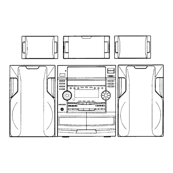
This service manual consists of "DC-F43OAVU"(Main unit),
I
control) and "SX-F430"(FrontSpeaker
system) and "SX-CE43O"(Center Speaker system) and "SX-
- - - - - - - - - - - - - - - - - - -l
Mini Component System
PARTS LIST . . . . . . . . . . . . . . . . . . . . . . . . . . . . . . . . . . . . . . . . . . . . . . . . . . . . . . . . . . . . . . . . . . . . . . . . . . . 17
EXPLODED VIEW (TAPE MECHANISM) . . . . . . . . . . . . . . . . . . . . . . . . . . . . . . 26
EXPLODED VIEW (CD CHANGER MECHANISM) . . . . . . . . . . . . . . . 28
IC BLOCK DIAGRAM 81 DESCRIPTION . . . . . . . . . . . . . . . . . . . . . . . . . . . . . . . 31
IC & TRANSISTOR VOLTAGES . . . . . . . . . . . . . . . . . . . . . . . . . . . . . . . . . . . . . . . . . . . . 40
SCHEMATIC DIAGRAM . . . . . . . . . . . . . . . . . . . . . . . . . . . . . . . . . . . . . . . . . . . . . . . . . . . . . . . . . 41
WIRING DIAGRAM . . . . . . . . . . . . . . . . . . . . . . . . . . . . . . . . . . . . . . . . . . . . . . . . . . . . . . . . . . . . . . . . . 53
WIRING CONNECTION . . . . . . . . . . . . . . . . . . . . . . . . . . . . . . . . . . . . . . . . . . . . . . . . . . . . . . . . . .
IC & TRANSISTOR VOLTAGES . . . . . . . . . . . . . . . . . . . . . . . . . . . . . . . . . . . . . . . . . . . . 64
1
I
FILE NO.
(UK)
PRODUCT CODE No.
129 530 06(UK)
129 530 07(XE)
REFERENCE No. SM580901
I
63
Advertisement
Table of Contents

Related Manuals for Sanyo DC-F430AV


Summary of Contents for Sanyo DC-F430AV
-
Page 1: Table Of Contents
FILE NO. (UK) Service Manual Mini Component System CONTENTS PRODUCT CODE No. 129 530 06(UK) 129 530 07(XE) PARTS LIST ................17 SPECIFICATION .............. -
Page 2: Specification
SPECIFICATIONS Note: The below mentioned specifications are mainly based on the IHF measurements Standard. They tan therefore not directly be compared with specifications based on the DIN Standard or other Standards. Speaker Systems Tuner section FRONT SPEAKER SYSTEM(SX-F430) 87.5 MHz 108 MHz Type ......... -
Page 3: Laser Beam Safety Precaution
LASER BEAM SAFETY PRECAUTION Pick-up that emits a laser beam is used in this CD player section. not look directry at the laser beam coming from the pick-up This model has a disc chuck lever and top lid. This disc check or allow it to Strike against your fingers, skin, etc. - Page 4 REMOVAL & INSTALLATION 4 . C D M E C H A N I S M 3. FRONT PANEL BLOCK 1. Remove the 4 CD MECHANISM mounting screws.@) 1. Remove the 2 FRONT PANEL mounting screws.@) 2. Remove the claw of PRE-AMPLIFIER P.W.Board.@) 6 .
-
Page 5: Tuner Adjustment
TUNER ADJUSTMENTS Use a plastic screw driver for adjustments. MODE : STEREO Speaker impedance : 6 ohm TUNING FM : 87.5 - 108.0 MHz (50kHz step) MW : 522 - 1710 kHz (9kHz step) LW : 144 - 288 kHz (9kHz step) L2153 CT252 CT251... -
Page 6: Cd Changer Operation Description
CD CHANGER OPERATION DESCRIPTION This set is capable of stocking and playing up to 3 CDs. While playing a CD, other discs can be replaced. In this case, press the button for the disc No. you wish to remove, and then press the OPEN/CLOSE button. When the “POWER”... - Page 7 CD CAHNGER OPERATION DESCRIPTION 4. When the TRAY closes and it reaches the tip of RIB part of LEFT TRAY GUIDE, the LOCK LEVER is lowered to release TRAY GUIDE HOLDER the TRAY, and loading proceeds. LOCK LEVER TRAYRELEASE TRAY LOCK (2)LOADING 1.
-
Page 8: Cdchangerreplacement
CDCHANGERREPLACEMENT RAGE 1. LOAD/UNLOAD FUNCTION CHUCK SRACK 1. Remove the B TOP ENCOURAGE. 2. Remove the CD MECHANISM. 2 . HOW TO REMOVE THE TRAYS 1. Remove the CHUCK BRACKET.@ - 0) MECHANISM 2. Rotate the UP/DOWN CAM GEAR and position the collar 3. - Page 9 CD CHANGER REPLACEMENT 4. LEFT SLIDE BRACKET EM-50L ....... MOLYKOTE, EM-50L SG-7 .
-
Page 10: Cd Mechanism Adjustment
CDCHANGERREPLACEMENT UP/DOWN DRIVE GEAR 1 10. SETTING UP THE TRAY HOLDER AND UP/DOWN DRIVE GEAR 1. Loosen and install the SET SCREW of the SENSOR P.W.B. 2. Slide the TRAY HOLDER SLIDE forward until it goes no further. 3. Align the round mark on the UP/DOWN DRIVE GEAR 1 with the mark area on the TRAY HOLDER SLIDE, and install. - Page 11 CD MECHANISM ADJUSTMENTS 3 . C D M E C H A N I S M (1)Replacement of the spindle motor B O N D First, prepare the new turntable and new special washer for replacement. The removed turntable will be deformed by the heat of the soldering iron, and cannot be reused.
-
Page 12: Cd Player Adjustments
Clean the lens with the specified cleaning disc or moisten a cotton swab with isopropyl alcohol and cleaning paper. Specified cleaning disc : LC-1 (Part code : 645 026 1961 ..manufactured by SANYO.) Regarding procedure of cleaning with moisten cotton swab, please refer to the attached as follows. - Page 13 CD PLAYER ADJUSTMENTS 4. ADJUSTMENTS Adjustment value Measuring Service output Adjustment Adjustment location instrument mode connection Item TP3 : TE Waveform symmetry Tracking Oscilloscope TR4 : VC balance Check be sure that the “eye” Checking pattern is at the center of the Oscilloscope the “eye”...
-
Page 14: Tape Deck Adjustments
TAPE DECK ADJUSTMENTS Adjust Adjustment Item Measuring Adjust Test Tape Instrument location value HEAD AZIMUTH (1) HEAD AZIMUTH VTr-738 AC-voltmeter SCREW (FWDIREV) TAPE “A” (2) HEAD AZIMUTH in-r-738 AC-voltmeter HEAD AZIMUTH SCREW T A P E “B” FREQUENCY COMPUTER REC (TAPE “A”) (3) MOTOR SPEED M-IT-21 1... - Page 15 TAPE DECK ADJUSTMENTS (3)Motor speed SPEED HIGH 1. insert the test tape (TCW-211 or etc. 1,500 Hz optional) FM MODE 0 into Tape “A” or “B”. (Cancel service mode) 2. Press the “FM MODE & SOUND PRESET” buttons at the same time.(O) 3.
-
Page 16: Exploded View (Cabinet 81 Chassis)
EXPLODED VIEW (CHASSIS) _ _ I... - Page 17 EXPLODED VIEW (CABINET)
-
Page 18: Parts List
PARTS LIST PRODUCT SAFETY NOTICE EACH PRECAUTION IN THIS MANUAL SHOULD BE FOLLOWED DURING SERVICING. COMPONENTS IDENTIFIED WITH THE IEC SYMBOL IN THE PARTS LIST AND THE SCHEMATIC DIAGRAM DESIGNATED COMPONENTS IN WHICH SAFETY CAN BE OF SPECIAL SIGNIFICANCE. WHEN REPLACING A COMPONENT IDENTIFIED BY USE ONLY THE REPLACEMENT PARTS DESIGNATED, OR PARTS WITH THE SAME RATINGS OF RESISTANCE, WAlTAGE OR VOLTAGE THAT ARE DESIGNATED IN THE PARTS LIST IN THIS MANUAL. - Page 19 PARTS LIST REF.NO. PART NO. DESCRIPTION REF.NO. PART NO. DESCRIPTION C 4 7 2 7 4 0 3 0 5 7 2 4 0 7 POLYESTER 0.1 U J 50V Y 0 6 411 020 9506 SCR S-TPG BRZ+FLG 3X1 6, 4 0 3 1 8 5 0 1 0 8 MT-POLYEST 0.47U J 50V...
- Page 20 PARTS LIST REF.NO. PART NO. DESCRIPTION REF.NO. PART NO. DESCRIPTION L O O 0 1 405 033 6805 T R 2SDl468SS 645 006 1417 Q 4 8 7 0 LOO02 645 006 1417 405 033 6706 T R 2SDl468SR L G 4 9 3 645 023 8987 FIXER 405 033 6805...
- Page 21 PARTS LIST PRE-AMPLFIER & TUNER P.W.BOARD(N:S.P) PART NO. REF.NO. DESCRIPTION REF.NO. PART NO. D E S C R I P T I O N A 645 014 2536 PR401 6142958353 4050207402 TR 2SC945A-P c2152 4030820201 POLYPRO 470P J 1OOV 405020 7204 TR 2SC945A-K C 2 1 5 5 4030822205...
- Page 22 PARTS LIST REF.NO. PART NO. DESCRIPTION REF.NO. PART NO. DESCRIPTION T4001 614 239 1839 TERMINAL 4 0 5 0 2 0 7 2 0 4 TR 2SC945A-K TUNER 6450177279 405 405 012 000 2002 0508 X2301 645 010 0024 4 0 5 0 7 8 2 3 0 5 TR BNl A4M 6142460870 RESONATOR...
- Page 23 PARTS LIST PART NO. DESCRIPTION REF.NO. PART NO. DESCRIPTION 408 037 4204 LED SLP-31188-51 HAB-Tl, 6 1 4 2 2 0 5471 D 6 5 0 4 FUNTION-GREEN 6 1 4 2 4 0 1 0 0 2 5 6 1 0 2 D 6 5 0 5 408 037 4204 LED SLP-3118B-51HAB-Tl ,...
- Page 24 PARTS LIST PART NO. DESCRIPTION REF.NO. PART NO. DESCRIPTION REF.NO. 407 007 9904 D I O D E G M A O l 6 4 5 0 0 6 5 9 5 8 407 012 4406 DIODE lSS133 6 1 4 2 2 0 5471 407 007 9904 D I O D E G M A O l D 3 6 3 2...
- Page 25 PARTS LIST REF.NO. PART NO. DESCRIPTION REF.NO. PART NO. DESCRIPTION 405 020 7204 T R 2SC945A-K 0 3 7 0 1 405 075 8409 T R DTCl44TS 405 105 7204 T R BAl L4Z 405 141 3307 T R KTC3198-GR 405 141 3208 T R KTC3198-Y 405 011 8609...
- Page 26 PARTS LIST FRONT SPEAKER,SX-F430/SS PART NO. DESCRIPTION T M 0 2 3 6450278846 ASSIST-GEAR REF.NO. PART NO. DESCRIPTION T M 0 2 4 6450280559 ASSY.FF-GEAR 6 4 5 0 2 5 6 9 5 0 T M 0 2 5 6450242229 ASSY,CENTER-GEAR 6 1 4 2 9 7 6 2 2 7...
-
Page 27: Exploded View (Tape Mechanism)
EXPLODED VIEW (TAPE DECK MECHANISM) $ - T M 0 0 7 -TM062 TM059 T M 0 6 5 TM079 TM067 - T M 0 9 1 TM077... - Page 28 EXPLODED VIEW & PART LIST (CD CHANGER & BASE MECHANISM) CD BASE SECTION (PM-CDBM94D2/SH) (N.S.P) REF.NO. PART NO. DESCRIPTION 6 1 4 2 7 0 2031 701-l 6 1 4 2 6 8 3 3 5 4 701-2 411 0 4 4 7 5 0 2 SCR PAN+SW 2X5,SPINDLE MOTOR 6 1 4 2 6 2 2 5 8 2 701-3...
-
Page 29: Exploded View (Cd Changer & Base Mechanism). 27 Exploded View (Cd Changer Mechanism)
E X P L .ODED VIEW (CD CHANGER MECHANISM)PARTl)) - Page 30 PARTS LIST MECHANISM (PM-CD98CHZlKH). . . N.S.P REF.NO. PART NO. DESCRIPTION 6142983812 JOINT,F-TOP ENCOURAGE CHANGER SECTION(PART 1) 5 8 2 4110282905 SCR S-TPG PAN 2X4,JOINT FIX REF.NO. PART NO. DESCRIPTION 5 8 3 6142863343 411 022 7500 SCR S-TPG PAN 2X4,CHUCK PULLEY 5 8 4 411 028 3100 SCR S-TPG PAN 2X6,HOLDER FIX...
- Page 31 EXPLODED VIEW (CD CHANGER MECHANISM(PART2)) 6 1 3 - C 6 0 2 PARTS LIST CD CHANGER MECHANISM(PART2) REF.NO. PART NO. DESCRIPTION REF.NO. PART NO. DESCRIPTION 411 0 9 8 8 8 0 7 SCR S-TPG BRZ+FLG 3X6,GEAR 411 0 9 8 8 8 0 7 SCR S-TPG BRZ+FLG 3X6,LUG 6 0 2 6 1 4 2 6 6 1 7 5 8...
-
Page 32: Ic Block Diagram 81 Description
(SERVO SIGNAL PROCESSOR) NAME 1 VO 1 Function bottom hold output Input pin for the 0 c c 2 capacitance-coupled. DEFECT bottom hold output. Connection oin for DEFECT bottom hold pin for MIRR h o l d non-inverted input. ’ Ground this pin through a capacitor when decreas-ing the focus servo high-frequency gain. - Page 33 V R E C MUTE IN A IN S OUT A D R I V E B U F F E R Function No. 1 Pin Name 1 VO 1 V S S CH1 negative output. Driver CH1 positive output. CHI-OUT B Driver CH1 input.
- Page 34 Digital Fi..ter lbit LRCK WDCK digital RFCK SQCK SQSO EXCK SBSO MNT3 SCOR XLON to c SPOA WFCK CLOK EMPH XLAT demodulato DATA XUGF SENS GTOP CLKO Servo auto XLTO sequencer XTSL 18 DATO...
- Page 35 Function No. Pin Name VO SCOR D/A interface for 48-bit slot. Ward clock (f = Turns [H] when sync SO or SI is detected. S B S O Serial output of sub-code P - W. D/A interface for 48-bit slot. LR clock (f = FS). E X C K Clock input for reading SBSO.
- Page 36 ICI32 LB1641 L O U T 2 O U T 1 IC231 LA1 832ML I N 2 input Output IN1 / IN2 1 OUT1 1 OUT2 / Brake...
- Page 37 C L K DATA ENABLE V R E F S-CH DC OUT C-CH DC OUT L-CH DC OUT R-CH DC OUT V R E F L-IN R - O U T R-IN S - O U T C - O U T C M O D E - C A P .
- Page 38 IC421 LV1016 AGND L-MIX-OUT R-MIX-OUT DELAY-OUT Vcc L-IN R-IN S-IN is CLK DATA ENABLE B-NR lC453 BA3842F BASS BOOST PRESET...
- Page 39 Function OUTPUT PASS TRANSISTOR OUTPUT G N D SELECT V E E R I N L I N f 05 f 06 R E S E T...
- Page 40 NO. 1 NAME DESCRIPTION DESCRIPTION N A M E KEY2 input. G 1 3 PULL UP Pull up power supply. L C D g r i d output. EX CLKO L C D g r i d output. EX CLKl output.
-
Page 41: Ic & Transistor Voltages
ICI32 LB1641 No. 1 33 1 34 C D S T O P 1 0 . 0 0 . 0 2 . 9 C D S T O P 1 0 . 0 0 . 0 0 . 0 0 . 0 0 . -
Page 42: Schematic Diagram
SCHEMATIC DIAGRAM (CD) IECHANISM Remark : All parts are changed without prior notice. This is a basic schematic diagram. - Page 43 PRODUCT SAFETY NOTICE Each precaution in this manual should be followed during servicing. Components identified with the IEC symbol A in the pans list and the schematic diagram designated components in which safety can be of special significance. When replacing a component identified by , use only the replacement pans designated, or with the same ratinos of resistance, wattage or voltage that are designated in the parts list in this manual.
- Page 45 I I I PRODUCT SAFETY NOTICE Each precaution in this manual should be followed during servicing. Components identified with the IEC symbol A in the pans list and the schematic diagram designated components in which safety can be of special significance. When replacing a component identified by , use only the replacement parts designated, or parts with the same ratings of resistance, wattage or voltage that are designated in the parts list in this manual.
- Page 46 SCHEMATIC DIAGRAM (FRONT) 56001 LAMP PWB Remark : All parts are changed without prior notice. This is a basic schematic diagram.
- Page 47 PRODUCT SAFETY NOTICE Each precaution in this manual should be followed during servicing. Components identified with the IEC symbol A in the parts list and the schematic diagram designated components in which safety can be of special significance. When replacing a component identified by use only the replacement pans designated, or parts with the same ratings of resistance, wattage or voltage that are designated in the...
- Page 48 SCHEMATIC DIAGRAM (POWER) FRONT L/R AMP FRONT CENTER CENTER / SURROUND AMP Remark : All parts are changed without prior notice. This is a basic schematic diagram.
- Page 49 PRODUCT SAFETY NOTICE Each precaution in this manual should followed during servicing. Components identified with the IEC symbol A in the parts list and the schematic diagram designated components in which safety can be of special significance. When replacing A , u s e a component identified by only the replacement parts designated, or...
- Page 50 SCHEMATIC DIAGRAM (PRE-AMP) PRODUCT SAFETY NOTICE Each precaution in this manual should be followed during servicing. Components identified with the IEC symbol A in the parts list and the schematic diagram designated components in which safety can be of special significance. A , use When replacing a component identified by only...
- Page 51 C N 4 2 2 TO FRONT C N 4 2 4 TO AMP TO DECK...
- Page 52 SCHEMATIC DIAGRAM (TUNER) Remark : All parts are changed without prior notice. This is a basic schematic diagram.
- Page 53 PRODUCT SAFETY NOTICE Each precaution in this manual should be followed during servicing. Components identified with the IEC symbol and the schematic diagram designated components in which safety can be of special significance. When replacing a component identified by , use only the replacement parts designated, or parts with the same ratings of resistance, wattage or voltage that are designated in the parts list in this manual.
-
Page 54: Wiring Diagram
WIRING DIAGRAM (CD) - Page 55 WIRING DIAGRAM (LAMP, PTl , PT2, MOTOR & LIMIT SW, SENSOR & CONNECTOR) - LAMP MOTOR & LIMIT SW SENSOR & CONNECTOR...
- Page 56 WIRING DIAGRAM (DECK)
- Page 58 WIRING DIAGRAM (FRONT)
- Page 60 WIRING DIAGRAM (POWER) CENTER SURROUND SPEAKERS FRONT SPEAKERS SUB Ob'&OFE...
- Page 62 WIRING DIAGRAM (PRE-AMP & TUNER)
-
Page 64: Wiring Connection
WIRING CONNECTION PRE-AMPLIFIER TAPE DECK MECHANISM SENSOR SENSOR... -
Page 65: Ic & Transistor Voltages
P L A Y S T O P Pin No. P L A Y S T O P IC131 LB1648 I 1 I 2 I Pin No. UNLOAD... - Page 66 Electric Co., Ltd. SANYO Osaka, Japan Apr. / ‘98 / 2300 NS Printed in Japan...
Need help?
Do you have a question about the DC-F430AV and is the answer not in the manual?
Questions and answers