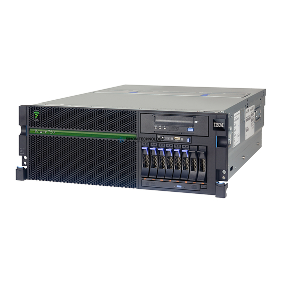
IBM Power 720 Express 8202-E4B Installation Manual
Hide thumbs
Also See for Power 720 Express 8202-E4B:
Table of Contents
Advertisement
Quick Links
- 1 Installing the Ibm Power 720 Express (8202-E4B) and the Ibm Power 740 Express (8205-E6B)
- 2 Connecting the Power Cables to the System
- 3 Cabling the Server and Setting up the Console
- 4 Cabling the Server to the Sdmc
- 5 Cabling the Server with an Ascii Terminal
- 6 Cabling the Server to the Hardware Management Console
- 7 Cabling the Server and Accessing Operations Console
- 8 Completing Server Setup if You Have an Hmc
- Download this manual
Advertisement
Table of Contents

Related Manuals for IBM Power 720 Express 8202-E4B


Summary of Contents for IBM Power 720 Express 8202-E4B
- Page 1 Power Systems Installing the IBM Power 720 Express (8202-E4B) and IBM Power 740 Express (8205-E6B) GI11-9821-02...
- Page 3 Power Systems Installing the IBM Power 720 Express (8202-E4B) and IBM Power 740 Express (8205-E6B) GI11-9821-02...
- Page 4 Before using this information and the product it supports, read the information in “Safety notices” on page v, “Notices” on page 41, the IBM Systems Safety Notices manual, G229-9054, and the IBM Environmental Notices and User Guide, Z125–5823. This edition applies to IBM Power Systems servers that contain the POWER7 processor and to all associated models.
-
Page 5: Table Of Contents
Safety notices ....... . . v Installing the IBM Power 720 Express (8202-E4B) and the IBM Power 740 Express (8205-E6B) . - Page 6 Power Systems: Installing the IBM Power 720 Express (8202-E4B) and IBM Power 740 Express (8205-E6B)
-
Page 7: Safety Notices
Laser safety information ® servers can use I/O cards or features that are fiber-optic based and that utilize lasers or LEDs. Laser compliance IBM servers may be installed inside or outside of an IT equipment rack. © Copyright IBM Corp. 2010, 2011... - Page 8 Electrical voltage and current from power, telephone, and communication cables are hazardous. To avoid a shock hazard: v Connect power to this unit only with the IBM provided power cord. Do not use the IBM provided power cord for any other product.
- Page 9 Observe the following precautions when working on or around your IT rack system: v Heavy equipment–personal injury or equipment damage might result if mishandled. v Always lower the leveling pads on the rack cabinet. v Always install stabilizer brackets on the rack cabinet. v To avoid hazardous conditions due to uneven mechanical loading, always install the heaviest devices in the bottom of the rack cabinet.
- Page 10 Also lower the leveling pads to raise the casters off of the pallet and bolt the rack cabinet to the pallet. (R002) (L001) (L002) viii Power Systems: Installing the IBM Power 720 Express (8202-E4B) and IBM Power 740 Express (8205-E6B)
- Page 11 (L003) All lasers are certified in the U.S. to conform to the requirements of DHHS 21 CFR Subchapter J for class 1 laser products. Outside the U.S., they are certified to be in compliance with IEC 60825 as a class 1 laser product.
- Page 12 Exchange only with the IBM-approved part. Recycle or discard the battery as instructed by local regulations. In the United States, IBM has a process for the collection of this battery. For information, call 1-800-426-4333. Have the IBM part number for the battery unit available when you call. (C003)
-
Page 13: Installing The Ibm Power 720 Express (8202-E4B) And The Ibm Power 740 Express (8205-E6B)
IBM Power 740 Express (8205-E6B). Before you install your server, read the following items: The latest version of this document is maintained online. For the online version, see Installing the IBM Power 720 Express (8202-E4B) and the IBM Power 740 Express (8205-E6B): Overview (http://publib.boulder.ibm.com/infocenter/systems/scope/hw/topic/p7eda/p7edaroadmap.htm). - Page 14 Remove the shipping cover on the back of the system. Remove the tape that adheres the shipping cover to the This cover is not needed for system installation. system. Power Systems: Installing the IBM Power 720 Express (8202-E4B) and IBM Power 740 Express (8205-E6B)
- Page 15 Connect power cables and apply power. For more information, see Completing server setup if you have an HMC, or Completing server setup if you do not have an HMC Installing the IBM Power 720 Express (8202-E4B) and the IBM Power 740 Express (8205-E6B)
- Page 16 Install the front cover door The following pictures describe how to install the front cover door. To install the rack-mounted 8202-E4B and 8205-E6B, perform the following high-level tasks: Power Systems: Installing the IBM Power 720 Express (8202-E4B) and IBM Power 740 Express (8205-E6B)
- Page 17 (Select your location to view the service and support contact information.) You can also obtain order information from your marketing representative or IBM Business Partner. Installing the IBM Power 720 Express (8202-E4B) and the IBM Power 740 Express (8205-E6B)
- Page 18 Verify that you have a rack, if you need one. You must first have a rack installed. If you do not have a rack installed, see Installing the rack (http://publib.boulder.ibm.com/infocenter/systems/ scope/hw/topic/p7hbf/installrack.htm). Power Systems: Installing the IBM Power 720 Express (8202-E4B) and IBM Power 740 Express (8205-E6B)
- Page 19 IBM Rochester manufacturing automated information line at 1-800-300-8751 (United States only). v Directory of worldwide contacts at http://www.ibm.com/planetwide. (Select your location to view the service and support contact information.) Installing the IBM Power 720 Express (8202-E4B) and the IBM Power 740 Express (8205-E6B)
- Page 20 Note: Do not power on your system until you return to Disk drives (http://publib.boulder.ibm.com/infocenter/ this guide. systems/scope/hw/topic/p7hal/p7halkickoff.htm), and Model 8202-E4B or 8205-E6B PCI adapters (http://publib.boulder.ibm.com/infocenter/systems/ scope/hw/topic/p7hak/p8202pcianddiv.htm). When you are finished, continue with the next task. Power Systems: Installing the IBM Power 720 Express (8202-E4B) and IBM Power 740 Express (8205-E6B)
- Page 21 Connect power cables and apply power. For more information, see Completing server setup if you have an HMC, or Completing server setup if you do not have an HMC Installing the IBM Power 720 Express (8202-E4B) and the IBM Power 740 Express (8205-E6B)
- Page 22 Power Systems: Installing the IBM Power 720 Express (8202-E4B) and IBM Power 740 Express (8205-E6B)
-
Page 23: Installing The Server Into A Rack
177.8 mm (7 in.) high and covers 12 mounting holes in the rack. 3. If necessary, remove the filler panels to allow access to the inside of the rack enclosure where you plan to place the unit. © Copyright IBM Corp. 2010, 2011... -
Page 24: Marking The Location
Make a note of the EIA location. Use tape, a marker, or a pencil to mark the bottom hole of this EIA unit A. Mark the rack so the mark can also be seen from the rear of the rack. Power Systems: Installing the IBM Power 720 Express (8202-E4B) and IBM Power 740 Express (8205-E6B) -
Page 25: Attaching The 8202-E4B Or 8205-E6B Mounting Hardware To The Rack
Do not install mismatched hardware using washers or spacers. If you do not have the correct rails and fittings for your rack, contact your IBM reseller. Also, to install the rails correctly, perform each task in the following order. - Page 26 3. Pull the slide rail forward and insert the two pins (1) in Figure 5 on page 15 on the front of the rail into the two previously-marked holes in the front of the rack. Drop the rail into place until it clicks into place. Power Systems: Installing the IBM Power 720 Express (8202-E4B) and IBM Power 740 Express (8205-E6B)
- Page 27 Figure 5. Rack front rail with pins seated 4. Push the front latch (2) in Figure 6 in all the way. Make sure that the latch is fully seated. Figure 6. Rack front rail with latch seated Note: If you need to reposition the rail, release the front latch and push the rail toward the back of the rack.
-
Page 28: Installing The Cable-Management Arm
To install the cable-management arm, complete the following steps: Note: The procedure for installing the cable-management arm involves the assembly of the following parts: Support arm Power Systems: Installing the IBM Power 720 Express (8202-E4B) and IBM Power 740 Express (8205-E6B) - Page 29 Cable-management stop bracket Mounting bracket Cable-management arm The following figure shows the parts of the cable-management arm in relative position to each other before their assembly. Figure 9. Relative positions of cable-management arm parts before assembly 1. The cable-management arm must be installed on the right side of the server, when you are facing it from the rear.
- Page 30 4. Pull out the mounting bracket pin (1) and slide the mounting bracket (2) into the right slide rail. Push the bracket into the slide rail until the spring-loaded pin snaps into place. Power Systems: Installing the IBM Power 720 Express (8202-E4B) and IBM Power 740 Express (8205-E6B)
- Page 31 Figure 13. Mounting bracket pin extended and mounting bracket installed into slide rail 5. Place the cable-management arm on the support arm. Pull out the cable-management arm pin (1), and then slide the cable-management arm tab (2) into the slot on the inside of the right slide rail. Push the tab until it snaps into place.
-
Page 32: Connecting The Power Cables To The System
If the operator panel does not display a blinking green LED, see “Common system attention LEDs and system reference codes” on page 39. Power Systems: Installing the IBM Power 720 Express (8202-E4B) and IBM Power 740 Express (8205-E6B) -
Page 33: Cabling The Server And Setting Up The Console
1. Verify that line cords are plugged in correctly in the related errors draw, power distribution unit (PDU) (if applicable), battery backup unit (BBU) (if applicable), and input source power receptacle. 2. Verify that the Power Supplies are fully seated and latched into position. © Copyright IBM Corp. 2010, 2011... -
Page 34: Cabling The Server To The Sdmc
Using service applications, the SDMC communicates with hosts to detect, consolidate, and forward information to IBM service for analysis. Power Systems: Installing the IBM Power 720 Express (8202-E4B) and IBM Power 740 Express (8205-E6B) -
Page 35: Cabling The Server With An Ascii Terminal
Ethernet Connector 1 on the SDMC to the LINK HMC1 port on the managed system. To learn more about connecting an SDMC to a private network so that it can manage more than one managed system, see Configuring the network (http://publib.boulder.ibm.com/infocenter/director/ v6r2x/topic/dpsm/dpsm_managing_console/configuringnetwork.html). -
Page 36: Cabling The Server To The Hardware Management Console
HMC to the LINK HMC1 port on the managed system. To learn more about connecting an HMC to a private network so that it can manage more than one managed system, see HMC network connections (http://publib.boulder.ibm.com/infocenter/systems/scope/hw/topic/p7hai/ netconhmc.htm). Power Systems: Installing the IBM Power 720 Express (8202-E4B) and IBM Power 740 Express (8205-E6B) -
Page 37: Cabling The Server And Accessing Operations Console
Sign on to the PC by using the local administrator account. b. Ensure that you have installed a full version of IBM i Access with the latest service pack. The Web site to download the latest service pack for IBM i Access can be found at IBM i Access (http://www-03.ibm.com/systems/i/software/access/windows/casp.html). - Page 38 3) Tape this information on the console PC as a reminder to reset it before reconnecting to the network. c. Change the TCP/IP settings. Note: Some versions of IBM i require that the gateway address respond to pings before the console LAN adapter activates. Configure the PC with the default gateway IP address by doing the following: 1) Set the IP address to the opcon LAN adapter gateway.
- Page 39 For IBM i V5R4 and earlier only: The service tool console IP address can be specified as the name. 2) If you are using IBM i V5R4, set the target partition to 1. If you are using IBM i V6R1 and later, press the Tab key. The Service TCP/IP Address field is enabled.
-
Page 40: Cabling The Server And Accessing The Integrated Virtualization Manager
Note: You should configure and start an IBM i TCP interface on a second port (T2, T3, T4) prior to moving the console. This action ensures there is an alternate method to access the server. Use the information in step 3b to reset the PC to its original TCP/IP settings. -
Page 41: Supporting Information For Setting Up Consoles
f. Select Normal Boot, and confirm that you want to exit SMS. 5. Install the Virtual I/O Server: a. Select the console, and press Enter. b. Select a language for the BOS menus, and press Enter. c. Select Start Install Now with Default Settings. d. -
Page 42: Setting The Ip Address On Your Pc Or Notebook
IP address on a PC or notebook running the Linux operating system and the Microsoft Windows XP, 2000, and Vista operating systems. Power Systems: Installing the IBM Power 720 Express (8202-E4B) and IBM Power 740 Express (8205-E6B) -
Page 43: Windows Xp And Windows 2000
You will need the information you recorded in step 4 on page 30 in Accessing the ASMI using a Web browser to complete the following procedure. Windows XP and Windows 2000 To set the IP address within Windows XP and Windows 2000, do the following steps: 1. -
Page 44: Correcting An Ip Address
Move the reset toggle switches on the service processor from their current position to the opposite position. To perform this task, you must remove and replace the service processor. For details, contact your next level of support. Power Systems: Installing the IBM Power 720 Express (8202-E4B) and IBM Power 740 Express (8205-E6B) -
Page 45: Completing Server Setup
Select Operations > Launch Advanced System Management (ASM). To change the time of day using the ASMI, do the following steps: a. On the Launch ASMI pane, select the primary Service processor and click OK. © Copyright IBM Corp. 2010, 2011... -
Page 46: Completing Server Setup If You Have An Hmc
You must perform these tasks to complete server setup with a Hardware Management Console (HMC). To manage POWER7 systems, the HMC must be at Version 7.7.2 or later. To complete server setup with an HMC, do the following steps: Power Systems: Installing the IBM Power 720 Express (8202-E4B) and IBM Power 740 Express (8205-E6B) - Page 47 Compare your installed firmware level with available firmware levels. From a computer or server with an Internet connection, go to http://www.ibm.com/eserver/support/fixes. b. If required, update your managed system firmware levels. In the navigation area, select Updates. c. In the contents area, select your managed system.
-
Page 48: Completing Server Setup If You Do Not Have An Hmc
For instructions to install the Linux operating system, see Installing Linux on Power Systems servers (http://publib.boulder.ibm.com/infocenter/lnxinfo/v3r0m0/topic/liaae/ lcon_Installing_Linux_on_System_p5.htm). For instructions to install the VIOS operating system, see Installing VIOS (http:// publib.boulder.ibm.com/infocenter/systems/scope/hw/topic/p7hch/iphchinstallvios.htm). 6. Update the system firmware, if required. Power Systems: Installing the IBM Power 720 Express (8202-E4B) and IBM Power 740 Express (8205-E6B) - Page 49 AIX or Linux without an HMC (http://publib.boulder.ibm.com/ infocenter/systems/scope/hw/topic/p7ha5/fix_firm_no_hmc_aix.htm). v If you are using IBM i, use the IBM i PTF installation functions to install the server firmware fixes. v If you are using VIOS, see Updating the Virtual I/O Server's firmware and device microcode with an Internet connection (http://publib.boulder.ibm.com/infocenter/systems/scope/hw/topic/...
- Page 50 Power Systems: Installing the IBM Power 720 Express (8202-E4B) and IBM Power 740 Express (8205-E6B)
-
Page 51: Common System Attention Leds And System Reference Codes
Whenever a cable is not installed, ensure a wrap plug is and ends with installed for each unused port. Wrap plugs are shipped xxxx3120, xxxx3121 automatically when a fiber channel feature code is ordered. © Copyright IBM Corp. 2010, 2011... - Page 52 System reference code Error description Recovery steps B1A38B24 Network configuration An invalid network configuration was entered by the user. Often, a duplicate IP address was entered. Power Systems: Installing the IBM Power 720 Express (8202-E4B) and IBM Power 740 Express (8205-E6B)
-
Page 53: Notices
All statements regarding the manufacturer's future direction or intent are subject to change or withdrawal without notice, and represent goals and objectives only. The manufacturer's prices shown are the manufacturer's suggested retail prices, are current and are subject to change without notice. Dealer prices may vary. © Copyright IBM Corp. 2010, 2011... -
Page 54: Trademarks
IBM, the IBM logo, and ibm.com are trademarks or registered trademarks of International Business Machines Corp., registered in many jurisdictions worldwide. Other product and service names might be trademarks of IBM or other companies. A current list of IBM trademarks is available on the web at Copyright and trademark information at www.ibm.com/legal/copytrade.shtml. - Page 55 Properly shielded and grounded cables and connectors must be used in order to meet FCC emission limits. IBM is not responsible for any radio or television interference caused by using other than recommended cables and connectors or by unauthorized changes or modifications to this equipment.
- Page 56 Declaration: This is a Class A product. In a domestic environment this product may cause radio interference in which case the user may need to perform practical action. Power Systems: Installing the IBM Power 720 Express (8202-E4B) and IBM Power 740 Express (8205-E6B)
- Page 57 Um dieses sicherzustellen, sind die Geräte wie in den Handbüchern beschrieben zu installieren und zu betreiben. Des Weiteren dürfen auch nur von der IBM empfohlene Kabel angeschlossen werden. IBM übernimmt keine Verantwortung für die Einhaltung der Schutzanforderungen, wenn das Produkt ohne Zustimmung von IBM verändert bzw.
-
Page 58: Class B Notices
This equipment has been tested and found to comply with the limits for a Class B digital device, pursuant to Part 15 of the FCC Rules. These limits are designed to provide reasonable protection against harmful interference in a residential installation. Power Systems: Installing the IBM Power 720 Express (8202-E4B) and IBM Power 740 Express (8205-E6B) - Page 59 Properly shielded and grounded cables and connectors must be used in order to meet FCC emission limits. Proper cables and connectors are available from IBM-authorized dealers. IBM is not responsible for any radio or television interference caused by unauthorized changes or modifications to this equipment.
- Page 60 IBM Taiwan Contact Information Electromagnetic Interference (EMI) Statement - Korea Germany Compliance Statement Deutschsprachiger EU Hinweis: Hinweis für Geräte der Klasse B EU-Richtlinie zur Elektromagnetischen Verträglichkeit Power Systems: Installing the IBM Power 720 Express (8202-E4B) and IBM Power 740 Express (8205-E6B)
-
Page 61: Terms And Conditions
Permissions for the use of these publications are granted subject to the following terms and conditions. Applicability: These terms and conditions are in addition to any terms of use for the IBM website. Personal Use: You may reproduce these publications for your personal, noncommercial use provided that all proprietary notices are preserved. - Page 62 IBM reserves the right to withdraw the permissions granted herein whenever, in its discretion, the use of the publications is detrimental to its interest or, as determined by IBM, the above instructions are not being properly followed. You may not download, export or re-export this information except in full compliance with all applicable laws and regulations, including all United States export laws and regulations.
- Page 64 Part Number: 16R3036 Printed in USA GI11-9821-02...
Need help?
Do you have a question about the Power 720 Express 8202-E4B and is the answer not in the manual?
Questions and answers