Table of Contents
Advertisement
Quick Links
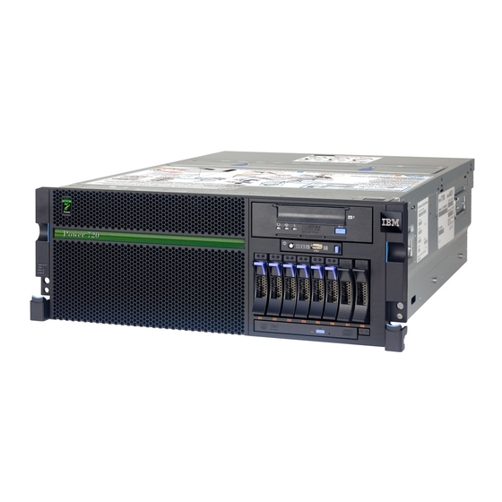
IBM Power 720 and 740
Technical Overview and
Introduction
Features 8202-E4D and 8205-E6D servers based
on POWER7+ processor technology
Describes the support of 20
partitions per core
Explores leading performance
on entry servers
ibm.com/redbooks
Front cover
Redpaper
James Cruickshank
Sorin Hanganu
Volker Haug
Stephen Lutz
John T Schmidt
Marco Vallone
Advertisement
Table of Contents


Need help?
Do you have a question about the Power 720 and is the answer not in the manual?
Questions and answers