
Related Manuals for PowerWalker VFI 3/3 Series


Summary of Contents for PowerWalker VFI 3/3 Series
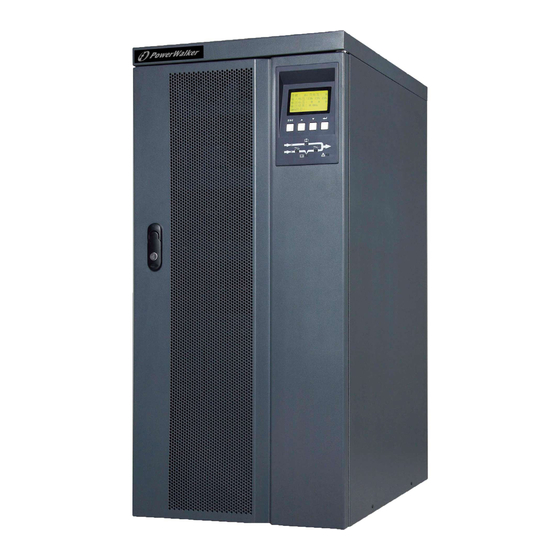
- Page 1 PowerWalker VFI 3/3 Series VFI 20000TP~40000TP 3/3 BX 380/400/415V 50/60Hz (3-phase input/output) User Guide...
- Page 3 ©2013 BlueWalker GmbH All Rights Reserved The contents of this manual are the copyright of the publisher and may not be reproduced (even extracts) unless permission granted. Every care has been taken to ensure the accuracy of the information contained in this manual, but no liability can be accepted for any errors or omission.
-
Page 4: Safety Instructions
UPS should be completely turned off, otherwise there might be a danger of electric shock because output terminal might be still electrified. 3 . Please use PowerWalker specified appendix devices and accessories. Battery Safety 1 . Battery service lifetime will be shortened as ambient temperature rises. Replace batter- ies periodically to guarantee normal UPS performance and sufficient back-up time. - Page 5 3 . Replacement of accumulator batteries requires a match of same type and model with equal quantity. 4 . As accumulator batteries may contain potential electric shock and short-circuit current danger, to avoid accidents that might be thus resulted, the following warnings should be observed during battery replacement: A .
-
Page 6: Table Of Contents
Contents Chapter 1 Brief introduction --------------------------------------- 1.1 Product introduction -------------------------------------------------- 1.2 Frequently used symbols ---------------------------------------------- 1.3 Product standard ------------------------------------------------------- 1.4 Technical parameters and specifications ------------------------------------ Chapter 2 Exterior appearance ----------------------------------- 2.1 Unpacking inspection ---------------------------------------------------- 2.2 Outside view drawing ------------------------------------------------- 2.3 Panel instructions ----------------------------------------------------- Chapter 3 Installation instructions --------------------------------- 3.1 Single machine installation ---------------------------------------------- 3.2Parallel machine installation ---------------------------------------------... -
Page 7: Chapter 1 Brief Introduction
PowerWalker VFI 3/3 Series products are also capable of ECO mode. Under ECO mode, UPS is powered by AC supply while in case of abnormal AC supply UPS will be sup- plied by accumulator battery after conversion through inverter. -
Page 8: Product Standard
Remark: Proper attention should be given to all warning symbols on the equipment and no tearing or damaging of these symbols is allowed. 1.3 Product standard The Series products are up to the following safety standards: The Series products are up to the following level of EMC requirement:... -
Page 9: Technical Parameters And Specifications
WARNING:This is a product for commercial and industrial application in the second environment-installation restricitions or additional measures may be needed to prevent disturbances 1.4 Technical parameters and speci fications Input Wire connection: three phase four wire +grounded Voltage: 380 ×(1 +25% / -45%)VAC (when input voltage<75%, output power derating is required) Frequency: 40Hz-70Hz Power factor: over 0.99... - Page 10 Altitude: below 1000m Storage temperature: -25 ℃~ + 55 ℃ Remark: when UPS has been stored under a temperature of 0 ℃ or has been inactive for a long time, it is suggested that prior to start-up of UPS environmental temperature should be brought back to 0 ℃...
-
Page 11: Chapter 2 Exterior Appearance
Chapter 2 Exterior appearance 2.1 Unpacking inspection 1.Unpack and there should be: Winpower disc User Manual 2. Check whether UPS is damaged during the process of transportation or not. Should any damage be observed or parts be found missing, do not start the machine. Forwarder and distributor should be immediately advised. -
Page 12: Outside View Drawing
2.2 Exterior figure Exterior figure of VFI 20000TP 3/3 BX UPS EXT.BATTERY TEMP PARALLEL PROBE intelligent slot SERVICE AS400 Extended slot LCD panel RS485 RS232 Button LED indicator light Front view Rear view... - Page 13 CHGR FAN Maintenance switch Main Ⅱ(Optional kit) Main Ⅰ Front view (without front panel) Exterior figure of VFI 30000TP 3/3 BX,VFI 40000TP 3/3 BX UPS EXT.BATTERY TEMP PROBE PARALLEL intelligent slot RS232 Extended slot AS400 LCD panel RS485 Button SERVICE LED indicator light Front view...
-
Page 14: Panel Instructions
CHGR FAN Maintenance switch Main Ⅱ(Optional kit) Main Ⅰ Front view (without front panel) 2.3 Panel instructions ① AC: this light and inverter light will turn “green” when UPS is powered directly by ② Inverter: this light will turn “green” when UPS is loaded through the inverter; ③... - Page 15 ⑤ Fault: this light will turn and stay “red” with continuous warning tone being given off in case of UPS abnormal function; or flash “red” with intermittent warning tone being given off. ⑥ LCD: display UPS condition. : Confirm/Enter; press this button to select a menu or confirm an operation. ⑦...
-
Page 16: Chapter 3 Installation Instructions
Chapter 3 Installation instructions 3.1 Single machine installation 1) The installation of this unit must be performed in compliance with the electrical code by professional personnel. 2) Install the UPS in a clean and stable environment that is free of vibration, dust, high humidity, flammable gas, flammable liquid or caustic substance. - Page 17 for each group being168VDC-192VDC. Battery capacity and number of group can be se- lected at your option. Battery pack must be equipped with DC switch (it is suggested that selection of DC switch should be in line with installation drawing for wire connection). 8) Brake pad: use wrench 19# in clock- wise direction so as to screw the brake pad down to the ground, keeping the...
-
Page 18: Parallel Machine Installation
Remark: 1. For the Series UPS, input neural line should be directly connected to input “N” termi- nal of UPS wire connection terminal bay without AC input idle-run; 2. When single-phase current exceeds 100A, switches of protective atmosphere should be equipped with arc control devices;... -
Page 19: Procedures Of Connecting Battery Box To Ups
3.3 Procedures of connecting battery box to UPS 1. Make sure that UPS input and output terminals are uncharged; 2. Turn off the battery switch on battery box; 3. Connect “+”, “N” and “-“ of battery to the corresponding terminal bay of UPS; 4. -
Page 20: Chapter 4 Operation
Remark: the following drawing takes VFI 20000TP BX as an example and statis- tics are only for reference. 1) Power on 2 ) Automatic access within about 4s POWERWALKER VFI 20000TP 3/3 3 ) Press ESC to access or automatically 4 ) Press ▼ to obtain the below informtion... - Page 21 5)Press ▼ again to obtain the below 6)Press ▼ again to obtain the below information information 7)Press ▼ again to obtain the below 8)Press ▼ again to obtain the below information information VFI 20000TP 3/3...
- Page 22 Remark: when malfunction occurs, “x” will appear at the lower right corner of the pic- ture while when warning occurs “ ” will appear at the same position (as illustrated in the below picture with battery mode as an example). 4.
- Page 23 5)Battery power supply (switch off line input breaker) 5. Switch-off action (press ESC to exit above picture) 1)Switch-off picture 2)If it is in single machine mode, the following will appear 3)If it is in parallel machine mode, the 4)Press ENTER following will appear...
- Page 24 LOAD LOAD 5)Select “Yes, Confirm” to switch off 6)Normal Switch-off the machine LOAD Remark: If you intend to switch off only one set of UPS among the parallel machine sys- tem, select “single machine switch-off”; if switch-off is intended for the entire parallel machine system, select “parallel machine switch-off”.
- Page 25 7. Setting action (press ESC to exit the above picture) You are able to access Setting picture by using user combination (default: 1234, subject to personal modification) so as to set the following programs. 1)Setting picture (bypass power supply) 2) Press ▼...
- Page 26 3)Input Password display 4)Input password and press ENTER 8. The Series is capable of DC start-up without AC input, panel display being similar to switch-on picture with AC supply. DC switch-on and off are available by following in- structions appearing in the pictures. 9.
-
Page 27: Parallel Machine Operation
4.2 Parallel machine operation 1. Redundancy introduction N+X is currently the most reliable power supply structure, in which N indicates the mini- mum UPS number required for the total load and X is the redundant UPS number, namely, the malfunctioning UPS number that the system can simultaneously bear. The larger X is, the higher reliability of system will be. - Page 28 3. Operation instructions 1) Follow single machine operation instructions for general operation. 2) After switch to Line mode, all machines will jump to conversion mode; switch off: when switch-off is conducted under conversion mode, all machines will simultaneously switch off inverter and then convert to the bypass mode after the last machine completes switch-off action.
-
Page 29: Chapter 5 Communication Interface
UPS power supply (See Appendix for RS485 port Pin ). 8. SERVICE Interface: available only to PowerWalker internal technical professionals and not open to users. 9. Standard RS232 Interface: applicable to WinPower supervising software of graphic... - Page 30 RS232 port: RS485 port:...
- Page 31 AS400 port:...
-
Page 32: Chapter 6 Transportation, Maintenance And Troubleshooting
Chapter 6 Transportation, Maintenance and Troubleshooting Remove UPS Make preparation for UPS relocation according to the following steps. Remark: special equipment (forklift) is needed for loading and unloading due to the heavy weight of UPS. 1. Switch off all equipments connected to UPS. 2. - Page 33 Troubleshooting Should maintenance prove necessary, the following steps should be followed: 1. Check if UPS input wiring is done properly. 2. Check if all air switches are tripped out. 3. Check if voltage input is within specified range. Please refer to “Light Reference Table” of this User Manual first and then conduct proper treatment.
-
Page 34: Appendix 1 Light Reference Table
Appendix 1 Light Reference Table Should any display or warning message excluded in the above table be found, please con- tact distributor. ● Indicator light is on ★ Indicator light flashes... - Page 36 614-01720-00...
Need help?
Do you have a question about the VFI 3/3 Series and is the answer not in the manual?
Questions and answers