Table of Contents
Advertisement
USER'S INFORMATION,
MAINTENANCE AND
SERVICE MANUAL
HIGH EFFICIENCY SEALED COMBUSTION
DRUM HEAT EXCHANGER SERIES
MODEL: DFAA/DFAH
(Oil and Gas Conversion Burner/
Single Stage Downflow Only)
OIL-FIRED FURNACE . . . . . . . . . . . . . . . . . . . . . . . . . . . . . . . . . . . . . . . . 1
FOR YOUR SAFETY . . . . . . . . . . . . . . . . . . . . . . . . . . . . . . . . . . . . . . . 1
CONTACT INFORMATION FOR USA . . . . . . . . . . . . . . . . . . . . . . . . . . 1
CONTACT INFORMATION FOR CANADA . . . . . . . . . . . . . . . . . . . . . . 1
HOW YOUR OIL-FIRED FURNACE WORKS . . . . . . . . . . . . . . . . . . . . 2
INSTRUCTIONS FOR EXAMINING THE FURNACE . . . . . . . . . . . . . . . 2
OWNER SERVICE AND MAINTENANCE . . . . . . . . . . . . . . . . . . . . . . . 3
START-UP AND SHUTDOWN INSTRUCTIONS . . . . . . . . . . . . . . . . . . 3
FURNACE USER MAINTENANCE . . . . . . . . . . . . . . . . . . . . . . . . . . . . . 4
SERVICE AND MAINTENANCE MANUAL . . . . . . . . . . . . . . . . . . . . . . . . 5
SAFETY SECTION . . . . . . . . . . . . . . . . . . . . . . . . . . . . . . . . . . . . . . . . . 5
SERVICE AND MAINTAIN BURNER . . . . . . . . . . . . . . . . . . . . . . . . . . . 5
FURNACE MAINTENANCE . . . . . . . . . . . . . . . . . . . . . . . . . . . . . . . . . . 6
FURNACE CLEANING . . . . . . . . . . . . . . . . . . . . . . . . . . . . . . . . . . . . . . 6
REPLACING THE OIL PUMP . . . . . . . . . . . . . . . . . . . . . . . . . . . . . . . . . 7
OIL FURNACE SEQUENCE OF OPERATION . . . . . . . . . . . . . . . . . . . . 8
TYPICAL PRIMARY CONTROL SEQUENCE OF OPERATION . . . . . . 8
START UP AND SAFETY CHECK PROCEDURE . . . . . . . . . . . . . . . . . 9
TROUBLESHOOTING AND MAINTENANCE . . . . . . . . . . . . . . . . . . . . 9
WIRING DIAGRAM - OIL-FIRED FURNACE . . . . . . . . . . . . . . . . . . . . . 14
CONTACT INFORMATION FOR USA
• Contact us by mail:
DISTRIBUTED BY:
StyleCrest
801 W. 37th Street
Building #7
Wichita, Ks 67219
The manufacturer recommends that the user read all sec-
tions of this manual and keep the manual for future refer-
ence.
SECTION I: OIL-FIRED FURNACE
FIRE OR EXPLOSION HAZARD - Failure to follow safety
warnings exactly could result in serious injury, death, or prop-
erty damage.
-
Do not store or use gasoline or other flammable
vapors and liquids in the vicinity of this or any other
appliance.
-
WHAT TO DO IF YOU SMELL FUEL OIL:
• Do not try to light any appliance.
• Turn off the electric switch.
• Immediately call your service technician. DO NOT start
the furnace.
• If the control reset button has been pushed more than
one time, the chamber may be flooded with oil. Turn off
the power to the furnace.
-
Installation and service must be performed by a qualified
installer, service agency or the fuel supplier.
TABLE OF CONTENTS
MANUFACTURED BY:
York International
5005 York Drive
Norman, OK 73069
For Installation In:
1.
2.
3.
GAS CONVERSION BURNER . . . . . . . . . . . . . . . . . . . . . . . . . . . . . . . . . 16
FOR YOUR SAFETY . . . . . . . . . . . . . . . . . . . . . . . . . . . . . . . . . . . . . . . 16
HOW YOUR GAS FURNACE WORKS . . . . . . . . . . . . . . . . . . . . . . . . . 16
DESCRIPTION . . . . . . . . . . . . . . . . . . . . . . . . . . . . . . . . . . . . . . . . . . . 16
INSTRUCTIONS FOR EXAMINING THE FURNACE . . . . . . . . . . . . . . 17
SEASONAL SERVICE INFORMATION . . . . . . . . . . . . . . . . . . . . . . . . 17
START-UP AND SHUTDOWN INSTRUCTIONS . . . . . . . . . . . . . . . . . 18
FURNACE USER MAINTENANCE . . . . . . . . . . . . . . . . . . . . . . . . . . . . 19
WARRANTY AND RESPONSIBILITIES . . . . . . . . . . . . . . . . . . . . . . . . 19
SERVICE AND MAINTENANCE MANUAL . . . . . . . . . . . . . . . . . . . . . . . 20
SAFETY SECTION . . . . . . . . . . . . . . . . . . . . . . . . . . . . . . . . . . . . . . . . 20
FURNACE MAINTENANCE . . . . . . . . . . . . . . . . . . . . . . . . . . . . . . . . . 20
FURNACE CLEANING . . . . . . . . . . . . . . . . . . . . . . . . . . . . . . . . . . . . . 20
THE FURNACE CONTROLS AND THEIR FUNCTION . . . . . . . . . . . . 20
WIRING DIAGRAM - GAS CONVERSION BURNER . . . . . . . . . . . . . . . 21
TROUBLESHOOTING GUIDE . . . . . . . . . . . . . . . . . . . . . . . . . . . . . . . 23
OIL BURNER REPAIR PARTS LIST . . . . . . . . . . . . . . . . . . . . . . . . . . . . 26
REPLACEMENT PART CONTACT INFORMATION . . . . . . . . . . . . . . . . 27
GAS CONVERSION BURNER REPAIR PARTS LIST . . . . . . . . . . . . . . 29
LIMITED WARRANTY . . . . . . . . . . . . . . . . . . . . . . . . . . . . . . . . . . . .32
CONTACT INFORMATION FOR CANADA
• Go to website at www.york.com click on "contact", then click on
"contact form" and follow the instructions.
• Contact us by mail:
York International
Consumer Relations
5005 York Drive
Norman, OK 73069
FOR YOUR SAFETY
1.
The furnace area must be kept clear and free of combustible mate-
rials, gasoline and other flammable vapors and liquids.
2.
Insulating materials may be combustible. The furnace must be
kept free and clear of insulating materials. The furnace area must
be examined when installed in an attic or other insulated space or
when insulation is added to be sure that the insulation material has
been kept away from the furnace.
3.
Follow the instructions exactly as shown on the OPERATING
INSTRUCTION LABEL or the Start-up and Shutdown Instructions
on Page 4 of this manual when lighting the furnace or turning the
furnace off.
4.
Should the oil supply fail to shut off or if overheating occurs, shut
off the fuel pump manual valve to the furnace before shutting off
the electrical supply.
5.
Do not use this furnace if any part has been under water. A flood-
damaged furnace is extremely dangerous. Attempts to use the fur-
nace can result in fire or explosion. A qualified service agency
should be contacted to inspect the furnace and replace all oil con-
trols, control system parts, electrical parts that have been wet or
the furnace if deemed necessary.
...
6.
NEVER
Store flammable materials of any kind near your fur-
nace. Gasoline, solvents, and other volatile liquids should be
stored only in approved containers outside your home. These
materials vaporize easily and are extremely dangerous.
EFFICIENCY
RATING
CERTIFIED
ISO 9001
Certified Quality
Management System
Manufactured (Mobile) Homes
Recreational Vehicles & Park Models
Modular Homes & Buildings
107273-UUM-C-0306
Advertisement
Table of Contents
Troubleshooting

Related Manuals for York International DFAA


Summary of Contents for York International DFAA
-
Page 1: Table Of Contents
ISO 9001 HIGH EFFICIENCY SEALED COMBUSTION Certified Quality Management System DRUM HEAT EXCHANGER SERIES For Installation In: MODEL: DFAA/DFAH Manufactured (Mobile) Homes (Oil and Gas Conversion Burner/ Recreational Vehicles & Park Models Single Stage Downflow Only) Modular Homes & Buildings TABLE OF CONTENTS OIL-FIRED FURNACE . -
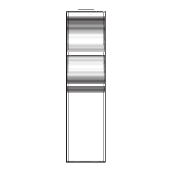
Page 2: How Your Oil-Fired Furnace Works
• Never attempt to light the burner / appliance by throwing burn- ing material into the appliance. DFAA Coil Cabinet • Never attempt to use crankcase or waste oil or material other than the approved fuel oils in this burner. -
Page 3: Owner Service And Maintenance
107273-UUM-C-0306 DAILY Check the room in which your burner / appliance is installed. Make sure: • Installation and adjustment of the burner requires technical and • Air ventilation openings are clean and unobstructed efficient knowledge and the use of combustion test instruments. •... -
Page 4: Furnace User Maintenance
107273-UUM-C-0306 FURNACE USER MAINTENANCE To Turn Off the Appliance: Set the thermostat to lowest setting. Turn off all electric power to the appliance if service is to be per- formed. Remove burner access panel. Before proceeding, be sure the area is well ventilated. Turn the Turn the valve attached to the oil pump to the closed position. -
Page 5: Service And Maintenance Manual
107273-UUM-C-0306 The following safety rules must be followed when servicing the TABLE 1: Filter Sizes furnace. Blower Door Return inches (2) 16 x 20 (2) 41 x 51 CARBON MONOXIDE POISONING HAZARD - Carbon Mon- Blower Care oxide is a colorless, odorless gas than can kill. Follow these rules to control carbon monoxide. -
Page 6: Furnace Maintenance
107273-UUM-C-0306 FURNACE CLEANING • Check the burner performance. Refer to the section “Set combus- tion with instruments.” NOTE: The cleaning operations listed below must be performed only by It is good practice to make a record of the service performed and the a qualified service agency. -
Page 7: Replacing The Oil Pump
107273-UUM-C-0306 23. Reconnect the connector tube assembly and tighten the flare fit- ting. 24. Check the transformer spring contacts. If worn, replace. Use care when removing and installing oil nozzles. 25. Push the transformer up and forward checking to make sure the springs are touching the electrode rods. -
Page 8: Oil Furnace Sequence Of Operation
Heating Cycle Turn off all power to the burner before servicing. When the thermostat switch on a DFAA is set on HEAT and the fan is set on AUTO, (DFAH has no manual fan operation), and there is a call Disconnect the burner motor wires. -
Page 9: Start Up And Safety Check Procedure
107273-UUM-C-0306 BURNER MOTOR-OFF DELAY (Postpurge) - If applicable, the Simulate Ignition Failure: fuel valve is de-energized and the burner motor is kept on for the Follow burner start-up, but do not open oil supply hand valve. selected postpurge time before the control returns to standby. Observe that safety switch locks out approximately within the START UP AND SAFETY CHECK PROCEDURE selected time as indicated on the label. - Page 10 107273-UUM-C-0306 Resetting from Restricted Lockout TABLE 4: Cad Cell Resistance When Sensing Flame If the control locks out three times in a row, without a complete heat Flashes Cad Cell Resistance in Ohms cycle between attempts, the lockout becomes restricted in order to pre- Less than 400 vent repetitious resetting by the homeowner.
- Page 11 107273-UUM-C-0306 TABLE 5: Oil Burner Operation EXTERNAL ACTION R7184 PRIMARY CONTROL ACTION Internal safety check conducted. If no light or flame is detected and all internal conditions are correct, con- Power applied to control trol enters Idle Mode. Shorts across T - T terminals (on a call for heat) in warm air system and/or provides power to limit ter- minals.
- Page 12 107273-UUM-C-0306 TABLE 6: Oil Burner Control Troubleshooting PROCEDURE STATUS CORRECTIVE ACTIONS Check that limit switches are — — closed and contacts are clean. Check for line voltage power at the oil primary control. Voltage should — — be 120 VAC Check indicator light with burner Cad cell or controller is defective, sees external light or connections are shorted.
- Page 13 107273-UUM-C-0306 TABLE 6: Oil Burner Control Troubleshooting (Continued) PROCEDURE STATUS CORRECTIVE ACTIONS Listen for spark after burner turns Spark ignitor could be defective. Check for line voltage at ignitor terminals. If line Ignition is off. on (after a 2-second delay). voltage is present, replace R7184.
-
Page 14: Wiring Diagram - Oil-Fired Furnace
107273-UUM-C-0306 SECTION III: WIRING DIAGRAM - OIL-FIRED FURNACE FIGURE 13: Wiring Diagram for DFAA - Oil-Fired Furnace Unitary Products Group... - Page 15 107273-UUM-C-0306 FIGURE 14: Wiring Diagram for DFAH - Oil-Fired Furnace Unitary Products Group...
-
Page 16: Gas Conversion Burner
107273-UUM-C-0306 SECTION IV: GAS CONVERSION BURNER CARBON MONOXIDE POISONING HAZARD - Carbon Mon- oxide is a colorless, odorless gas than can kill. Follow these FIRE OR EXPLOSION HAZARD - Failure to follow safety rules to control carbon monoxide. warnings exactly could result in serious injury, death, or prop- erty damage. -
Page 17: Instructions For Examining The Furnace
Terminals on Primary Control Primary Control Gas Orifice Spud Junction Box 3. Remove Filter Door to Examine Burner DFAA A/C Coil Cabinet Combustion Air Pipe Motor 7. Remove Burner Door to Examine Burner Flame FIGURE 15: Component Locations INSTRUCTIONS FOR EXAMINING THE FURNACE 4. -
Page 18: Start-Up And Shutdown Instructions
107273-UUM-C-0306 Your Service Technician Turn off all electric power to the appliance. Remove furnace door. Your furnace's best friend is your qualified service technician. If the unit gives any indication of improper operation, call your service technician. Move gas control switch to the “OFF” position. Do not force. See If the service technician is allowed to perform the normal routine care of Figure 18. -
Page 19: Furnace User Maintenance
107273-UUM-C-0306 FURNACE USER MAINTENANCE Blower Care Even with good filters properly in place, blower wheels and motors will become dust laden after long months of operation. The entire blower assembly should be inspected annually. If the motor and wheel are heavily coated with dust, they can be brushed and cleaned with a vac- Before proceeding, be sure the area is well ventilated. -
Page 20: Service And Maintenance Manual
107273-UUM-C-0306 SECTION V: SERVICE AND MAINTENANCE Cleaning the Heat Exchanger MANUAL NOTE: It is recommended that replacement gaskets be available SAFETY SECTION before removing vent motor. Lower Heat Exchanger Access This section has been designed to assist a qualified service agency in Turn off the electrical power to the unit and turn off gas supply at performing service and maintenance on this appliance. -
Page 21: Wiring Diagram - Gas Conversion Burner
107273-UUM-C-0306 SECTION VI: WIRING DIAGRAM - GAS CONVERSION BURNER FIGURE 20: Wiring Diagram for DFAA - Gas Conversion Burner Unitary Products Group... - Page 22 107273-UUM-C-0306 FIGURE 21: Wiring Diagram for DFAH - Gas Conversion Burner Unitary Products Group...
-
Page 23: Honeywell S87K Primary Ignition Control Troubleshooting Guide
107273-UUM-C-0306 HONEYWELL S87K PRIMARY IGNITION CONTROL TROUBLESHOOTING GUIDE MOTOR DOES NOT RUN 1. CHECK THE LOW VOLTAGE TRANSFORMER FOR REPLACE 24 VAC CHECK ELECTRICAL WIRING 24 VOLT OUTPUT BETWEEN TERMINAL 3 ON THE 20 VA TRANSFORMER AND CONNECTIONS MOTOR START RELAY AND EITHER OF THE “T” TERMINALS ON THE CONTROL BOX 2. - Page 24 107273-UUM-C-0306 NO IGNITION ARC ESTABLISHED 1. RESET CONTROL: - MOTOR STARTS - COMPLETES 30 SECOND PREPURGE CYCLE, 8 SECOND SAFE START CHECK SERIES - GAS VALVE OPENS, REGULATING ADEQUATE GAS PRESSURE. - NO FLAME ESTABLISHED - PRIMARY CONTROL LOCKS OUT AFTER 4 SECOND HONEYWELL SERIES TRIAL FOR IGNITION PERIODS IN ORDER FOR THE FOLLOWING FUNCTIONAL TEST TO BE MADE, THE CONTROL MUST BE RESET AND THE TESTS MONITORED DURING THE 4 SECOND HONEYWELL SERIES TRIAL FOR IGNITION THAT OCCURS AT THE END OF THE...
- Page 25 107273-UUM-C-0306 LOSES FLAME DURING CYCLE - CONTROL LOCKS OUT ON SAFETY 1. RESET CONTROL: - COMPLETES 30 SECOND PREPURGE CYCLE, AND 8 SECOND SAFE START CHECK - FLAME IS ESTABLISHED - SOMETIMES THE CONTROL LOCKS OUT BEFORE THE THERMOSTAT OR CONTROLLING CIRCUIT IS SATISFIED PROBABLE CAUSE OF ERRATIC LOCKOUT: 2.
-
Page 26: Oil Burner Repair Parts List
107273-UUM-C-0306 SECTION VII: OIL BURNER REPAIR PARTS LIST HEAT/COOL (DFAA) DFAA066BBTA DFAH066BBSA DFAA084BBTA DFAH084BBSA HEAT ONLY (DFAH) CONTROL BOX DETAIL Unitary Products Group... -
Page 27: Replacement Part Contact Information
107273-UUM-C-0306 DFAH DFAA FIG ITEM DESCRIPTION DFAH066BBSA DFAH084BBSA FIG ITEM DESCRIPTION DFAA066BBTA DFAA084BBTA Limit Switch, Manual (Upper) 025-35358-000 025-35358-000 Limit Switch, Manual (Upper) 025-35358-000 025-35358-000 Thermostat (Heat Only) 025-38746-000 025-38746-000 Thermostat (Heat /Cool) 025-38746-000 025-38746-000 Exchanger, Heat (w/Gaskets) 373-19806-651 373-19806-651... - Page 28 107273-UUM-C-0306 OIL BURNER ASSEMBLY 026-37356-000 026-37357-000 ITEM DESCRIPTION PART NO. Burner Housing Assembly 026-39203-000 026-39203-000 Air Boot Kit 026-39204-000 026-39204-000 Inlet Air Hose 026-39205-000 026-39205-000 Hose Clamps (2 Req’d) 026-39206-000 026-39206-000 Escutcheion Plate 026-39207-000 026-39207-000 Hole Plug (Included as part of Housing, Item #1) 026-39226-000 026-39226-000 Air Inlet Bell (Factory Installed, Do Not Remove from Burner)
-
Page 29: Gas Conversion Burner Repair Parts List
107273-UUM-C-0306 SECTION VIII: GAS CONVERSION BURNER REPAIR PARTS LIST BURNER MODELS: SC80-C MINIMUM INPUT: 66,000 BTU/HR MAXIMUM INPUT: 84,000 BTU/HR ELECTRICAL POWER SUPPLY: 115V/60HZ 1 FUELS: NATURAL & L.P. GAS @ 3.5” W.C. MOUNTING: FIXED FLANGE Unitary Products Group... - Page 30 107273-UUM-C-0306 PARTS LIST ITEM PART NUMBER DESCRIPTION TYPE 63879-001 WELDMENT, BURNER TUBE - PAINTED 63610-001 ASSEMBLY, VENTURI - SC80 YORK 63620-001 GASKET, END CAP 60172-002 MOTOR/BLOWER ASSEMBLY 115V / 50 - 60 HZ 63617-001 MANIFOLD, SC80 / 200 / SC200M 12697-002 SCREW, HXSLT 23 10 - 24 X .375 15766...
- Page 31 107273-UUM-C-0306 NOTES Unitary Products Group...
-
Page 32: Limited Warranty
If there is no distributor in your area, and you cannot obtain proper service under the terms of the warranty, please write: Unitary Products Group (UPG) Customer Relations Department, PO Box 19014, Wichita, KS 67204-9014. Subject to change without notice. Printed in U.S.A. 107273-UUM-C-0306 Copyright © by York International Corp. 2006. All rights reserved. Supersedes: 107273-UUM-B-1105 Unitary 5005...
Need help?
Do you have a question about the DFAA and is the answer not in the manual?
Questions and answers