Table of Contents
Advertisement
INSTALLATION
INSTRUCTION
TABLE OF CONTENTS
FURNACE SPECIFICATIONS . . . . . . . . . . . . . . . . .2
GENERAL INFORMATION . . . . . . . . . . . . . . . . . . . .3
INSTALLATION STANDARDS . . . . . . . . . . . . . . . . .3
CODE COMPLIANCE . . . . . . . . . . . . . . . . . . . . . .3
HIGH ALTITUDE INSTALLATION . . . . . . . . . . . .3
MINIMUM FURNACE CLEARANCES . . . . . . . . .3
RETURN AIR REQUIREMENTS . . . . . . . . . . . . . . . .4
CLOSET INSTALLATIONS . . . . . . . . . . . . . . . . . .4
AIR DISTRIBUTION SYSTEMS . . . . . . . . . . . . . .4
ROOF JACK . . . . . . . . . . . . . . . . . . . . . . . . . . . . . . .6
EXISTING FURNACE REPLACEMENT . . . . . . . .6
NEW HOME INSTALLATION . . . . . . . . . . . . . . . .6
INSTALLATION IN SNOW REGIONS . . . . . . . . .6
OPENING . . . . . . . . . . . . . . . . . . . . . . . . . . . . . . .6
INSTALLING ROOF JACK IN ROOF . . . . . . . . . .6
DUCT CONNECTORS . . . . . . . . . . . . . . . . . . . . . . .9
DUCT CONNECTOR . . . . . . . . . . . . . . . . . . . . .10
DUCT CONNECTORS . . . . . . . . . . . . . . . . . . . .10
INSTALLATION OF THE FURNACE . . . . . . . . . . .11
CEILING RINGS . . . . . . . . . . . . . . . . . . . . . . . . .12
ELECTRICAL WIRING . . . . . . . . . . . . . . . . . . . . . .12
CONNECT POWER SUPPLY WIRES . . . . . . . .12
CONNECT THERMOSTAT WIRES . . . . . . . . . .12
WALL THERMOSTAT . . . . . . . . . . . . . . . . . . . . .13
WIRING DIAGRAMS . . . . . . . . . . . . . . . . . . . . . . .14
GAS PIPING . . . . . . . . . . . . . . . . . . . . . . . . . . . . . .19
HIGH ALTITUDE DERATION CHART . . . . . . . .21
REPAIR PARTS LIST . . . . . . . . . . . . . . . . . . . . . . .22
CAUTION: READ ALL SAFETY GUIDES BEFORE
YOU START TO INSTALL YOUR UNIT.
SAVE THIS MANUAL
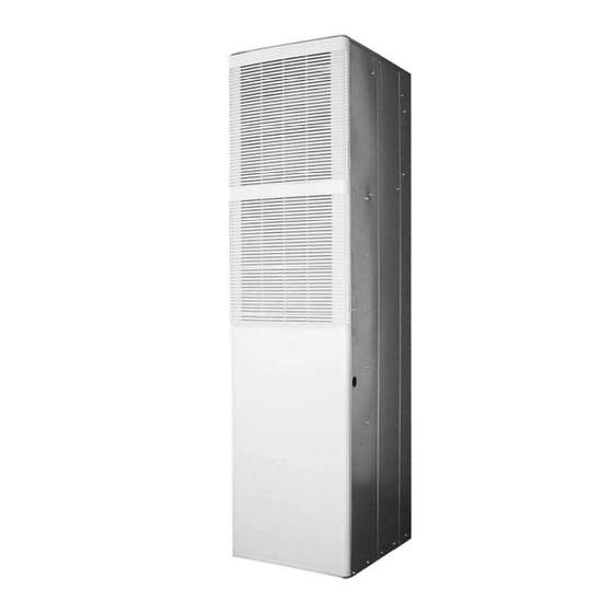
SEALED COMBUSTION
DOWNFLOW GAS FURNACE
MODELS: DGAA, DGAH, DGPA, AND DGPH
For Installation In:
1.
Manufactured (Mobile) Homes
2.
Recreational Vehicles & Park Models
3.
Modular Homes & Buildings
IMPORTANT - Only individuals having proven experience with this
type of equipment should attempt to perform set-up.
Proper furnace set-up and adjustment is the responsibility of the
retailer/homeowner and is not covered under warranty.
FURNACE START-UP CHECK LIST
•
Has roof jack crown been correctly installed?
•
Has furnace gas valve and burner orifice been correctly con-
verted for Propane. gas where applicable?
•
Has furnace gas valve been de-rated for altitudes above 2000
feet where applicable?
•
Is gas line outlet pressure properly set for fuel type? (natural gas
is 3.5" W.C.; Propane is 10" W.C.)
•
Is cross-over duct installed per home builder and UPG installa-
tion instructions?
•
Has furnace been operated through a complete heating cycle?
•
Has the pilot flame been adjusted properly? (DGPH and DGPA
Models)
035-16328-002 Rev. C (0902)
Advertisement
Table of Contents

Subscribe to Our Youtube Channel
Related Manuals for York International DGAA


Summary of Contents for York International DGAA
-
Page 1: Table Of Contents
SEALED COMBUSTION DOWNFLOW GAS FURNACE INSTRUCTION MODELS: DGAA, DGAH, DGPA, AND DGPH TABLE OF CONTENTS FURNACE SPECIFICATIONS ....2 GENERAL INFORMATION ....3 INSTALLATION STANDARDS . -
Page 2: Furnace Specifications
035-16328-002 Rev. C (0902) FURNACE SPECIFICATIONS DGAA — AUTOMATIC IGNITION — WITH BUILT-IN COIL CABINET — 4 TON - A/C READY MODEL NO. Factory Equipped for use with Input/BTUH Output/BTUH DGAA056BDTA NATURAL GAS 56,000 45,000 DGAA070BDTA NATURAL GAS 70,000 56,000... -
Page 3: General Information
035-16328-002 Rev. C (0902) GENERAL INFORMATION Recreational Vehicles in U.S.A.: Standard on Recreational Vehicles (NFPA 1192, formerly NOTE: The words “Shall" or “Must" indicate a requirement NFPA 501C). which is essential to satisfactory and safe product perfor- National Electrical Code (NFPA 70). mance. -
Page 4: Return Air Requirements
035-16328-002 Rev. C (0902) RETURN AIR REQUIREMENTS Non-combustible pans having one-inch upturned flanges are located beneath openings in the floor return duct CLOSET INSTALLATIONS system. Wiring materials located in the return duct system con- Additional Requirements form to Article 300-22 (B&C) of the National Electrical Additional requirements for floor and ceiling return system for Code (NFPA-70). - Page 5 035-16328-002 Rev. C (0902) Furnace to Closet Door Clearance — 5 Inches or more The closet door MUST have a minimum of 250 Square Inches Return Air Grille Part No. 7900-287P/A * White of free area in the upper half of the door. If opening for return air is located in the floor or sidewalls and below the top of the furnace casing: 1.
-
Page 6: Roof Jack
035-16328-002 Rev. C (0902) ROOF JACK NEW HOME INSTALLATION If this furnace is installed on a new home do the following: Inspect the furnace top collars for signs of insulation or ceiling debris which might have fallen in during cutting of the ceiling and roof holes. - Page 7 035-16328-002 Rev. C (0902) DGAH FURNACES DGPH, DGPA, & DGAA FURNACES SWIVEL FLASHING SLANT INSTALLATION DIMENSIONS INSTALLATION DIMENSIONS ADJUSTS FROM FLASHING 0/12 TO 5/12 PITCH 3/12 PITCH “A” “B” ADJUSTABLE HEIGHT ADJUSTABLE HEIGHT 4000-7101/C 4000-6101/A 70” to 79” 86” to 95”...
- Page 8 035-16328-002 Rev. C (0902) DGAH FURNACES DGPH, DGPA, & DGAA FURNACES SWIVEL FLASHING SLANT INSTALLATION DIMENSIONS INSTALLATION DIMENSIONS ADJUSTS FROM FLASHING 0/12 TO 5/12 PITCH 3/12 PITCH “B” “A” ADJUSTABLE HEIGHT ADJUSTABLE HEIGHT 4000-8161/C 4000-9161/A 85” to 101” 101” to 117”...
-
Page 9: Duct Connectors
035-16328-002 Rev. C (0902) DUCT CONNECTORS 2 3 8 2 3 8 2 3 8 2 3 8 2 3 8 2 3 8 2 3 8 2 3 8 CHART CHART 2 3 8 2 3 8 2 3 8 2 3 8 18 3 4 4 3 8... -
Page 10: Installation Of Screw Attachment Duct Connector
035-16328-002 Rev. C (0902) LOCATOR BRACKET LOCATOR BRACKET NAILS, FLAT HEAD SCREWS NAILS, FLAT HEAD SCREWS OR STAPLES OR STAPLES BEND TABS UNDER DUCT OPENING TO SCREWS SECURE TO THE SUPPLY DUCT. FLOOR FLOOR SUPPLY DUCT SUPPLY DUCT Duct Connector Screw Attachment Duct Connector Tab Attachment FIGURE 11 : FIGURE 12 :... -
Page 11: Installation Of The Furnace
035-16328-002 Rev. C (0902) The inner flue pipe must be present. FURNACE SEATED It is mandatory that the combustion air pipe and AGAINST THE LOCATOR BRACKET flue pipe assembly be fully engaged. The com- bustion air pipe MUST be securely fastened to SECURE FURNACE TO FLOOR WITH the furnace with a sheet metal screw in the hole... -
Page 12: Ceiling Rings
035-16328-002 Rev. C (0902) CEILING RINGS CONNECT THERMOSTAT WIRES The ceiling ring is to meet fire stop requirements. Accessory Insert 24 volt wires through the small plastic bushing just Ceiling Ring (P/N 7660-2841) may be used, (See Figure 15) above the control panel. or the manufactured home manufacturer or the installer may Connect the thermostat wires to the furnace low voltage use other approved methods to stop fire. -
Page 13: Wall Thermostat
035-16328-002 Rev. C (0902) WALL THERMOSTAT Avoid locations where the thermostat could be subject to drafts from outside, or exposed to direct light from lamps, sun, fireplaces, etc., or affected by air from a duct register blowing directly on the thermostat. FURNACE CONTROL The wall thermostat should be located 52 to 66 inches above... -
Page 14: Wiring Diagrams
035-16328-002 Rev. C (0902) WIRING DIAGRAMS BLOWER MOTOR SCREW TRANSFORMER LOAD 24V SEC. SWITCH 120V PRI. MANUAL RESET LIMIT SWITCH LINE AUTO 3 AMP FUSE RESET LIMIT SWITCH SYSTEM SWITCH NEU. CONTROL 115 VAC GND. WALL SCREW TO EARTH GND. THERMOSTAT Wiring Diagram for DGPH056, DGPH070, DGPH077 FIGURE 19 :... - Page 15 035-16328-002 Rev. C (0902) COMBUSTION BLOWER BLOWER MOTOR RELAY GND. SCREW TRANSFORMER LOAD 24V SEC. SWITCH 120V PRI. MANUAL RESET LIMIT SWITCH LINE AUTO RESET 3 AMP FUSE LIMIT SWITCH SYSTEM PRESSURE SWITCH SWITCH NEU. 115 VAC GND. WALL SCREW THERMOSTAT TO EARTH GND.
- Page 16 035-16328-002 Rev. C (0902) FIGURE 21 : Unitary Products Group...
- Page 17 035-16328-002 Rev. C (0902) BLOWER MOTOR COMBUSTION BLOWER RELAY BLOWER GND. RELAY SCREW SWITCH MANUAL TRANSFORMER BLEND AIR RESET LOAD CONTROL BOX LIMIT (IF EQUIPPED) SWITCH 24V SEC. 120V PRI. LINE AUTO RESET 3 AMP FUSE LIMIT SWITCH CONDENSING UNIT PRESSURE CONTACTOR SYSTEM...
- Page 18 SWITCH COMBUSTION AIR SWITCH WALL THERMOSTAT TO A/C CONDENSING UNIT (if equipped) BLOWER MOTOR TRANSFORMER GROUND TO EARTH GROUND SCREW SYSTEM VALVE SWITCH NEUTRAL HOT SURFACE IGNITOR Wiring Diagram for DGAA and DGAH Models FIGURE 23 : Unitary Products Group...
-
Page 19: Gas Piping
035-16328-002 Rev. C (0902) GAS PIPING For natural gas operation, the furnace is designed for 7" W.C. inlet gas pressure. Pressure to main burner is then reduced INSTALLATION AND CHECKING OF GAS LINE to 3 1/2" W.C. Gas Supply piping must be sized in accordance with the rec- For Propane gas operation, the furnace is designed for 11"... - Page 20 035-16328-002 Rev. C (0902) FINAL PROCEDURE FURNACE AND AIR CONDITIONER INSTALLATIONS INSTALL FURNACE DOORS If an air conditioner is installed which does not use the blower Install the lower door first by sliding the bottom of the door for air distribution and operates completely independent of down until the tabs on the casing base engage the slots in the the furnace, the thermostat system must have an interlock to bottom door end cap.
-
Page 21: High Altitude Deration Chart
035-16328-002 Rev. C (0902) HIGH ALTITUDE DERATION CHART NATURAL GAS 56,000 — Input 70,000 — Input 77,000 — Input 90,000 — Input Elevation Orifice Drill Orifice Drill Orifice Drill Orifice Drill Part # Part # Part # Part # Dia. Size Dia. -
Page 22: Repair Parts List
035-16328-002 Rev. C (0902) REPAIR PARTS LIST Unitary Products Group... - Page 23 2. For Serial Numbers lower then 001207164- Replacement DGAA motors also require Motor Mount Assembly 373-19806-100 if replaced motor has integral, flex-arm motor mount. 3. DGAA with 5-Ton Blowers are provided as an accessory item and are not standard equipment from the factory. See Page 6...
- Page 24 035-16328-002 Rev. C (0902) DGAH ITEM DESCRIPTION DGAH056BBSA DGAH077BBSA Switch, Pressure 024-27666-000 024-27666-000 Tubing Silicone (2’ Req’d) 028-11957-000 028-11957-000 025-35358-000 025-35358-000 Limit Switch, Manual (Upper) Assembly, Booster (w/Motor) 373-19801-820 373-19801-820 Control Board, Integrated 031-01932-000 031-01932-000 Valve, Gas 7990-328P 7990-328P Bracket, Valve 073-19801-064 073-19801-064 Thermostat (Heat /Cool)
- Page 25 035-16328-002 Rev. C (0902) DGPA ITEM DESCRIPTION DGPA056ABTA DGPA070ABTA DGPA077ABTA DGPA090ABTA Switch, Pressure 024-27666-000 Tubing Silicone (2’ Req’d) 028-11957-000 025-35358-000 025-35358-000 025-35358-000 025-35358-000 Limit Switch, Manual (Upper) Assembly, Booster (w/Motor) 373-19801-820 Control Board, Integrated Valve, Gas 7956-336P 7956-336P 7956-336P 7956-336P Bracket, Valve 073-19801-064 073-19801-064...
- Page 26 035-16328-002 Rev. C (0902) DGPH ITEM DESCRIPTION DGPH056ABTA DGPH070ABTA DGPH077ABTA DGPH090ABTA Switch, Pressure 024-27666-000 Tubing Silicone (2’ Req’d) 028-11957-000 025-35358-000 025-35358-000 025-35358-000 025-35358-000 Limit Switch, Manual (Upper) Assembly, Booster (w/Motor) 373-19801-820 Control Board, Integrated Valve, Gas 7956-336P 7956-336P 7956-336P 7956-336P Bracket, Valve 073-19801-064 073-19801-064...
- Page 27 9951-0981 9951-1061 NOTES 4. Contact Customer Service for installations at altitudes over 2000 feet above sea level. “<“ Across from row indicates a change in that row. ACCESSORY PARTS LIST DESCRIPTION DGAA DGAH DGPA DGPH Thermostat (Heat/Cool) 025-38251-000 025-38251-000 025-38251-000 <...
- Page 28 NOTES Subject to change without notice. Printed in U.S.A. 035-16328-002 Rev. C (0902) Copyright © by York International Corp. 2002. All rights reserved. Supersedes: 0035-16328-002 Rev. B (1001) Unitary P.O. Wichita Products Group 19014 67204-9014...
Need help?
Do you have a question about the DGAA and is the answer not in the manual?
Questions and answers