KTM 2011 990 Supermoto T USA Owner's Manual
Hide thumbs
Also See for 2011 990 Supermoto T USA:
- Owner's manual (218 pages) ,
- Owner's manual (208 pages)
Table of Contents
Advertisement
Quick Links
Advertisement
Table of Contents

Related Manuals for KTM 2011 990 Supermoto T USA


Summary of Contents for KTM 2011 990 Supermoto T USA
- Page 1 OWNER'S MANUAL 2011 990 Supermoto T USA Art. no. 3211663en...
- Page 3 DEAR KTM CUSTOMER We would like to congratulate you on deciding to purchase a KTM motorcycle. You are now the owner of a state-of-the-art sports motorcy- DEAR KTM CUSTOMER cle that will give you enormous pleasure if you service and maintain it accordingly.
- Page 4 DEAR KTM CUSTOMER ISO 9001(12 100 6061) According to the international quality management standard ISO 9001, KTM uses quality assurance processes that lead to the maximum possible quality of the products. Issued by: TÜV Management Service KTM-Sportmotorcycle AG 5230 Mattighofen, Austria...
-
Page 5: Table Of Contents
TABLE OF CONTENTS Combination instrument - indicator lamps......37 TABLE OF CONTENTS MEANS OF REPRESENTATION ..........7 Combination instrument - display........38 IMPORTANT INFORMATION ........... 8 Combination instrument - speedometer....... 39 Overview of labels............. 12 Setting kilometers or miles ..........39 VIEW OF VEHICLE.............. - Page 6 TABLE OF CONTENTS Running in the engine............54 Taking the motorcycle off of the rear wheel stand ....82 Loading the vehicle ............54 Bleeding the fork legs ............83 RIDING INSTRUCTIONS ............57 Removing the seat ............83 Checks and maintenance measures when preparing for Mounting the seat ............
- Page 7 TABLE OF CONTENTS Checking the rear brake linings ........109 Draining the coolant ..........157 WHEELS, TIRES ..............111 Filling/bleeding the cooling system ......158 Removing the front wheel ........... 111 TUNING THE ENGINE ............161 Installing the front wheel ..........
- Page 8 TABLE OF CONTENTS TECHNICAL DATA - ENGINE TIGHTENING TORQUES... 191 TECHNICAL DATA - CHASSIS ..........194 Lighting equipment ............195 Tires ................196 Capacity - fuel..............196 TECHNICAL DATA - FORK........... 197 TECHNICAL DATA - SHOCK ABSORBER ......199 TECHNICAL DATA - CHASSIS TIGHTENING TORQUES ..201 SUBSTANCES..............
-
Page 9: Means Of Representation
All work marked with this symbol requires specialist knowledge and technical understanding. In the interest of your own safety, have these jobs performed by an authorized KTM workshop! There, your motorcycle will be serviced opti- mally by specially trained experts using the specialist tools required. -
Page 10: Important Information
The work prescribed in the service schedule must be carried out by an authorized KTM workshop only and confirmed in the customer's service record and in the KTM dealer.net; otherwise, all warranty claims will be void. No warranty claim can be honored for damage result- ing from manipulation and/or other changes to the vehicle. - Page 11 Spare parts, accessories For your own safety, only use spare parts and accessory products that have been approved and/or recommended by KTM and have them installed by an authorized KTM workshop. KTM accepts no liability for other products and any resulting damage.
- Page 12 IMPORTANT INFORMATION – Switch off the engine and remove the ignition key. – Secure the motorcycle against falling over or rolling away using straps or other suitable devices. Environment Motorcycling is a wonderful sport and we naturally hope that you can enjoy it to the full. However, it can also lead to problems with the environment and conflict with other persons.
-
Page 14: Overview Of Labels
IMPORTANT INFORMATION Overview of labels B00691-10... - Page 15 IMPORTANT INFORMATION Information on emission control Type label, Canada Information on operating substances and tires Information on noise emission Information on preparing for use Information on the fuel evaporation system Information on chain tension Information on suspension setting Type label, USA B00692-01 Information on emission control...
- Page 16 IMPORTANT INFORMATION B00693-01 Type label, Canada B00694-01 Information on operating substances and tires...
- Page 17 IMPORTANT INFORMATION B00695-01 Information on noise emission Information on preparing for use 600961-01...
- Page 18 IMPORTANT INFORMATION B00696-01 Information on the fuel evaporation system Information on chain tension 600966-01...
- Page 19 IMPORTANT INFORMATION Information on suspension setting B00697-01 B00698-01 Type label, USA Notes/warnings Pay close attention to the notes/warnings. Info Various information and warning labels are affixed to the vehicle. Do not remove information/warning labels. If they are missing, you or others may not recognize potential hazards and may therefore be injured.
- Page 20 If NHTSA receives similar complaints, it may open an investigation. If it finds that a safety defect exists in a group of vehicles, it may order a recall and remedy campaign. However, NHTSA cannot become involved in individual problems between you, your dealer, or KTM...
- Page 21 Noise emission warranty KTM Sportmotorcycle AG warrants that this exhaust system, at the time of sale, meets all applicable U.S. EPA Federal noise standards. This warranty extends to the first person who buys this exhaust system for purposes other than resale, and to all subsequent buyers.
- Page 22 Consumer rights Warranty claims should be submitted to an authorized KTM workshop. If you are not satisfied, please contact: KTM North America, Inc., Customer Support, 1119 Milan Ave., Amherst, OH 44001, USA Phone: (440) 985–3553...
-
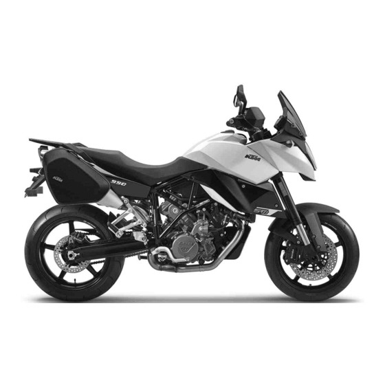
Page 24: View Of Vehicle
VIEW OF VEHICLE View of vehicle, front left side (vehicle differs slightly from photo) B00690-10... - Page 25 VIEW OF VEHICLE Combination instrument ( p. 35) Rear mirror Clutch lever ( p. 30) Seat Handrails ( p. 48) Level viewer, engine oil Shift lever ( p. 51) Engine number ( p. 28) Compression damping of the shock absorber ( p.
-
Page 26: View Of Vehicle, Rear Right Side (Vehicle Differs Slightly From Photo)
VIEW OF VEHICLE View of vehicle, rear right side (vehicle differs slightly from photo) B00689-10... - Page 27 VIEW OF VEHICLE Seat lock ( p. 49) Light switch ( p. 31) Headlight flasher switch ( p. 32) Turn signal switch ( p. 32) Horn button ( p. 33) Filler cap Emergency OFF switch ( p. 34) Electric starter button ( p.
-
Page 28: Serial Numbers
SERIAL NUMBERS Chassis number/type label The chassis number is stamped on the frame behind the steering head on the right. B00664-10 The type label for the USA is fitted on the frame tube on the right. 601116-10... -
Page 29: Key Number
SERIAL NUMBERS The type label for Canada is fitted on the frame tube on the left. 601115-10 Key number The Code number key number can be found on the KEYCODECARD. Info You need the key number to order a spare key. Keep the KEYCODECARD in a safe place. -
Page 30: Engine Number
SERIAL NUMBERS Engine number The engine number is stamped on the left side of the engine under the engine sprocket. B00120-10 Fork part number The fork part number is stamped on the inner side of the fork stub. B00606-10... -
Page 31: Shock Absorber Part Number
SERIAL NUMBERS Shock absorber part number The shock absorber part number is stamped on the top of the shock absorber above the adjusting ring on the engine side. B00607-10... -
Page 32: Controls
CONTROLS Clutch lever The clutch lever is fitted on the left side of the handlebar. The clutch is hydraulically operated and self-adjusting. B00608-10 Hand brake lever The hand brake lever is fitted on the right side of the handlebar. ... -
Page 33: Throttle Grip
CONTROLS Throttle grip The throttle grip is fitted on the right side of the handlebar. B00655-10 Light switch The light switch is fitted on the left side of the handlebar. Possible states Low beam on – The light switch is turned downwards. In this position, the low beam and tail light are switched on. -
Page 34: Headlight Flasher Switch
CONTROLS Headlight flasher switch The headlight flasher switch is fitted on the left side of the handlebar. Possible states • Headlight flasher switch in basic position Headlight flasher switch pressed – The headlight flasher switch (high beam) is oper- •... -
Page 35: Horn Button
CONTROLS Horn button The horn button is fitted on the left side of the handlebar. Possible states • Horn button in basic position pressed – The horn is operated in this position. • Horn button B00656-12 Ignition/steering lock The ignition/steering lock is in front of the upper triple clamp. Info The ignition may only be switched on using a black ignition key. -
Page 36: Immobilizer
The second black ignition key is activated when the vehicle is shipped. Two additional spare ignition keys (key number on the KEYCODECARD) can be ordered from an authorized KTM workshop, but they must be activated before use. Emergency OFF switch 5.10... -
Page 37: Electric Starter Button
CONTROLS Electric starter button 5.11 The electric starter button is fitted on the right side of the handlebar. Possible states • Electric starter button in basic position pressed – The electric starter is actuated in this position. • Electric starter button B00657-11 Combination instrument 5.12... -
Page 38: Combination Instrument - Function Buttons
CONTROLS Combination instrument - function buttons 5.13 You can change the display mode with the MODE button Possible display modes are the distance traveled (ODO), trip master 1 (TRIP 1), trip mas- ter 2 (TRIP 2), and the ambient temperature. Press the SET button to reset the trip master 1 function (TRIP 1) and trip master 2 func- ... -
Page 39: Combination Instrument - Indicator Lamps
CONTROLS Combination instrument - indicator lamps 5.15 The indicator lamps offer additional information about the operating state of the motorcy- cle. Possible states The turn signal indicator light flashes green simultaneously with the turn signal – The turn signal is switched on. The idling speed indicator lamp lights up green –... -
Page 40: Combination Instrument - Display
CONTROLS Combination instrument - display 5.16 When you switch on the ignition, all display segments light up for one second as a function test. 400892-01 LEnGth Following the display function test, the LEnGth wheel circumference is shown for one sec- ond. -
Page 41: Combination Instrument - Speedometer
CONTROLS Combination instrument - speedometer 5.17 The speed is shown in kilometers per hour km/h or in miles per hour mph. 400838-10 Setting kilometers or miles 5.18 Info If you change the unit, the value ODO is retained and converted accordingly. Making the setting according to the country. -
Page 42: Combination Instrument - Time
CONTROLS – Switch on the ignition by turning the ignition key to the ON position. – Press the MODE button repeatedly until the ODO mode is active. – Keep the MODE button pressed until the display mode changes from km/h to mph or from mph to km/h. -
Page 43: Combination Instrument - Odo Display
CONTROLS – Switch on the ignition by turning the ignition key to the ON position. – Press the MODE button repeatedly until the ODO mode is active. – Keep the MODE button and the SET button pressed simultaneously. The time display begins to flash. –... -
Page 44: Combination Instrument - Setting/Resetting Trip 2
CONTROLS – Switch on the ignition by turning the ignition key to the ON position. – Press the MODE button repeatedly until the TRIP 1 mode is active. – Keep the SET button pressed. The TRIP 1 display is set to 0.0. 400840-01 Combination instrument - setting/resetting TRIP 2 5.23... -
Page 45: Combination Instrument - Trip F Display
CONTROLS Combination instrument - TRIP F display 5.24 If the fuel level drops to the reserve mark, the display automatically changes to TRIP F and starts to count from 0.0, regardless of the previous display mode. Info The low fuel warning lamp lights up in parallel to the TRIP F display. 400842-01 Combination instrument - ambient temperature display 5.25... -
Page 46: Setting The Temperature Units
CONTROLS Setting the temperature units 5.26 Condition The motorcycle is stationary. – Switch on the ignition by turning the ignition key to the ON position. – Press the MODE button repeatedly until the ambient temperature is active. – Keep the MODE button pressed until the display mode changes from °C to °F or from °F to °C. -
Page 47: Combination Instrument - Coolant Temperature Indicator
CONTROLS Combination instrument - coolant temperature indicator 5.28 The temperature display consists of 12 bars. The more bars that light up, the hotter the coolant. When the upper bar lights up, all bars in the display begin to flash and the temper- ature warning lamp lights up. -
Page 48: Socket For Electrical Accessories
CONTROLS Socket for electrical accessories 5.30 Socket for electrical accessories is fitted next to the ignition/steering wheel lock on the left. It is connected to the battery without an additional switch. Socket for electrical accessories Voltage 12 V Maximum current con- 10 A sumption B00614-10... -
Page 49: Closing The Filler Cap
CONTROLS Warning Environmental hazard Improper handling of fuel is a danger to the environment. – Do not allow fuel to get into the ground water, the ground, or the sewage system. – Lift the cover of the filler cap and insert the ignition key. ... -
Page 50: Handrails
CONTROLS Handrails 5.33 The handrails are used for moving the motorcycle around. If you carry a passenger, the passenger can hold onto the handrails during the trip. 600923-10 Luggage rack plate 5.34 The luggage rack plate is located behind the seat. ... -
Page 51: Seat Lock
CONTROLS Seat lock 5.35 Seat lock is located at the rear under the tail light. It can be locked with the ignition key. 600922-10 Tool set 5.36 The tool set is located in the storage compartment under the seat. ... -
Page 52: Helmet Lock
CONTROLS Helmet lock 5.37 Warning Danger of accidents Impairment of ride behavior and vehicle operation if a helmet or helmet lock is attached to the vehicle. – Do not use the helmet lock for holding a helmet or other objects during the jour- ney. -
Page 53: Shift Lever
CONTROLS Shift lever 5.39 Shift lever is mounted on the left side of the engine. B00120-11 The gear positions can be seen in the photograph. The neutral or idle position is between the first and second gear. B00121-10... -
Page 54: Foot Brake Lever
CONTROLS Foot brake lever 5.40 Foot brake lever is located in front of the right footrest. The rear brake is activated using the foot brake lever. B00122-10 Side stand 5.41 The side stand is located on the left side of the vehicle. ... -
Page 55: Preparing For Use
The front and rear wheels must be fitted with tires with similar tread patterns to prevent loss of control over the vehicle. Warning Danger of accidents Uncontrollable handling characteristic due to non-approved and/or non-recommended tires/wheels. – Only tires/wheels approved by KTM and with the corresponding speed index should be used. Warning Danger of accidents Reduced road grip with new tires. –... -
Page 56: Running In The Engine
PREPARING FOR USE – Make sure that the pre-delivery inspection work has been carried out by an authorized KTM workshop. You receive a delivery certificate and the service record at vehicle handover. – Before your first trip, read the entire operating instructions carefully. - Page 57 PREPARING FOR USE Warning Danger of accidents Unstable handling characteristics due to incorrect mounting of suitcase and/or tank rucksack. – Mount and secure suitcase and tank rucksack according to the manufacturer's instructions. Warning Danger of accidents Unstable handling characteristics at high speed. –...
- Page 58 PREPARING FOR USE – If you are carrying baggage, make sure it is fixed firmly as close as possible to the center of the vehicle and ensure even weight distri- bution between the front and rear wheels. – Do not exceed the maximum permissible total weight and the axle loads. Guideline Maximum permissible total weight 400 kg (882 lb.)
-
Page 59: Riding Instructions
RIDING INSTRUCTIONS Checks and maintenance measures when preparing for use Info Before every trip, check the condition of the vehicle and ensure that it is roadworthy. The vehicle must be in perfect technical condition when it is being operated. – Check the engine oil level. -
Page 60: Starting
RIDING INSTRUCTIONS Starting Danger Danger of poisoning Exhaust gases are poisonous and inhaling them may result in unconsciousness and/or death. – When running the engine, always make sure there is sufficient ventilation, and do not start or run the engine in an enclosed space without an effective exhaust extraction system. - Page 61 Take the weight off the side stand and swing it upwards with your foot as far as it will Switching off ABS KTM recommends riding with ABS at all times. However, situations may arise in which ABS is not advantageous.
-
Page 62: Starting Off
RIDING INSTRUCTIONS Starting off – Pull the clutch lever, engage 1st gear, release the clutch lever slowly and simultaneously open the throttle carefully. Shifting, riding Warning Danger of accidents Abrupt load alterations can cause the vehicle to get out of control. –... - Page 63 RIDING INSTRUCTIONS Warning Danger of accidents Reduced road grip with cold tires. – On every journey, take the first miles carefully at moderate speed until the tires reach operating temperature and optimal road grip is ensured. Warning Danger of accidents Reduced road grip with new tires. –...
- Page 64 Info If you hear unusual noises while riding, stop immediately, switch off the engine and contact an authorized KTM workshop. – When conditions allow (incline, road situation, etc.), you can shift into a higher gear.
-
Page 65: Braking
Danger of accidents Reduced braking efficiency caused by spongy pressure point of front or rear brake. – Check the brake system and do not continue riding. (Your authorized KTM workshop will be glad to help.) Warning Danger of accidents Failure of brake system. - Page 66 RIDING INSTRUCTIONS Warning Danger of accidents Delayed brake action on salted roads. – There may be salt deposits on the brake discs. In order to restore the normal braking efficiency, you will need to remove the deposits from the discs by carefully applying the brakes. Warning Danger of accidents Greater stopping distance due to ABS.
-
Page 67: Stopping, Parking
RIDING INSTRUCTIONS – On long downhill stretches, use the braking effect of the engine. Do this by changing down two gears, but do not race the engine. You will require less braking force and the brakes will not overheat. Stopping, parking Warning Risk of misappropriation Usage by unauthorized persons. -
Page 68: Refueling
RIDING INSTRUCTIONS – Apply the brakes. – Shift the transmission to neutral. – Switch off the ignition by turning the ignition key to the OFF position. Info If you switch off the engine with the emergency OFF switch but the ignition remains switched on at the ignition lock, power continues to flow to most power consumers and the battery is soon discharged. - Page 69 – In some countries and regions, the available fuel quality and cleanliness may not be sufficient. This will result in problems with the fuel system. (Your authorized KTM workshop will be glad to help.) – Only refuel with clean fuel that meets the specified standards.
- Page 70 RIDING INSTRUCTIONS – Adjust the ignition curve to the fuel quality. ( p. 163) – Press the SET button for two seconds. The fuel level warning lamp switches off. TRIP F is set to 0.0 and appears in the ...
-
Page 71: Service Schedule
Check that the electrical equipment is functioning properly. • • • • • • • • Read out the trouble code memory using the KTM diagnostics tool. • • • Check the measured service values with the KTM diagnostics tool. • • • •... - Page 72 Change the air filter. Clean the air filter box. • • • Check the fuel pressure. Check the value of the manifold absolute pressure sensor (PM value) with the KTM diagnostics • • • tool. Check the CO adjustment with the KTM diagnostics tool.
- Page 73 • • • • • • Read out the fault memory after a test ride using the KTM diagnostics tool. • • • • Make the service entries in the KTM DEALER.NET and service record. K10N: Once after 1,000 km (621.4 mi)
-
Page 74: Tuning The Chassis
TUNING THE CHASSIS Fork/shock absorber The fork and the shock absorber offer many options of adapting the suspension to your rid- ing style and the payload. Info To help you adapt the vehicle, we have summarized our findings in Table . -
Page 75: Adjusting The Rebound Damping Of The Fork
TUNING THE CHASSIS – Turn adjusting screws clockwise all the way. Info The adjusting screws are located at the bottom end of the fork legs. Make the same adjustment on both fork legs. – Turn back counterclockwise by the number of clicks corresponding to the fork type. Guideline Compression damping B00617-10... -
Page 76: Adjusting The Spring Preload Of The Fork
TUNING THE CHASSIS – Turn adjusting screws clockwise all the way. Info The adjusting screws are located at the top end of the fork legs. Make the same adjustment on both fork legs. – Turn back counterclockwise by the number of clicks corresponding to the fork type. Guideline Rebound damping B00618-10... - Page 77 TUNING THE CHASSIS – Turn adjusting screws clockwise all the way. Info The adjusting screws are located at the top end of the fork legs. Make the same adjustment on both fork legs. – Turn back counterclockwise by the number of turns according to the fork type. Guideline Spring preload - Preload Adjuster B00618-11...
-
Page 78: Compression Damping Of The Shock Absorber
Caution Danger of accidents Disassembly of pressurized parts can lead to injury. – The shock absorber is filled with high density nitrogen. Adhere to the description provided. (Your authorized KTM workshop will be glad to help.) Info The low-speed setting can be seen during the slow to normal compression of the shock absorber. -
Page 79: Adjusting The High-Speed Compression Damping Of The Shock Absorber
Caution Danger of accidents Disassembly of pressurized parts can lead to injury. – The shock absorber is filled with high density nitrogen. Adhere to the description provided. (Your authorized KTM workshop will be glad to help.) Info The high-speed setting can be seen during the fast compression of the shock absorber. -
Page 80: Adjusting The Rebound Damping Of The Shock Absorber
Adjusting the rebound damping of the shock absorber Caution Danger of accidents Disassembly of pressurized parts can lead to injury. – The shock absorber is filled with high density nitrogen. Adhere to the description provided. (Your authorized KTM workshop will be glad to help.) -
Page 81: Adjusting The Spring Preload Of The Shock Absorber
TUNING THE CHASSIS – Turn adjusting screw clockwise up to the last perceptible click. – Turn back counterclockwise by the number of clicks corresponding to the shock absorber type. Guideline Rebound damping Comfort 20 clicks Standard 15 clicks Sport 10 clicks B00620-10 Full payload... - Page 82 TUNING THE CHASSIS Info The spring preload can be adjusted correctly only if the rear wheel and the swingarm are fully relieved of weight. – Loosen retaining ring – Turn adjusting ring until the spring is no longer under tension. ...
-
Page 83: Service Work On The Chassis
SERVICE WORK ON THE CHASSIS Raising the motorcycle with the front wheel stand 10.1 Note Danger of damage The parked vehicle may roll away or fall over. – Always place the vehicle on a firm and even surface. – Raise the motorcycle with the rear wheel stand. ( p. -
Page 84: Raising The Motorcycle With The Rear Wheel Stand
SERVICE WORK ON THE CHASSIS Raising the motorcycle with the rear wheel stand 10.3 Note Danger of damage The parked vehicle may roll away or fall over. – Always place the vehicle on a firm and even surface. – Mount the lifting bushings on the swingarm. –... -
Page 85: Bleeding The Fork Legs
SERVICE WORK ON THE CHASSIS Bleeding the fork legs 10.5 – Lean the motorcycle on the side stand. – Remove bleeder screws briefly. Any excess pressure escapes from the interior of the fork. – Mount and tighten the bleeder screws. Info Carry out this operation on both fork legs. -
Page 86: Mounting The Seat
SERVICE WORK ON THE CHASSIS Mounting the seat 10.7 – Position front recesses of the seat on the oval head screws of the fuel tank, lower the rear and simultaneously push it forward. Both lugs must hook into the frame and ... -
Page 87: Reinstalling The Fuel Tank
SERVICE WORK ON THE CHASSIS Reinstalling the fuel tank 10.9 – Remove the seat. ( p. 83) – Remove the mask spoiler. ( p. 87) – Remove screws and the spoiler on both sides. B00669-10 – Remove screw on both sides. ... -
Page 88: Positioning The Fuel Tank
SERVICE WORK ON THE CHASSIS Positioning the fuel tank 10.10 – Carefully push the fuel tank forward. The fuel tank fixations must engage in the recesses. – Install and tighten screw with the bearing sleeve and rubber bushing on both sides. ... -
Page 89: Removing The Mask Spoiler
SERVICE WORK ON THE CHASSIS Removing the mask spoiler 10.11 – Remove screws B00625-10 – Remove screws – Remove the mask spoiler. B00671-10... -
Page 90: Installing The Mask Spoiler
SERVICE WORK ON THE CHASSIS – Remove screws – Remove the inside trim of the mask spoiler. – Repeat the operation on the opposite side. 700633-01 Installing the mask spoiler 10.12 – Position the inside trim of the mask spoiler. –... - Page 91 SERVICE WORK ON THE CHASSIS – Position the mask spoiler. – Mount and tighten screws B00625-11 – Mount and tighten screws – Repeat the operation on the opposite side. B00671-11...
-
Page 92: Checking The Chain For Dirt
SERVICE WORK ON THE CHASSIS Checking the chain for dirt 10.13 – Check the chain for coarse dirt accumulation. » If the chain is very dirty: – Clean the chain. ( p. 90) 400678-01 Cleaning the chain 10.14 Warning Danger of accidents Oil or grease on the tires reduces their grip. –... -
Page 93: Checking The Chain Tension
SERVICE WORK ON THE CHASSIS Info The service life of the chain depends largely on its maintenance. – Clean the chain regularly. – Rinse off loose dirt with a soft jet of water. – Remove old grease remains with chain cleaner. Chain cleaner ( p. -
Page 94: Adjusting The Chain Tension
SERVICE WORK ON THE CHASSIS – Shift the transmission to neutral. – In the area after the chain sliding guard, press the chain upward toward the link fork and measure chain tension Info The upper chain section must be taut. ... - Page 95 SERVICE WORK ON THE CHASSIS – Loosen nut – Loosen nuts – Adjust the chain tension by turning the adjusting screws on the left and right. Guideline Chain tension 7 mm (0.28 in) Turn adjusting screws on the left and right so that the markings on the left and ...
-
Page 96: Checking The Chain, Rear Sprocket, Engine Sprocket And Chain Guide
SERVICE WORK ON THE CHASSIS Checking the chain, rear sprocket, engine sprocket and chain guide 10.17 – Check the rear sprocket and engine sprocket for wear. » If the rear sprocket or engine sprocket is worn: – Replace the rear sprocket or engine sprocket. Info The rear sprocket, engine sprocket and chain should always be changed together. - Page 97 SERVICE WORK ON THE CHASSIS – Shift the transmission to neutral. – Pull the lower chain section with specified weight Guideline Weight, chain wear measurement 15 kg (33 lb.) – Measure the distance of 18 chain links in the lower chain section. ...
- Page 98 SERVICE WORK ON THE CHASSIS – Check the chain sliding guard for wear. » If there is no gap between the chain and the upper edge of the screw: – Change the chain sliding guard. – Check the chain sliding guard for tightness. »...
-
Page 99: Adjusting The Basic Position Of The Clutch Lever
SERVICE WORK ON THE CHASSIS Adjusting the basic position of the clutch lever 10.18 Info Turn the adjusting screw clockwise to increase the distance between the clutch lever and the handlebar. Turn the adjusting screw counterclockwise to decrease the distance between the clutch lever and the handlebar. The range of adjustment is limited. - Page 100 SERVICE WORK ON THE CHASSIS – Move the clutch fluid reservoir mounted on the handlebar to a horizontal position. – Remove screws – Remove cover with membrane – Check the fluid level. Fluid level below top edge of container 4 mm (0.16 in) »...
-
Page 101: Brakes
– The ABS will only function correctly if the spare parts used in the brake system and the tires have been approved and/or recommended by KTM. – Maintenance work and repairs must be carried out professionally. (Your autho- rized KTM workshop will be glad to help.) -
Page 102: Adjusting The Basic Position Of The Hand Brake Lever
Do not make any adjustments while riding! B00627-10 Checking the front brake discs 11.3 Warning Danger of accidents Reduced braking efficiency due to worn brake disc(s). – Change the worn brake disc(s) without delay. (Your authorized KTM workshop will be glad to help.) -
Page 103: Checking The Front Brake Fluid Level
(Your authorized KTM workshop will be glad to help.) Warning Danger of accidents Reduced braking effect caused by old brake fluid. – Change the brake fluid of the front and rear brake according to the service schedule. (Your authorized KTM workshop will be glad to help.) -
Page 104: Adding Front Brake Fluid
If brake fluid comes into contact with the eyes, flush the eyes thoroughly with water and consult a physician immediately. Warning Danger of accidents Reduced braking effect caused by old brake fluid. – Change the brake fluid of the front and rear brake according to the service schedule. (Your authorized KTM workshop will be glad to help.) -
Page 105: Checking The Front Brake Linings
Clean up overflowed or spilt brake fluid immediately with water. Checking the front brake linings 11.6 Warning Danger of accidents Reduced braking efficiency caused by worn brake linings. – Change worn brake linings immediately. (Your authorized KTM workshop will be glad to help.) -
Page 106: Checking The Free Travel Of The Foot Brake Lever
BRAKES Note Danger of accidents Reduced braking efficiency caused by damaged brake discs. – If the brake linings are not changed in time, the steel brake lining carriers grind on the brake disc. The braking effect is greatly reduced and the brake discs are rendered unserviceable. Check the brake linings regularly. –... -
Page 107: Adjusting The Basic Position Of The Foot Brake Lever
BRAKES – Move the foot brake lever back and forth between the end stop and the contact to the piston rod and check free travel Guideline Free travel at foot brake lever 3… 5 mm (0.12… 0.2 in) Info The piston rod should not move. -
Page 108: Checking The Rear Brake Disc
If the brake fluid level falls below the MIN mark, this indicates a leakage in the brake system or worn-out brake linings. Check the brake system and do not continue riding. (Your authorized KTM workshop will be glad to help.) -
Page 109: Adding Rear Brake Fluid
Warning Danger of accidents Reduced braking effect caused by old brake fluid. – Change the brake fluid of the front and rear brake according to the service schedule. (Your authorized KTM workshop will be glad to help.) – Stand the vehicle upright. - Page 110 Warning Danger of accidents Reduced braking effect caused by old brake fluid. – Change the brake fluid of the front and rear brake according to the service schedule. (Your authorized KTM workshop will be glad to help.) Warning Environmental hazard Hazardous substances cause environmental damage.
-
Page 111: Checking The Rear Brake Linings
11.12 Warning Danger of accidents Reduced braking efficiency caused by worn brake linings. – Change worn brake linings immediately. (Your authorized KTM workshop will be glad to help.) Note Danger of accidents Reduced braking efficiency caused by damaged brake discs. – If the brake linings are not changed in time, the steel brake lining carriers grind on the brake disc. The braking effect is greatly... - Page 112 BRAKES – Check the brake linings for minimum thickness ≥ 1 mm (≥ 0.04 in) Minimum thickness » If the minimum thickness is less than specified: – Change the rear brake linings. – Check the brake linings for damage and cracking. »...
-
Page 113: Wheels, Tires
WHEELS, TIRES Removing the front wheel 12.1 – Raise the motorcycle with the rear wheel stand. ( p. 82) – Raise the motorcycle with the front wheel stand. ( p. 81) – Take the speed sensor cable out of the clamp. –... -
Page 114: Installing The Front Wheel
WHEELS, TIRES Installing the front wheel 12.2 Warning Danger of accidents Reduced braking efficiency due to oil or grease on the brake discs. – Always keep the brake discs free of oil and grease, and clean them with brake cleaner when necessary. –... - Page 115 WHEELS, TIRES – Slide the sleeve onto the wheel speed sensor and push them into the hole together. Mount and tighten screw Guideline Screw, wheel speed sensor 6 Nm Loctite ® 243™ (4.4 lbf ft) – Fasten the speed sensor cable in the bracket. –...
-
Page 116: Removing The Rear Wheel
WHEELS, TIRES – Pull the front brake and compress the fork powerfully a few times. The fork legs straighten. – Tighten screws Guideline Screw, fork stub 15 Nm (11.1 lbf ft) B00686-10 Removing the rear wheel 12.3 – Raise the motorcycle with the rear wheel stand. ( p. - Page 117 WHEELS, TIRES – Remove screw and pull wheel speed sensor out of the hole. – Remove nut . Remove chain adjuster – Pull out wheel spindle to the point where the chain adjuster is no longer in contact ...
-
Page 118: Installing The Rear Wheel
WHEELS, TIRES Warning Danger of accidents Reduced braking efficiency caused by damaged brake discs. – Always lay the wheel down in such a way that the brake discs are not dam- aged. – Take the rear wheel carefully out of the swingarm without damaging the rim and/or brake disc. - Page 119 WHEELS, TIRES – Check the wheel bearing for damage and wear. » If the wheel bearing is broken or worn: – Replace the wheel bearing. – Remove bushing . Clean and grease the mating surfaces of the bushing and the shaft ...
- Page 120 WHEELS, TIRES – Engage the counter bearing of the brake caliper support and swingarm. Carefully lift the rear wheel into the swingarm and engage the brake disc. Lay the chain on the rear sprocket and mount the wheel spindle. –...
-
Page 121: Checking Rear Hub Shock Absorbers
Danger of accidents Uncontrollable vehicle handling in the event of a flat tire. – In the interest of safety, replace damaged or worn tires immediately. (Your authorized KTM workshop will be glad to help.) Warning Danger of crashing Poor vehicle handling due to different tire tread patterns on front and rear wheels. - Page 122 WHEELS, TIRES Warning Danger of accidents Uncontrollable handling characteristic due to non-approved and/or non-recommended tires/wheels. – Only tires/wheels approved by KTM and with the corresponding speed index should be used. Warning Danger of accidents Reduced road grip with new tires. – New tires have a smooth rolling surface and therefore cannot provide full road grip. The entire rolling surface must be rough- ened in the first 200 kilometers (124.3 miles) by moderate riding at alternating angles.
-
Page 123: Checking The Tire Air Pressure
DOT marking. The first two digits refer to the week of manufacture and last two digits refer to the year of manufacture. KTM recommends that the tires be changed after 5 years at the latest, regard- less of the actual state of wear. - Page 124 WHEELS, TIRES – Mount the dust cap. Info The rubber seal in the dust cap prevents air from leaking out of the tire if the valve is faulty.
-
Page 125: Electrical System
ELECTRICAL SYSTEM Removing the battery 13.1 Warning Risk of injury Battery acid and battery gases cause serious chemical burns. – Keep batteries out of the reach of children. – Wear suitable protective clothing and goggles. – Avoid contact with battery acid and battery gases. –... -
Page 126: Installing The Battery
ELECTRICAL SYSTEM – Remove positive terminal cover – Disconnect the positive (plus) cable of the battery. – Detach rubber band – Pull the battery up and out of the battery rack. B00638-10 Installing the battery 13.2 – Position the battery in the battery rack. -
Page 127: Recharging The Battery
Environmental hazard The battery contains elements that are harmful to the environment. – Do not discard batteries with the household trash. Dispose of a defective battery in an environmentally compatible manner. Give the battery to your KTM dealer or to a recycling center that accepts used batteries. - Page 128 ELECTRICAL SYSTEM Warning Environmental hazard Hazardous substances cause environmental damage. – Oil, grease, filters, fuel, cleaners, brake fluid, etc., should be disposed of as stipulated in applicable regulations. Info Even when there is no load on the battery, it discharges steadily. The charge state and the type of charge are very important for the service life of the battery.
-
Page 129: Changing The Main Fuse
ELECTRICAL SYSTEM – Connect the battery charger to the battery. Switch on the battery charger. Battery charger (58429074000) You can also use the battery charger to test the rest potential and start potential of the battery, and to test the alternator. With this device, you cannot overcharge the battery. Info Never remove lid ... - Page 130 ELECTRICAL SYSTEM Info The main fuse protects all power consumers of the vehicle. The main fuse is under the seat. – Switch off all power consumers and the engine. – Remove the seat. ( p. 83) – Remove protection covers ...
-
Page 131: Changing The Abs Fuses
ELECTRICAL SYSTEM Changing the ABS fuses 13.5 Warning Fire hazard The electrical system can be overloaded if the wrong fuses are used. – Use only fuses with the prescribed amperage. Never by-pass or repair fuses. Info Two fuses for the ABS are located under the seat. These fuses protect the return pump and the hydraulic unit of the ABS. The third fuse, which protects the ABS control unit, is located in the fuse box. -
Page 132: Changing The Fuses Of Individual Power Consumers
ELECTRICAL SYSTEM To change the fuse of the ABS return pump: – Take off the protection cap and remove fuse – Insert the new fuse. Fuse (58011109130) – Check that the ABS warning lamp still lights up. – Mount the protection cap. –... - Page 133 ELECTRICAL SYSTEM – Open fuse box cover – Check the fuses. Info A faulty fuse can be identified by the burned-out fuse wire – Remove the faulty fuse. Guideline Fuse 1 - 10 A - ignition, fuel pump, hazard warning flasher B00648-10 Fuse 2 - 15 A - high beam, low beam, parking light, tail light, license plate lamp Fuse 3 - 10 A - horn, brake light, turn signal...
-
Page 134: Changing The Headlight Bulb
ELECTRICAL SYSTEM Insert a spare fuse so that it is available if needed. – Close the fuse box cover. – Mount the seat. ( p. 84) Changing the headlight bulb 13.7 Note Damage to reflector Reduced luminance. – Grease on the lamp will evaporate due to the heat and be deposited on the reflector. Clean the lamp and keep it free of grease before mounting. - Page 135 ELECTRICAL SYSTEM – Disconnect connector – Remove rubber cap B00673-10 – Detach retaining clamps – Remove headlight bulb – Position the new headlight bulb in the headlight housing. Low beam/high beam (H4/socket P43t) ( p. 195) Info Insert the headlight bulb so that the bayonet lugs latch into the slots.
-
Page 136: Changing The Parking Light Bulb
ELECTRICAL SYSTEM – Mount the cover. – Check that the lighting is functioning properly. B00668-01 Changing the parking light bulb 13.8 Note Damage to reflector Reduced luminance. – Grease on the lamp will evaporate due to the heat and be deposited on the reflector. Clean the lamp and keep it free of grease before mounting. - Page 137 ELECTRICAL SYSTEM – Pull cable guide and the socket of the parking light carefully out of the housing. – Remove the bulb. – Position a new light bulb in the socket. Parking light (W5W/socket W2.1x9.5d) ( p. 195) – Carefully position the socket with the bulb in the housing.
-
Page 138: Changing The Turn Signal Bulb
ELECTRICAL SYSTEM Changing the turn signal bulb 13.9 Note Damage to reflector Reduced luminance. – Grease on the lamp will evaporate due to the heat and be deposited on the reflector. Clean the lamp and keep it free of grease before mounting. - Page 139 ELECTRICAL SYSTEM – Remove screws – Remove the grab handles. B00641-10 – Remove screws on the left and right heat protectors. – Remove the heat protectors. B00642-10...
- Page 140 ELECTRICAL SYSTEM – Remove screws on the left and right rear side parts. – Remove screws – Remove the rear side parts. B00643-10 – Remove screws – Remove the rear top part. B00644-10...
- Page 141 ELECTRICAL SYSTEM – Turn bulb socket counterclockwise all the way and take it out of the tail light. – Push the bulb carefully into the socket, turn it counterclockwise, and pull it out of the socket. – Press the new bulb carefully into the socket and turn it clockwise until it stops. Brake light (P21W/socket BA15s) ( p.
- Page 142 ELECTRICAL SYSTEM – Position the rear side parts. – Mount and tighten screws on the left and right rear side parts. Guideline Screw, rear side part EJOT Altracs Initial screw con- 50x16 nection 3.3 Nm (2.43 lbf ft) Subsequent screw connection 2 Nm (1.5 lbf ft) –...
-
Page 143: Changing The Tail Light Bulbs
ELECTRICAL SYSTEM – Position the grab handles. – Mount and tighten screws Guideline Screw, handrail 20 Nm (14.8 lbf ft) – Mount the seat. ( p. 84) B00641-10 Changing the tail light bulbs 13.11 Note Damage to reflector Reduced luminance. –... - Page 144 ELECTRICAL SYSTEM – Remove screws on the left and right heat protectors. – Remove the heat protectors. B00642-10 – Remove screws on the left and right rear side parts. – Remove screws – Remove the rear side parts. B00643-10...
- Page 145 ELECTRICAL SYSTEM – Remove screws – Remove the rear top part. B00644-10 – Pull bulb sockets carefully out of the bracket. – Remove the bulb. – Position a new light bulb in the socket. Tail light (W5W/socket W2.1x9.5d) ( p.
- Page 146 ELECTRICAL SYSTEM – Position the rear side parts. – Mount and tighten screws on the left and right rear side parts. Guideline Screw, rear side part EJOT Altracs Initial screw con- 50x16 nection 3.3 Nm (2.43 lbf ft) Subsequent screw connection 2 Nm (1.5 lbf ft) –...
-
Page 147: Changing The License Plate Lamp
ELECTRICAL SYSTEM – Position the grab handles. – Mount and tighten screws Guideline Screw, handrail 20 Nm (14.8 lbf ft) – Mount the seat. ( p. 84) B00641-10 Changing the license plate lamp 13.12 – Remove screws – Remove the license plate lamp cover. - Page 148 ELECTRICAL SYSTEM – Pull holder carefully out of the bracket. – Remove the bulb. – Position a new light bulb in the holder. License plate lamp (W5W/socket W2.1x9.5d) ( p. 196) – Carefully position the holder with the bulb into the bracket. 700603-01 –...
-
Page 149: Checking The Headlight Setting
ELECTRICAL SYSTEM Checking the headlight setting 13.13 – Park the vehicle on a horizontal surface in front of a light-colored wall and make a mark at the level of the center of the headlight. 0 0 A – Make another mark at a distance of under the first mark. -
Page 150: Activating/Deactivating The Ignition Key
ELECTRICAL SYSTEM – Turn adjusting wheel to adjust the headlight range. Guideline For a motorcycle with rider, and with luggage and a passenger if applicable, the light/dark boundary must be exactly on the lower mark (applied in: Checking headlight adjustment). Info Turning up increases the range, while turning down decreases the range. - Page 151 ELECTRICAL SYSTEM Loss of a black ignition key (second black ignition key available): The following procedure deactivates all activated black ignition keys that are not included in the procedure. – Press the emergency OFF switch into the position 401184-10 – Insert the orange programming key in the ignition lock.
- Page 152 ELECTRICAL SYSTEM Immobilizer indicator lamp lights up, switches off briefly and flashes; the number of flashes equals the number of functional black ignition keys includ- ing the orange programming key. In this case, twice. – Switch off the ignition by turning the orange programming key to the OFF position –...
- Page 153 ELECTRICAL SYSTEM – Switch off the ignition by turning the orange programming key to the OFF position – Pull out the programming key. All black ignition keys are deactivated. – Order a new black ignition key according to the key number on the KEYCODECARD and activate it.
- Page 154 ELECTRICAL SYSTEM Immobilizer indicator lamp lights up, switches off briefly and flashes; the number of flashes equals the number of functional black ignition keys includ- ing the orange programming key. – Switch off the ignition by turning the orange programming key to the OFF position –...
-
Page 155: Cooling System
COOLING SYSTEM Cooling system 14.1 The water pump in the engine forces the coolant to flow. The pressure in the cooling system resulting from heat is regulated by a valve in the radia- tor cap. This permits the specified coolant temperature without causing any malfunctions. 125 °C (257 °F) B00676-10 Cooling takes place by means of the air stream and a radiator fan, which is controlled by a... - Page 156 COOLING SYSTEM Warning Danger of poisoning Coolant is poisonous and a health hazard. – Avoid contact between coolant and skin, eyes and clothing. If it gets into your eyes, rinse immediately with water and contact a doctor. Wash affected skin areas immediately with soap and water. If coolant is swallowed, contact a doctor immediately. Change clothes that have come into contact with coolants.
-
Page 157: Checking The Coolant Level In The Compensating Tank
COOLING SYSTEM » If there is no coolant in the compensating tank: – Check the cooling system for leaks. Info Do not start up the motorcycle! – Fill/bleed the cooling system. p. 158) – Mount cap of the compensating tank. ... - Page 158 COOLING SYSTEM Warning Danger of poisoning Coolant is poisonous and a health hazard. – Avoid contact between coolant and skin, eyes and clothing. If it gets into your eyes, rinse immediately with water and contact a doctor. Wash affected skin areas immediately with soap and water. If coolant is swallowed, contact a doctor immediately. Change clothes that have come into contact with coolants.
-
Page 159: Draining The Coolant
COOLING SYSTEM – Fill/bleed the cooling system. p. 158) Draining the coolant 14.4 Warning Danger of scalding During motorcycle operation, the coolant gets very hot and is under pressure. – Do not remove the radiator cap, radiator hoses or other cooling system components when the engine is hot. Allow the engine and cooling system to cool down. -
Page 160: Filling/Bleeding The Cooling System
COOLING SYSTEM – Place a suitable container under the engine. – Remove screw – Completely drain the coolant. – Mount screw with a new seal ring and tighten it. Guideline Screw, water pump cover 10 Nm (7.4 lbf ft) B00676-11 Filling/bleeding the cooling system 14.5... - Page 161 COOLING SYSTEM – Position the vehicle as shown and secure it against rolling. Height difference must be reached. Guideline Height difference 50 cm (19.7 in) Info To make sure that all of the air can escape from the cooling system, raise the 0 0 A front of the vehicle.
- Page 162 COOLING SYSTEM Six bars of the temperature display light up. – Stop the engine and allow it to cool down. – When the engine is cool, check the coolant level in the radiator and add coolant if nec- essary. – Check the coolant level in the compensating tank.
-
Page 163: Tuning The Engine
TUNING THE ENGINE Checking the play in the throttle cable 15.1 – Move the handlebar to the straight-ahead position. Move the throttle grip backwards and forwards to ascertain the play in the throttle cable. Play in throttle cable 3… 5 mm (0.12… 0.2 in) »... -
Page 164: Adjusting The Play In The Throttle Cable
Adjusting the play in the throttle cable 15.2 – Move the handlebar to the straight-ahead position. – Use the KTM diagnostics tool to set the throttle stepper motor to the basic position. – Push back sleeve – Loosen lock nut ... -
Page 165: Adjusting The Ignition Curve To The Fuel Quality
TUNING THE ENGINE Adjusting the ignition curve to the fuel quality 15.4 – Switch off the ignition by turning the ignition key to the OFF position. – Remove the seat. ( p. 83) To activate the ignition curve for low octane fuel: Note Engine failure Low-quality fuel damages the engine. -
Page 166: Adjusting The Basic Position Of The Shift Lever
TUNING THE ENGINE Adjusting the basic position of the shift lever 15.6 – Remove screw and remove shift lever 101172-10 – Clean gear teeth of the shift lever and shift shaft. – Mount the shift lever on the shift shaft in the required position and engage the gearing. Info The range of adjustment is limited. -
Page 167: Service Work On The Engine
SERVICE WORK ON THE ENGINE Checking the engine oil level 16.1 Danger Danger of poisoning Exhaust gases are poisonous and inhaling them may result in unconsciousness and/or death. – When running the engine, always make sure there is sufficient ventilation, and do not start or run the engine in an enclosed space without an effective exhaust extraction system. -
Page 168: Changing The Engine Oil And Filter, Cleaning The Oil Screens
SERVICE WORK ON THE ENGINE Changing the engine oil and filter, cleaning the oil screens 16.2 – Drain the engine oil and filter, clean the oil screens. p. 166) – Fill up with engine oil. p. 171) B00119-01 Draining the engine oil and filter, cleaning the oil screens 16.3 Warning Danger of scalding Engine oil and gear oil get very hot when the motorcycle is ridden. - Page 169 SERVICE WORK ON THE ENGINE – Place a suitable container under the engine. – Remove the oil drain plug with the magnet and seal ring. – Fully drain the engine oil out of the engine. 700611-10 – Remove screws and cover ...
- Page 170 SERVICE WORK ON THE ENGINE – Place a suitable container under the engine. – Remove oil drain plug – Fully drain the engine oil out of the oil tank. – Remove screws and move oil line to one side. ...
- Page 171 SERVICE WORK ON THE ENGINE – Insert oil filter – Lubricate the O-ring of the oil filter cover. – Install oil filter cover . Mount and tighten the screws. Guideline Remaining engine screws 6 Nm (4.4 lbf ft) –...
- Page 172 SERVICE WORK ON THE ENGINE – Position oil line . Mount and tighten screws Guideline Remaining engine screws 10 Nm (7.4 lbf ft) – Mount oil drain plug with the magnet and new seal and tighten. Guideline Oil drain plug with magnet M12x1.5 25 Nm...
-
Page 173: Filling Up With Engine Oil
SERVICE WORK ON THE ENGINE Filling up with engine oil 16.4 Info Too little engine oil or poor-quality engine oil results in premature wear to the engine. – The oil must be added in two steps. Engine oil 3.80 l External Engine oil (1.004 US gal) -
Page 174: Adding Engine Oil
SERVICE WORK ON THE ENGINE – Remove the plug. – Add engine oil to the top marking – Mount the plug. Adding engine oil 16.5 Info Too little engine oil or poor-quality engine oil results in premature wear to the engine. The engine oil level must be corrected when the engine is warm. -
Page 175: Cleaning, Care
CLEANING, CARE Cleaning motorcycle 17.1 Note Material damage Damage and destruction of components by high-pressure cleaning equipment. – Never clean the vehicle with high-pressure cleaning equipment or a strong water-jet. The excessive pressure can penetrate electrical components, socket connects, throttle cables, and bearings, etc., and can damage or destroy these parts. Warning Environmental hazard Hazardous substances cause environmental damage. - Page 176 CLEANING, CARE – After the motorcycle has been thoroughly cleaned with a gentle jet of water, it should be dried with compressed air and a cloth. Warning Danger of accidents Reduced braking efficiency due to wet or dirty brakes. – Clean or dry dirty or wet brakes by riding and braking gently. –...
-
Page 177: Protective Treatment For Winter Operation
CLEANING, CARE Protective treatment for winter operation 17.2 Info If you use the motorcycle in winter, you must expect salt on the roads. You should therefore take precautions against aggressive road salt. If the vehicle was operated in road salt, clean it with cold water. Warm water would enhance the corrosive effects of salt. –... -
Page 178: Storage
– Store the vehicle in a dry location that is not subject to large fluctuations in tempera- ture. Info KTM recommends raising the motorcycle. – Raise the motorcycle with the rear wheel stand. ( p. 82) – Raise the motorcycle with the front wheel stand. (... -
Page 179: Preparing For Use After Storage
STORAGE – Cover the motorcycle with a tarp or cover that is permeable to air. Info Do not use non-porous materials since they prevent humidity from escaping, thus causing corrosion. Avoid running the engine for a short time only. Since the engine cannot warm up properly, the water vapor produced during combustion condenses and causes valves and exhaust system to rust. -
Page 180: Troubleshooting
Reconnect coupling of fuel hose connection. connected – Socket connector of wiring harness Clean the socket connector and treat it with con- oxidized tact spray. – Defect in fuel injection system Read out the fault memory using the KTM diag- nostics tool. - Page 181 Air filter very dirty Change the air filter. – Defect in fuel injection system Read out the fault memory using the KTM diag- nostics tool. – Ignition curve for low octane fuel acti- Refuel with fuel with an octane rating of 95 or vated higher.
- Page 182 Stop the vehicle, switch off the ignition, and front and rear wheels start it again. – Malfunction in ABS Read out the ABS fault memory using the KTM diagnostics tool. – High oil consumption Engine oil level too high Check the engine oil level. ( p.
-
Page 183: Immobilizer Blink Code
IMMOBILIZER BLINK CODE Blink code of immobilizer indica- tor lamp 12 Immobilizer indicator lamp flashes 1x short, 1 second pause, 2x short Error level condition All ignition keys inactive Blink code of immobilizer indica- tor lamp 13 Immobilizer indicator lamp flashes 1x short, 1 second pause, 3x short Error level condition Malfunction, antenna of immobilizer control unit Blink code of immobilizer indica-... - Page 184 IMMOBILIZER BLINK CODE Blink code of immobilizer indica- tor lamp 21 Immobilizer indicator lamp flashes 2x short, 1 second pause, 1x short Error level condition Immobilizer control unit not activated Blink code of immobilizer indica- tor lamp 31 Immobilizer indicator lamp flashes 3x short, 1 second pause, 1x short Error level condition Malfunction, encryption query from EFI control unit to immobilizer control unit Blink code of immobilizer indica-...
-
Page 185: Engine Control Blink Code
ENGINE CONTROL BLINK CODE Blink code FI of warning lamp (MIL) 02 Warning lamp FI (MIL) flashes 2x short Error level condition Circuit ignition pulse generator - circuit fault Blink code FI of warning lamp (MIL) 06 Warning lamp FI (MIL) flashes 6x short Error level condition Throttle valve sensor circuit A - input signal too low Throttle valve sensor circuit A - input signal too high... - Page 186 ENGINE CONTROL BLINK CODE Blink code FI of warning lamp (MIL) 12 Warning lamp FI (MIL) flashes 1x long, 2x short Error level condition Coolant temperature sensor - input signal too low Coolant temperature sensor - input signal too high Blink code FI of warning lamp (MIL) 13 Warning lamp FI (MIL) flashes 1x long, 3x short...
- Page 187 ENGINE CONTROL BLINK CODE Blink code FI of warning lamp (MIL) 18 Warning lamp FI (MIL) flashes 1x long, 8x short Error level condition Lambda sensor cylinder 2, sensor 1 - circuit fault Blink code FI of warning lamp (MIL) 24 Warning lamp FI (MIL) flashes 2x long, 4x short Error level condition Power supply - circuit fault...
- Page 188 ENGINE CONTROL BLINK CODE Blink code FI of warning lamp (MIL) 37 Warning lamp FI (MIL) flashes 3x long, 7x short Error level condition Ignition coil 1, cylinder 1 - circuit fault Blink code FI of warning lamp (MIL) 38 Warning lamp FI (MIL) flashes 3x long, 8x short Error level condition Ignition coil 1, cylinder 2 - circuit fault Blink code FI of warning...
- Page 189 ENGINE CONTROL BLINK CODE Blink code FI of warning lamp (MIL) 49 Warning lamp FI (MIL) flashes 4x long, 9x short Error level condition Motor drive circuit A - circuit fault Blink code FI of warning lamp (MIL) 50 Warning lamp FI (MIL) flashes 5x long Error level condition Motor drive circuit B - circuit fault Blink code FI of warning...
- Page 190 ENGINE CONTROL BLINK CODE Blink code FI of warning lamp (MIL) 69 Warning lamp FI (MIL) flashes 6x long, 9x short Error level condition Manifold absolute pressure sensor cylinder 2 - connection leaks Blink code FI of warning lamp (MIL) 81 Warning lamp FI (MIL) flashes 8x long, 1x short Error level condition Immobilizer control unit - circuit fault...
-
Page 191: Technical Data - Engine
TECHNICAL DATA - ENGINE Design 2-cylinder 4-stroke Otto motor, 75° V arrangement, water-cooled Displacement 999 cm³ (60.96 cu in) Stroke 62.4 mm (2.457 in) Bore 101 mm (3.98 in) Compression ratio 11.5:1 Control DOHC, 4 valves per cylinder, chain-driven Valve - diameter Exhaust 33 mm (1.3 in) Intake... -
Page 192: Capacity- Engine Oil
TECHNICAL DATA - ENGINE 5th gear 24:27 6th gear 27:26 Mixture preparation Electronic fuel injection Ignition system Contactless controlled fully electronic ignition with digital ignition adjustment Alternator 12 V, 450 W Spark plug NGK LKAR8BI9 Spark plug electrode gap 0.8 mm (0.031 in) Cooling Water cooling, permanent circulation of coolant by water pump Idle speed... -
Page 193: Technical Data - Engine Tightening Torques
TECHNICAL DATA - ENGINE TIGHTENING TORQUES – Hose clip, intake flange 1.5 Nm (1.11 lbf ft) ® Screw, oil jet 6 Nm (4.4 lbf ft) Loctite 243™ – Remaining engine screws 6 Nm (4.4 lbf ft) ® Screw, bearing retainer 6 Nm (4.4 lbf ft) Loctite 243™... - Page 194 TECHNICAL DATA - ENGINE TIGHTENING TORQUES – Screw, valve cover 10 Nm (7.4 lbf ft) – Screw, water pump cover 10 Nm (7.4 lbf ft) ® Screw, water pump wheel 10 Nm (7.4 lbf ft) Loctite 243™ ® Vacuum connection 2.5 Nm (1.84 lbf ft) Loctite 243™...
- Page 195 TECHNICAL DATA - ENGINE TIGHTENING TORQUES – Plug, clutch lubrication 15 Nm (11.1 lbf ft) – Stud, cylinder head in engine case 20 Nm (14.8 lbf ft) – Oil pressure sensor M10x1 10 Nm (7.4 lbf ft) – Screw, conrod bearing M10x1 Step 1 25 Nm (18.4 lbf ft)
-
Page 196: Technical Data - Chassis
TECHNICAL DATA - CHASSIS Frame Lattice frame made of chrome molybdenum steel tubing, powder- coated Fork WP Suspension Up Side Down 4860 ROMA PA Shock absorber WP Suspension 4618 BAVP DCC Suspension travel Front 160 mm (6.3 in) Rear 180 mm (7.09 in) Brake system Front Double disc brake with radially screwed four-piston brake calipers,... -
Page 197: Lighting Equipment
TECHNICAL DATA - CHASSIS Secondary drive ratio 17:41 Chain 5/8 x 5/16” X‑ring Steering head angle 65.6° Wheelbase 1,505 mm (59.25 ±15 ±0.59 Seat height, unloaded 855 mm (33.66 in) Ground clearance, unloaded 195 mm (7.68 in) Weight without fuel, approx. 198 kg (437 lb.) Maximum permissible front axle load 160 kg (353 lb.) -
Page 198: Tires
120/70 ZR 17 M/C 58W TL 180/55 ZR 17 M/C 73W TL Continental ContiSportAttack Continental ContiSportAttack Additional information is available in the Service section under: http://www.ktm.com Capacity - fuel 24.3 Total fuel tank capacity, approx. 19 l (5 US gal) Super unleaded (ROZ 95/RON 95/PON 91) ( p. -
Page 199: Technical Data - Fork
TECHNICAL DATA - FORK Fork part number 14.18.7K.43 Fork WP Suspension Up Side Down 4860 ROMA PA Compression damping Comfort 25 clicks Standard 20 clicks Sport 15 clicks Full payload 15 clicks Rebound damping Comfort 25 clicks Standard 20 clicks Sport 15 clicks Full payload... - Page 200 TECHNICAL DATA - FORK Fork oil per fork leg 737 ml (24.92 fl. oz.) Fork oil (SAE 5) ( p. 207)
-
Page 201: Technical Data - Shock Absorber
TECHNICAL DATA - SHOCK ABSORBER Shock absorber part number 15.18.7K.43 Shock absorber WP Suspension 4618 BAVP DCC Compression damping, low-speed Comfort 25 clicks Standard 20 clicks Sport 15 clicks Full payload 15 clicks Compression damping, high-speed Comfort 2 turns Standard 1.5 turns Sport 1 turn... - Page 202 TECHNICAL DATA - SHOCK ABSORBER Spring length 200 mm (7.87 in) Gas pressure 10 bar (145 psi) Fitted length 372 mm (14.65 in) Shock absorber fluid Shock absorber oil (SAE 2,5) (50180342S1) ( p. 207)
-
Page 203: Technical Data - Chassis Tightening Torques
TECHNICAL DATA - CHASSIS TIGHTENING TORQUES – Remaining frame bolts EJOT Delta PT 50x12 1.2 Nm (0.89 lbf ft) – Remaining frame bolts EJOT PT K50x12 T20 1.2 Nm (0.89 lbf ft) – Remaining frame bolts EJOT PT K50x18 T20 2 Nm (1.5 lbf ft) –... - Page 204 TECHNICAL DATA - CHASSIS TIGHTENING TORQUES ® Screw, chain sliding guard 6 Nm (4.4 lbf ft) Loctite 243™ ® Screw, foot brake cylinder 10 Nm (7.4 lbf ft) Loctite 243™ – Screw, fuel pump 6 Nm (4.4 lbf ft) – Screw, fuel tap 6 Nm (4.4 lbf ft) –...
- Page 205 TECHNICAL DATA - CHASSIS TIGHTENING TORQUES ® Screw, rear footrest bracket 25 Nm (18.4 lbf ft) Loctite 243™ ® Screw, spring holder on side stand 25 Nm (18.4 lbf ft) Loctite 243™ bracket – Screw, steering stem 20 Nm (14.8 lbf ft) –...
- Page 206 TECHNICAL DATA - CHASSIS TIGHTENING TORQUES – Screw, steering head M20x1.5 12 Nm (8.9 lbf ft) – Bolt, front axle M25x1.5 45 Nm (33.2 lbf ft) Nut, rear wheel spindle M25x1.5 90 Nm (66.4 lbf ft) Thread greased...
-
Page 207: Substances
– Guideline – Use only brake fluid that complies with the specified standard (see specifications on the container) and that possesses the correspond- ® ing properties. KTM recommends Castrol and Motorex products. Supplier Castrol – RESPONSE BRAKE FLUID SUPER DOT 4 ®... - Page 208 SAE ( p. 211) (SAE 10W/50) Guideline – Use only engine oils that comply with the specified standards (see specifications on the container) and that possess the corresponding ® properties. KTM recommends Motorex products. Fully synthetic engine oil Supplier ® Motorex –...
- Page 209 – ISO VG (15) Guideline – Use only hydraulic oil that complies with the specified standard (see specifications on the container) and that possesses the corre- ® sponding properties. KTM recommends Motorex products. Supplier ® Motorex – Hydraulic Fluid 75...
- Page 210 SUBSTANCES Super unleaded (ROZ 95/RON 95/PON 91) According to – DIN EN 228 (ROZ 95/RON 95/PON 91)
-
Page 211: Auxiliary Substances
AUXILIARY SUBSTANCES Chain cleaner Guideline – ® KTM recommends Motorex products. Supplier ® Motorex – Chain Clean Chain lube for road use Guideline – ® KTM recommends Motorex products. Supplier ® Motorex – Chainlube Road Cleaning and preserving materials for metal, rubber and plastic Guideline –... - Page 212 AUXILIARY SUBSTANCES Long-life grease Guideline – ® KTM recommends Motorex products. Supplier ® Motorex – Bike Grease 2000 Motorcycle cleaner Guideline – ® KTM recommends Motorex products. Supplier ® Motorex – Moto Clean 900 Universal oil spray Guideline – ®...
-
Page 213: Standards
STANDARDS JASO T903 MA Different technical development directions required a new specification for 4-stroke motorcycles – the JASO T903 MA Standard. Ear- lier, engine oils from the automobile industry were used for 4-stroke motorcycles because there was no separate motorcycle specification. Whereas long service intervals are demanded for automobile engines, high performance at high engine speeds are in the foreground for motorcycle engines. -
Page 214: Index
INDEX Brake light bulb INDEX changing ........136 ABS . - Page 215 INDEX display, ambient temperature ..... 43 Engine number ........28 function buttons .
- Page 216 INDEX removing ........111 Fuel tank Ignition curve positioning .
- Page 217 INDEX raising with the rear wheel stand ....82 taking off of the front wheel stand ....81 Rear hub shock absorber taking off of the rear wheel stand .
- Page 218 INDEX compression damping, low-speed, adjusting ... 76 Tool set ........49 rebound damping, adjusting .
- Page 219 *3211663en* 3211663en 01/2011 Photo: Mitterbauer KTM-Sportmotorcycle AG 5230 Mattighofen/Austria http://www.ktm.com...
Need help?
Do you have a question about the 2011 990 Supermoto T USA and is the answer not in the manual?
Questions and answers