Table of Contents
Advertisement
Operation Manual
Professional Remote Weather Station
Table of Contents
1.
Introduction ................................................52
2.
Intended use ..............................................52
Weather Station .........................................52
System requirements for PC use...............53
Features of the base station ......................53
Features of the thermo-hygro sensor ........54
Features of the wind sensor ......................54
Features of the rain sensor........................54
3.
Safety Notes ..............................................54
4.
Packaged contents ....................................55
5.
Setting up...................................................57
6.
wireless 433MHz.......................................59
7.
LCD overview ............................................61
8.
Function test ..............................................62
9.
Mounting ....................................................63
10.
Resetting & factory settings .......................66
11.
Function description ..................................68
12.
Operation keys ..........................................71
13.
Basic programming modes ........................73
14.
MIN/MAX programming modes .................74
15.
Alarm programming modes .......................76
16.
Auto-memory for stored values .................84
17.
Accessories: extensions cables.................85
18.
Changing batteries ....................................85
19.
Problems and interference with operation .86
20.
Transmission range ...................................88
21.
Cleaning and maintenance........................88
22.
Specifications ............................................89
23.
Liability disclaimer .....................................90
This Operation Manual is part of this product and should be kept in
a safe place for future reference. It contains important notes on
setup and operation.
Page
51
Advertisement
Table of Contents

Subscribe to Our Youtube Channel
Related Manuals for Technoline WS 2307


Summary of Contents for Technoline WS 2307
-
Page 1: Table Of Contents
Operation Manual Professional Remote Weather Station Table of Contents Page Introduction ..........52 Intended use ..........52 Weather Station .........52 System requirements for PC use....53 Features of the base station ......53 Features of the thermo-hygro sensor ..54 Features of the wind sensor ......54 Features of the rain sensor......54 Safety Notes ..........54 Packaged contents ........55... -
Page 2: Introduction
Please visit our web site www.heavyweather.info for downloads of complete instruction manuals and the most current version of the 'Heavy Weather' software. Introduction Thank you for purchasing this Professional Remote Weather Station. Designed for everyday use, the weather station will prove to be an asset of great value for your personal use in the home or office. -
Page 3: System Requirements For Pc Use
spreadsheets (175 sets of data is stored in the base even if the PC is switched OFF). The software itself does not set any limits as to how many data sets that can be transferred to PC. This weather station is designed to work easily with your PC. There are no tedious requirements to turn your PC ON or OFF, simply connect and disconnect the PC cable at any time. -
Page 4: Features Of The Thermo-Hygro Sensor
• Wind chill temperature display • Dew point temperature display • Weather forecast display by weather icons (sunny, cloudy, rainy) • Weather tendency indicator • Storm warning alarm • LED back light • Simultaneous display of all weather data with individual settings by the user •... -
Page 5: Packaged Contents
• In case of harm or damage to a person or property caused by improper handling or failure to comply with this instruction manual, the manufacturer and supplier cannot be held liable. • For reasons of safety and operation, alterations to this device are strictly prohibited. - Page 6 anchors for screws • Main unit • 2 x U-bolts for Wind Sensor with wind mast holder • 4 x Washers vane • 10 meter • 4 x Nuts • 1 x screw (to cable (al- ready at- fix main unit tached to to the mast the main...
-
Page 7: Setting Up
Setting up Firstly, choose to use the adaptor (included in this set) or batteries for operation. Both these methods allow for opera- tion of using wireless 433MHz transmission or cable connec- tion between the base station and the sensors and setting up for both methods is as follows: Base Station: Socket for... - Page 8 Setting up using batteries: Thermo-Hygro Sensor Sensor sockets Battery Cover Battery Compartment Sensor sockets Important: To avoid operating problems, please take note of battery polarity if inserting any batteries Pull away the rain cover of the thermo-hygro sensor to reveal the three sockets (for the wind sensor, rain sensor and the base station) Connect the attached cables of wind and rain sensors to the corresponding sockets of the thermo-hygro sensor by...
-
Page 9: Operation Using Cable Connection Or Wireless 433Mhz
Setting up using the AC adaptor: Power up all the sensors as described in setting up using batteries above Using the AC adaptor (included), plug it into the mains outlet and power up the base station by inserting the adaptor jack into the 6.0V DC socket located on the side of the base station Every time the thermo-hygro sensor is powered up (for exam- ple after a change of batteries), a random security code is... - Page 10 433MHz transmission and will result in higher power con- sumption. Therefore batteries will have a shorter life span for cable connection compared to using 433MHz. To operate using cable connection, simply use the enclosed 10 meter cable and connect the thermo-hygro sensor to the base station.
-
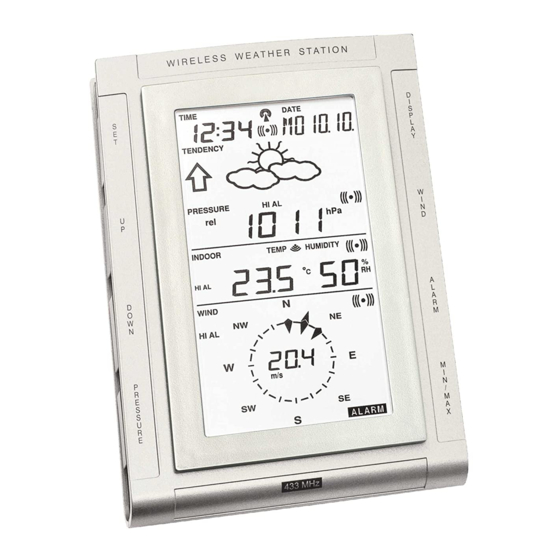
Page 11: Lcd Overview
Without being synchronized, weather data will not be re- ceived. LCD Overview The following illustration shows the full segments of the LCD for description purposes only and will not appear like this during normal operation and use. -
Page 12: Function Test
Low battery indicator 17. Rainfall units (inch or mm) DCF77 radio controlled time 18. Temperature display units icon (ºC or ºF) Date display 19. Outdoor tempera- Time zone display ture/humidity display Date, seconds, alarm time 20 Indoor temperature/humidity and time zone display Alarm icon 21. -
Page 13: Mounting
base station to the sensors otherwise no weather data will be received. Some weather readings such as wind speed and direction may not appear immediately on the LCD if the wind-fan or vane of the wind sensor is moved. This is due to the set reading time intervals for the wind readings. - Page 14 Mounting the Wind Sensor onto a mast Wind-vane Mast Wind-fan Firstly, check that the wind-fan and the wind-vane can rotate freely before fixing the unit. For correct and accurate readings it is important to mount the sensor so that the front (marked E) is pointing in East-West direction.
- Page 15 When securing into place, check that rain excess will not collect and store at the base of the unit but can flow out be- tween the base and the mounting surface (test by pouring clean water). After mounting the rain sensor, connect the cable to the thermo-hygro sensor at the corresponding socket so power supply can be received and data be transmitted to the base station...
-
Page 16: Resetting & Factory Settings
Resetting & factory settings: As previously mentioned, in the event of a power reset to the sensor (for example a change of batteries), the base station has to synchronize to the sensor again otherwise no weather data will be received. To do this, simply press and hold the PLUS(+) key for 2 seconds and a short beep will sound to synchronize the base station to the sensor. - Page 17 alarm Outdoor temperature 0.0ºC (low) 40.0ºC (high) alarm Indoor humidity 35%RH (low) 65%RH (high) alarm Outdoor humidity 45%RH (low) 70%RH (high) alarm Wind chill alarm 10.0ºC (low) 30.0ºC (high) Dew point alarm 0.0ºC (low) 30.0ºC (high) Rainfall 24h alarm 50.0mm Rainfall 1h alarm 1.0mm Wind Speed...
-
Page 18: Function Description
Function Description of the Weather Station After setting up, the following data will be displayed in different sections on the LCD. If this is not the case please observe the notes on “Interferences” below. LCD Section 1: Time, date, seconds, time zone, weather forecasting icons with tendency arrows, air... - Page 19 Sunny Cloudy Rainy Notes to hPa sensitivity setting for weather forecasting: The hPa (Hekto-Pascal) pressure sensitivity can be set to suit the user’s requirement for weather forecasting from 2 hPa to 4 hPa (see Basic Programming below). For areas that experi- ence frequent changes in air pressure (which does not neces- sarily reflect a change in the weather) requires a higher hPa setting compared to an area where the air pressure is stag-...
- Page 20 Weather Data (LCD Section 2) Indoor temperature and humidity are displayed simultaneously in this section. Use the DISPLAY key to toggle through the displays for other weather information: Outdoor temperature/humidity Outdoor wind chill Outdoor dew point Rainfall 24h Rainfall 1h Rainfall total.
-
Page 21: Operation Keys
Operation keys The base station has 8 keys for easy operation. Please refer to the following table for use and function of each key: Further descriptions of the key functions with regard to their immedi- ate range of application can be found in the Programming modes: SET - key - In normal mode to enter the manual... - Page 22 - Wind speed - Wind direction - Wind direction display in degrees ALARM - In normal mode to enter the alarm programming mode - In alarm programming mode to select the following setting modes: - Time alarm setting - Indoor temperature alarm (high & low) - Outdoor temperature alarm (high &...
-
Page 23: Basic Programming Modes
- In basic programming mode acoustic storm alarm ON/OFF - To turn the alarms off 24 hours when the alarm is sounding - In MIN/MAX modes to resets recorded values and recorded dates and times * Press any key to activate the LED Backlight Basic Programming Modes Manual Setting modes The manual setting mode allows the user to change several... -
Page 24: Min/Max Programming Modes
Continue to press the SET key to toggle through the setting mode until the LCD returns to the normal display mode or press the MIN/MAX key at any time to exit. Note! Keeping the PLUS(+) or MINUS(-) key depressed when set- ting certain units in the manual setting mode will in- crease/decrease digits in greater steps. - Page 25 • Outdoor temperature (max or min with time and date) • Outdoor humidity (max or min with time and date) • Outdoor wind chill (max or min with time and date) • Outdoor dew point (max or min with time and date) •...
-
Page 26: Alarm Programming Modes
Alarm Programming Modes Alarm Modes As well as the normal time alarm, this feature will allow users to set a range of specific alarms to meet specific weather and temperature conditions set by the user. The weather station allows for the following 13 alarms modes to be set: Time alarm Indoor temperature high alarm and low alarm Outdoor temperature high alarm and low alarm... - Page 27 Press ALARM key to confirm followed by the MIN/MAX key to return to the normal display mode. Indoor temperature high alarm and low alarm setting 1) Press the ALARM key to enter the normal time alarm 2) Press the ALARM key again to enter indoor temperature high alarm set mode 3) Press and hold the SET key to enter the indoor tempera- ture high setting values (digits will start flashing) and set...
- Page 28 6) Press ALARM key to confirm and press the MIN/MAX key to return the normal display mode or press the ALARM once more to toggle to another alarm setting mode. Indoor humidity high alarm and low alarm setting 1) Press the ALARM key to enter the normal time alarm 2) Continue to press the ALARM key until you reach the indoor humidity high alarm set mode 3) Press and hold the SET key to enter the indoor humidity...
- Page 29 6) Press ALARM key to confirm and press the MIN/MAX key to return the normal display mode or press the ALARM once more to toggle to the to enter another alarm setting mode. Wind chill high alarm and low alarm setting 1) Press the ALARM key to enter the normal time alarm 2) Continue to press the ALARM key until you reach the wind chill high alarm set mode...
- Page 30 Rainfall 24h alarm setting 1) Press the ALARM key to enter the normal time alarm 2) Continue to press the ALARM key until you reach the rain 24 hour alarm set mode 3) Press and hold the SET key to enter the rain setting val- ues (digits will start flashing) and set the desired rain val- ues by using the PLUS(+) or MINUS (-) keys 4) Press ALARM key to confirm and press the MIN/MAX key...
- Page 31 Wind speed high alarm and low alarm setting 1) Press the ALARM key to enter the normal time alarm 2) Continue to press the ALARM key until you reach the wind speed high alarm set mode 3) Press and hold the SET key to enter the wind speed setting values (digits will start flashing) and set the desired wind speed high by using the PLUS(+) or MINUS (-) keys 4) Press ALARM key to confirm and press the MIN/MAX key...
- Page 32 4) Press the MIN/MAX key to confirm and return to the nor- mal display. Storm warning alarm ON/OFF After storm warning alarm setting, the next mode to appear after pressing the SET key is the storm warning ON/OFF. Use the PLUS(+) or MINUS(-) key to change the status to AON or AOFF.
- Page 33 through each alarm mode until it returns to the normal display mode or press the MIN/MAX key at any time to exit the alarm setting modes. When a set weather alarm condition has been activated, that particular alarm will sound and flash for approximately 2 min- utes but will continue to flash until weather conditions have become more steady.
-
Page 34: Auto-Memory For Stored Values
example, if the high temperature alarm is set to +25°C and the current value moves to +25°C, the alarm will be activated (if it has been enabled). Now when the temperature drops to +24.9°C or below and thereafter again increases to beyond +25°C, the data will be blinking, but no alarm will be activated. -
Page 35: Accessories: Extensions Cables
Accessories: adding cable extensions For your convenience, additional telephone cables to increase the connection distance between each of the units may be purchased from any reputable hardware store. Simply add these to the current cables to extend your cable connection distance. - Page 36 Once the sensor is powered up, press and hold the PLUS(+) key for approx. 2 seconds in the normal display mode, the base station will sound a short beep and synchronize to the sensor otherwise no weather data will be received. Battery change only in the base station: Connect power adaptor to base station and power outlet.
- Page 37 High shielding mate- Find a different location for rials between the sensors and/or receiver. See units (thick walls, also Item ‘Transmission steel, concrete, isolat- Range’ below. ing aluminum foil and etc.) Interference from Find a different location for the other sources (e.g. sensors and/or base station.
-
Page 38: Transmission Range
Transmission Range The transmission distance from the thermo-hygro sensor to the base station in open space under optimum conditions is 100 meters. Although the signal transmission may travel though solid surfaces or objects, the following points should be avoided if possible: High frequency interferences of any kind. -
Page 39: Specifications
Specifications Outdoor data Transmission Distance in Open Field: 100 meters max. Temperature Range -29.9°C to +69.9°C (show “OFL” if outside range) Resolution 0.1°C Measuring Range Rel. Humidity 1% to 99% Rain Volume Display 0 to 999.9mm (1h and 24h rainfall) 0 to 2499.9mm (Total rainfall) Resolution... -
Page 40: Liability Disclaimer
altitude of 9,100 me- ters is around 300 hPa) Resolution 0.1 hPa Alarm duration 2 minutes (approx.) Power consumption Base Station Batteries 3 x AA, IEC LR6, 1.5V (Alkaline recommended) or AC power INPUT 230V C 50HZ (use the provided AC/DC adapter only) Thermo-hygro sensor 2 x AA, IEC LR6, 1.5V... - Page 41 • This product must however not be thrown in general rubbish collection points. • As stated on the gift box and labeled on the product, reading the “User manual” is highly recommended for the benefit of the user. • The manufacturer and supplier cannot accept any re- sponsibility for any incorrect readings and any conse- quences that occur should an inaccurate reading take place.
Need help?
Do you have a question about the WS 2307 and is the answer not in the manual?
Questions and answers