Advertisement
Quick Links
Download this manual
See also:
Instruction Manual
SERVICE MANUAL
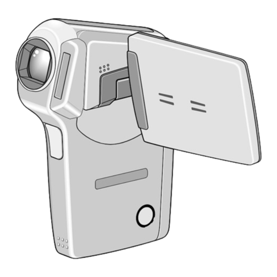
Digital Movie Camera
Contents
1. OUTLINE OF CIRCUIT DESCRIPTION ............................... 3
2. DISASSEMBLY ................................................................... 12
3. ELECTRICAL ADJUSTMENT ............................................. 17
4. USB STORAGE INFORMATION REGISTRATION ............ 22
5. TROUBLESHOOTING GUIDE ............................................ 23
6. PARTS LIST ........................................................................ 24
CIRCUIT DIAGRAMS & PRINTED WIRING BOARDS ........... C1
RoHS
•This product does not contain any hazardous substances prohibited by the RoHS
Directive.
WARNING
•You are requested to use RoHS compliant parts for maintenance or repair.
•You are requested to use lead-free solder.
(This product has been manufactured using lead-free solder. Be sure to follow the
warning given on page 2 when carrying out repair work.)
CAUTION : Danger of explosion if battery is incorrectly replaced.
Replace only with the same or equivalent type recommended by the
manufacturer.
Discard used batteries according to the manufacturer's instructions.
NOTE : 1. Parts order must contain model number, part number, and description.
2. Substitute parts may be supplied as the service parts.
3. N. S. P. : Not available as service parts.
Design and specification are subject to change without notice.
SG112/U, EX, EX2, EX3, GX, PX (R)
FILE NO.
VPC-CG65
(Product Code : 168 081 01)
(U.S.A.) (Canada) (Korea) (Taiwan)
VPC-CG65EX
(Product Code : 168 081 02)
(Europe) (U.K.) (South America)
(China) (Australia) (Hong Kong)
(Russia) (Middle East) (Africa)
(General) (Korea) (Taiwan)
VPC-CG65EXBK
(Product Code : 168 081 05)
(Europe) (U.K.) (South America)
(China) (Australia) (Hong Kong)
(Russia) (Middle East) (Africa)
(General) (Korea) (Taiwan)
VPC-CG65EXG
(Product Code : 168 081 06)
(Europe) (U.K.) (South America)
(China) (Australia) (Hong Kong)
(Russia) (Middle East) (Africa)
(General) (Korea) (Taiwan)
VPC-CG65GX
(Product Code : 168 081 07)
(South America) (China)
(Australia) (Hong Kong)
(General) (Korea) (Taiwan)
VPC-CG65PXBL
(Product Code : 168 081 11)
(General)
REFERENCE No. SM5310699
Advertisement

Related Manuals for Sanyo VPC-CG65


Summary of Contents for Sanyo VPC-CG65
-
Page 1: Table Of Contents
FILE NO. SERVICE MANUAL VPC-CG65 Digital Movie Camera (Product Code : 168 081 01) (U.S.A.) (Canada) (Korea) (Taiwan) VPC-CG65EX (Product Code : 168 081 02) (Europe) (U.K.) (South America) (China) (Australia) (Hong Kong) (Russia) (Middle East) (Africa) (General) (Korea) (Taiwan) - Page 2 PRODUCT SAFETY NOTICE The components designated by a symbol ( ! ) in this schematic diagram designates components whose value are of special significance to product safety. Should any component designated by a symbol need to be replaced, use only the part designated in the Parts List.
-
Page 3: Outline Of Circuit Description
1. OUTLINE OF CIRCUIT DESCRIPTION Pin 1 1-1. CCD CIRCUIT DESCRIPTION 1. IC Configuration The CCD peripheral circuit block basically consists of the fol- lowing ICs. IC931 (MN39830PMJ-A) CCD imager IC901 (AN20112A) V driver IC905 (AD9971BCPZRL) CDS, AGC, A/D converter, H driver vertical TG Pin 13 2. - Page 4 3. IC901 (V Driver) 4. IC905 (H Driver, CDS, AGC and A/D converter) A V driver (IC901) is necessary in order to generate the clocks IC905 contains the functions of H driver, CDS, AGC and A/D (vertical transfer clock and electronic shutter clock) which converter.
- Page 5 1-2. CP1 and VF1 CIRCUIT DESCRIPTION 1. Circuit Description When the TG/SG drives the CCD, picture data passes through 1-1. Digital clamp the A/D and CDS, and is then input to the ASIC as LVDS The optical black section of the CCD extracts averaged val- data.
- Page 6 4. Lens drive block 5. Video clip recording and playback 4-1. Focus drive 5-1. Recording The three control signals (LENS_SD, LENS_CK and The signals from the camera block are input to the ASIC where LENS_EN) which are output from the ASIC (IC101) are con- they are processed, and the image data that is stored in the verted into drive pulses (FOCUS A+, FOCUS A–, FOCUS B+ IC102 SDRAM is input to the IC102 MPEG4 CODEC LSI.
- Page 7 1-3. PWA POWER CIRCUIT DESCRIPTION 1. Outline 3. Motor System Power Output This is the main power circuit, and is comprised of the follow- 5.3 V is output. Feedback for the 5.3 V is provided to the switch- ing blocks. ing controller (Pin (36) of IC501) so that PWM control can be Switching controller (IC501) carried out.
- Page 8 1-4. ST1 STROBE CIRCUIT DESCRIPTION 1. Charging Circuit 2. Light Emission Circuit When UNREG power is supplied to the charge circuit and the When FLCLT signal is input from the ASIC, the stroboscope CHG signal from microprocessor becomes High (3.3 V), the emits light.
- Page 9 1-5. SYA CIRCUIT DESCRIPTION 1. Configuration and Functions For the overall configuration of the SYA block, refer to the block diagram. The SYA block centers around a 8-bit microprocessor (IC301), and controls camera system condition (mode). The 8-bit microprocessor handles the following functions. 1.
- Page 10 SCAN OUT3 Keyscan output 3 SCAN OUT2 Keyscan output 2 SCAN OUT1 Keyscan output 1 SCAN OUT0 Keyscan output 0 H_PHONEJACK Headphone cable detection BAT_I Battery current value detection (analog input) BAT + Battery voltage detection (analog input) Battery temperature detection (analog input) BAT_T BL ON LCD backlight ON/OFF signal (H=ON)
- Page 11 3. Key Operaiton For details of the key operation, refer to the instruction manual. SCAN SCAN RIGHT DOWN LEFT V. REC TELE WIDE PW_TEST TEST PW_ON LCD TURN Table 5-2. Key Operation 4. Power Supply Control The 8-bit microprocessor controls the power supply for the overall system. The following is a description of how the power supply is turned on and off.
-
Page 12: Disassembly
2. DISASSEMBLY 2-1. REMOVAL OF CABI LEFT, LENS ASSEMBLY AND CA1 BOARD 1. Two screws 1.7 x 4 When assembling, 2. Holder strap tighten the screws order. 3. Screw 1.7 x 2.5 a → b → c 4. Open the cover battery. 5. - Page 13 2-2. REMOVAL OF CP1 BOARD 1. Two screws 1.7 x 4 2. Earth batt 3. Button back 4. FPC 5. Two screws 1.7 x 4 6. CP1 board 7. Two connectors 8. Spacer lens right 9. Spacer holder joint 10. Two screws 1.7 x 2.5 11.
- Page 14 2-3. REMOVAL OF ST1 BOARD 10. Remove the solder. 1. Two screws 1.7 x 2 11. Holder speaker 2. Two screws 1.7 x 5 12. Speaker, 8 3. Assy cover joint 4. Two screws 1.4 x 5 13. Remove the solder. 5.
- Page 15 2-4. REMOVAL OF LCD, TB1 BOARD AND VF1 BOARD 1. Screw 1.7 x 2 2. Cover joint 3. Four screws 1.4 x 3 4. Cover LCD back 5. Dec LCD top B 6. Spacer LCD A 7. Two connector 8. Remove the solder. 9.
- Page 16 2-5. BOARD LOCATION VF1 board ST1 board CA1 board CP1 board TB1 board – 16 –...
-
Page 17: Electrical Adjustment
3. Pattern box (color viewer) from the following URL. Turn on the switch and wait for 30 minutes for aging to take http://www.digital-sanyo.com/overseas/service/ place before using Color Pure. It is used after adjusting the chroma meter (VJ8-0192) adjust color temperature to 3100 ±... - Page 18 3-6. The adjustment item which in necessary in part exchange CCD Black Point CCD White Point And White Point USB storage Gyro sensor Factory Lens Language Reset Defect Detect information Defect Detect zero offset Cord Setting Adjustment Setting Adjustment Adjustment In Adjustment adjustment registration...
- Page 19 2. AWB Adjustment Adjustment value determination 150<a1<450, 300<a2<600, 450<a3<750, 600<a4<900, 750<a5<1024 wc0=128 ± 2, wc1=128 ± 2, wc2=130 ± 40 wnc0=128 ± 2, wnc1=128 ± 2, wnc2=130 ± 40 801<ms1<=2500, 1201<ms2<=2900, 1251<ms3<=3100, 1401<ms4<=3600 100<=s1<=220, 100<=s2<=220, 100<=s3<=220, 100<=s4<=220, 100<=s5<=220 ms4>ms3>ms2>ms1 s1>s2>s3>s4>s5 0<=g<=255 0<=o<=255 Adjustment values other than the above are irrelevant.
- Page 20 5. Gyro Sensor Zero Offset Adjustment 3-8. Factory Code Setting Preparation: 1. Check the "Factory Code" display within the Setting group. POWER switch: ON 2. For U.S.A., Canada and NTSC general area If "FC_SANYO_U" does not appear, click on the " "...
- Page 21 3-14. Firmware uploading procedure 3-11. Program data writing to NAND-Memory Carry out program data writing to NAND-memory 1. Uploading the firmware should be carried out if the version after replacing CP1 board. number (COMPL PWB XX-X) on the replacement circuit board is lower than the version of the distributed firmware.
-
Page 22: Usb Storage Information Registration
17.) 2. Double-click on the DscCalDi.exe. 3. Click on the Get button in the USB storage window and check the USB storage data. VID: SANYO PID: CG65 Serial: Rev. : 1.00 4. -
Page 23: Troubleshooting Guide
5. TROUBLESHOOTING GUIDE POWER LOSS INOPERTIVE TAKING INOPERATIVE PUSH SHUTTER PUSH THE POWER BUTTON SW FOR A WHILE HIGH IC301-25, 55 IC301-54 CHECK UNIT SW CHECK POWER SW KEY INPUT SCAN IN 4 INPUT IC501-26, 32, 30, 31 CHECK IC101, IC301, IC301-9, 38, 62 (P ON, PAON, PWA BLOCK,... -
Page 24: Parts List
BATTERY CHARGER 645 089 8990 BATTERY,RECHARGE,LI-ION 636 102 2545 DISC,CD-ROM SSP G112 U1 (N.S.P.) (Sanyo software pack Disk 1) (PDF instruction manual: English, French, Spanish, German, Dutch, Italian, Simplified Chinese, Traditional Chinese, Korean, Russian) 636 102 2552 DISC,CD-ROM SSP G112 U2 (N.S.P.) - Page 25 Table of accessories Table 6-1. Accessories...
- Page 26 CABINET AND CHASSIS PARTS 1 LOCATION PARTS NO. DESCRIPTION LOCATION PARTS NO. DESCRIPTION 636 102 2941 COMPL,CABI LEFT-SG112/J, 636 102 7038 DEC LCD-SG112/J3, VPC-CG65EXG ONLY EXCEPT VPC-CG65EXG 636 099 5352 DEC RIGHT-SG111/J2 636 102 2958 COMPL,CABI LEFT-SG112/J3, 636 099 1583 SPACER LENS RIGHT-SG111/J VPC-CG65EXG ONLY 636 100 2134...
- Page 27 CABINET AND CHASSIS PARTS 1 Cabinet 1 SG112/J PARTS LIST 1...
-
Page 28: Cabinet And Chassis Parts 2
VPC-CG65PXBL ONLY 312 070 1208 SPSCR E2PN1.4X3WP, VPC-CG65EXBK, 636 101 4588 SPACER LCD A-SG111/J VPC-CG65EXG 636 102 3108 ASSY COV LCD BACK-SG112/J, VPC-CG65, 312 060 9504 SPECIAL SCREW-1.7X2.5 VPC-CG65EX, VPC-CG65GX 411 181 2705 SCR PAN PCS-1.4X2 636 102 3115 ASSY COV LCD BACK-SG112J2, 411 194 8404 SCR PAN PCS 1.7X2.0... - Page 29 CABINET AND CHASSIS PARTS 2 Cabinet 2 SG112/J PARTS LIST 2...
-
Page 30: Electrical Parts
ELECTRICAL PARTS Note: 1. Materials of Capacitors and Resistors are abbreviated as follows ; Resistors Capacitors MT-FILM Metallized Film Resistor MT-POLYEST Metallized Polyester Capacitor MT-GLAZE Metallized Glaze Resistor MT-COMPO Metallized Composite Capacitor OXIDE-MT Oxide Metallized Film Resistor TA-SOLID Tantalum Solid Capacitor AL-SOLID Aluminum Solid Capacitor NP-ELECT... - Page 31 LOCATION PARTS NO. DESCRIPTION LOCATION PARTS NO. DESCRIPTION C1035 303 433 1102 CERAMIC 1U K 10V C9001 303 409 3406 CERAMIC 0.1U K 16V C1036 303 419 4004 CERAMIC 0.1U K 10V C9002 303 419 4004 CERAMIC 0.1U K 10V C1038 303 375 0300 CERAMIC...
- Page 32 LOCATION PARTS NO. DESCRIPTION LOCATION PARTS NO. DESCRIPTION R1042 301 302 1307 MT-GLAZE 100 JA 1/20W R9002 301 226 1506 MT-GLAZE 0.000 ZA 1/16W R1063 301 224 8804 MT-GLAZE 100 JA 1/16W R9015 301 226 1506 MT-GLAZE 0.000 ZA 1/16W R1064 301 225 1903 MT-GLAZE...
- Page 33 LOCATION PARTS NO. DESCRIPTION LOCATION PARTS NO. DESCRIPTION R7003 301 309 2604 MT-GLAZE 470K DC 1/16W (N.S.P.) (RECHARGEABLE BATTERY) R7005 301 309 2604 MT-GLAZE 470K DC 1/16W (N.S.P.) Z6001 945 051 6000 BATTERY,RECHARGE R9008 301 225 0906 MT-GLAZE 82K JA 1/16W (N.S.P.) (CONNECTORS) R9014 301 226 1506...
- Page 34 SANYO Electric Co., Ltd. Osaka, Japan Printed in Japan Mar./’07...
Need help?
Do you have a question about the VPC-CG65 and is the answer not in the manual?
Questions and answers