Advertisement
Quick Links
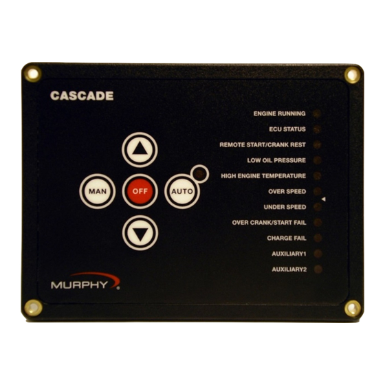
Cascade CD101 Auto-Start Controller
Installation and Operations Manual Version: 2.00
Please read the following information before installing. A visual inspection of this product for damage during shipping
is recommended before mounting. It is your responsibility to have a qualified person install this unit and make sure it con-
forms to NEC and local codes.
WARNING
BEFORE BEGINNING INSTALLATION OF THIS MURPHY PRODUCT
✔ ✔ Disconnect all electrical power to the machine.
✔ ✔ Make sure the machine cannot operate during installation.
✔ ✔ Follow all safety warnings of the machine manufacturer.
✔ ✔ Read and follow all installation instructions.
Description
The Cascade controller offers automatic start/stop control with easy configuration for
a broad number of engine driven applications.
Specifications
Power input: 9-35VDC continuous - operates during total blackout for 2 sec. min.
Power consumption: Sleep Mode (Manual): 1mA typical;(Automatic) 4mA typical.
Running Mode (Manual): 20mA typical; (Automatic): 24mA typical.
Operating/Storage temperature: -40 to 85°C; (-40 to 185°F).
Humidity: 0-100%, non-condensing.
Housing: UV stabilized black polycarbonate and epoxy encapsulation. Weather tight
and includes sealing gasket to keep moisture and debris out of enclosure. Properly
mounted controller will maintain NEMA4 / IP65 rating of enclosure.
Vibration: Rated to 6G.
Impact: Rated to 10G.
Inputs: Dedicated digital inputs for low oil pressure, high engine temperature,
remote start, DC charge fail/Alternator fail. Two aux inputs are configurable for mul-
tiple functions.
Outputs: 7 – 4 auxiliary, configurable (1A DC protected). 3 dedicated outputs for
Crank, Fuel/ECU, Alternator excitation.
Crank attempts: 3, 5, 10, Continuous.
Crank Rest: 5-60 seconds, adjustable.
Shutdown lockout time delay: 5, 10, 15, 20, 25, 30 seconds.
Crank disconnect speed setting: Field settable 0-9999 RPM (16-60Hz AC freq input).
Overspeed/underspeed trip point setting: ±5 to 50% of nominal.
Speed sensing inputs: Magnetic pickup (5-120VAC RMS / 0-10 kHz) & AC fre-
quency (30-600VAC RMS / 16-80 Hz).
CANbus interface: Directly reads engine speed, & engine status data* from SAE-
J1939 enabled engines.
MODbus interface: In J1939 applications drives PVA series analog gages
*Engine status data limited to low oil pressure, high engine temperature, "Wait to
start" status, Warning & Fault lamp information, and communication error.
To Install, You Will Need:
#2 Phillips (cross head) head screwdriver
Nut driver to fit #6-32x1/2" machine nuts
Wire for hook-up (rising cage clamp suitable for 14-24 gage wire).
MURPHY, the Murphy logo, Cascade, and SWICHGAGE(r) are registered and/or common law trademarks of
Murphy Industries, Inc.
This document, including textual matter and illustrations, is copyright protected by Murphy Industries, Inc.,
with all rights reserved. (c) 2004 Murphy Industries, Inc.
C
US
R
LISTED
LISTED
E236550
GENERAL INFORMATION
Mounting the Cascade
Cut a 5.63 x 4.06 in. (143 x 103mm) mounting hole, and drill four 0.169 in.(4.3 mm)
diameter holes for the mounting screws. See Schematic below:
Recommended Wiring Practices
1. To help prevent electrical noise and voltage drop to the controller during cranking
and preheat, wire the controller DC power connections directly to the cranking
battery. This will also help improve "Low battery" starting capability.
2. When using a battery charger, it should be connected directly to the battery to
help prevent electrical noise which could cause an engine ECU or associated
equipment to operate erratically.
3. Never route low voltage DC wiring in the same conduit as high voltage AC
wiring. Noise from electrical loads such as motors and variable frequency drives
can be coupled into the engine ECU, governor, or associated equipment and may
cause erratic operation.
4. Always use twisted shielded pair wires for the magnetic pickup wiring. Ground one
end of the shield only.
5. In spark ignited engine applications, always use resistive spark plugs and spark
plug wires, as these greatly reduce the amount of radiated noise.
6. Always place a snubbing diode (sometimes also called an anti-flyback, anti-kick-
back or reverse bias diode) directly across any inductive load. This helps elimi-
nate a common source of electrical noise, as well as increases the operating life-
time of any solid state output.
7. Always use twisted shielded pair communications wiring for RS-485, and SAE
standard wire for J1939. Make sure that terminating resistors (if required) have
the correct rating and are installed properly.
Installation 00-02-0594 page 1 of 12
Cut Out Dimensions
5.63 x 4.06 in. (143 x 103 mm).
Gasket
0.169 in. (4.3 mm)
1 2 3 4
diameter 4 places
OPEN
24
25
26
27
6.06 in. (154 mm)
6.57 in. (167 mm)
Warning:
The CASCADE is designed for pilot-duty use and its outputs are for
control only. Wire the CASCADE controller with 18 gage stranded wire.
Important:
For applications involving automatic start equipment, we strongly
recommend the installation of an appropriate Emergency Stop device.
00-02-0594
Effective 10-07
Section 40 & 75
Not used 15
Aux. 4 out 14
Aux. 3 out 13
Remote call to run 12
Aux. 2 in 11
Aux. 1 in 10
Hi engine temp. 9
Lo oil press. 8
Alt. Excite. 7
Aux. 2 out 6
Aux. 1 out 5
Crank 4
Fuel/ECU 3
-V Batt. 2
+V Batt. 1
5.63 in. (143 mm)
Advertisement

Related Manuals for Murphy Cascade CD101


Summary of Contents for Murphy Cascade CD101
- Page 1 Wire for hook-up (rising cage clamp suitable for 14-24 gage wire). nate a common source of electrical noise, as well as increases the operating life- MURPHY, the Murphy logo, Cascade, and SWICHGAGE(r) are registered and/or common law trademarks of time of any solid state output.
- Page 2 LED Status Lights Setting Up the Cascade Move Switch toward ● To enter the SETUP MODE first remove DC Eleven LEDs separated into two banks (see “Fig. 1”) are provided on the faceplate. the numbers to Turn On power to the Cascade controller for approximately The LEDs Bank 1 includes 6 LEDs and Bank 2 includes 5.
- Page 3 Table 1. Parameter Values and Corresponding LED Indication LEDs shown here form a binary code indicating the configuration value. Shown from Top to bottom the LEDs read from Left to Right (see Fig.1). A filled dot means LED is ON. Parameter Parameter # Description...
- Page 4 Table 1. Parameter Values and Corresponding LED Indication (continued) LEDs shown here form a binary code indicating the configuration value. Shown from Top to bottom the LEDs read from Left to Right (see Fig.1). A filled dot means LED is ON. Parameter Parameter # Description...
- Page 5 Table 1. Parameter Values and Corresponding LED Indication (continued) LEDs shown here form a binary code indicating the configuration value. Shown from Top to bottom the LEDs read from Left to Right (see Fig.1). A filled dot means LED is ON. Parameter Parameter # Description...
- Page 6 Parameter Parameter # Description LED Bank 1 Value (*= default) LED Bank 2 # Description LED Bank 1 Value (*= default) LED Bank 2 ●●❍●❍● ❍❍❍❍❍ ●●❍❍●❍ ❍❍❍❍❍ Run Speed Flywheel Tooth ❍❍❍❍● ❍❍❍❍● (ECU or MPU Count (MPU speed ❍❍❍●❍...
- Page 7 Table 4. Configuration Error Codes The eight LEDs shown in the table below form an 8-bit binary error code to indicate the type of configuration error detected The following error codes are currently defined: Error Code(s) LED Indication Error 1 – 63 (varies) Individual configuration parameter number is out of range.
- Page 8 Typical Wiring Diagrams (continued) Installation 00-02-0594 page 8 of 12...
- Page 9 Typical Wiring Diagrams (continued) Installation 00-02-0594 page 9 of 12...
- Page 10 Typical Wiring Diagrams (continued) Installation 00-02-0594 page 10 of 12...
- Page 11 Typical Wiring Diagrams (continued) Installation 00-02-0594 page 11 of 12...
- Page 12 CALL MURCAL TO PLACE YOUR ORDER MurCal P:(661)272-4700 F:(661)947-7570 In order to consistently bring you the highest quality, full featured products, www.murcal.com e-mail: sales@murcal.com we reserve the right to change our specifications and designs at any time. Installation 00-02-0594 page 12 of 12...
Need help?
Do you have a question about the Cascade CD101 and is the answer not in the manual?
Questions and answers