
Related Manuals for Lectrosonics T1 IFB


Summary of Contents for Lectrosonics T1 IFB
- Page 1 INSTRUCTION MANUAL Multi-Frequency IFB Transmitter Fill in for your records: Serial Number: Purchase Date: Rio Rancho, NM, USA www.lectrosonics.com...
- Page 2 LECTROSONICS, INC.
-
Page 3: Table Of Contents
General Technical Description ................................5 Audio Input Interface .................................... 5 Audio Processor ....................................5 Compandor Noise Reduction ................................5 T1 IFB Transmitter Block Diagram ................................ 5 Pilot Tone ......................................6 Frequency Synthesizer ..................................6 Power Delay ......................................6 Microcontroller ...................................... 6 Transmitter ...................................... -
Page 4: Introduction
50 Ohm BNC connector on the transmitter. companion R1 or R1a IFB Receivers allow on-air talent to monitor program audio and receive cues from Only the T1 IFB Transmitter is covered in this manual. directors and other production personnel. Companion receivers are covered in separate manuals. -
Page 5: General Technical Description
Multi-Frequency IFB Transmitter General Technical Description The T1 IFB Transmitter is comprised of a number of Warning: Direct connection to a phone line can functional subsystems, including Audio Input Interface, damage the transmitter’s inputs. Audio Processor, Pilot Tone, Frequency Synthesizer,... -
Page 6: Pilot Tone
Synthesizer time to fully stabilize. When the transmitter is powered OFF, the Pilot Tone is first turned off muting the audio at the receiver before the rest of the transmitter is powered down. This prevents clicks, thumps or feedback from entering the sound system. LECTROSONICS, INC. -
Page 7: Front Panel Controls And Functions
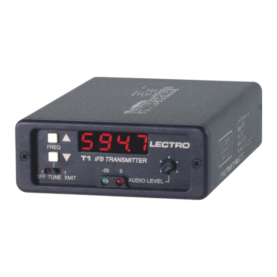
Multi-Frequency IFB Transmitter Front Panel Controls and Functions Freq Buttons (Up and Down) T1 Front Panel The transmitter frequency is changed by pressing the appropriate button (see Note). Each push will change the frequency, up or down, in 100 kHz increments, or one channel at a time. -
Page 8: Rear Panel Controls And Functions
-40 dBu 3 = Lo 1 = Common LINE 2 = Hi +4 dBu 3 = Lo 1 = Common RTS1 2 = Hi +4 dBu 1 = Common RTS2 3 = Hi +4 dBu 1 = Common LECTROSONICS, INC. -
Page 9: Installation And Operation
Multi-Frequency IFB Transmitter Installation and Operation 5) Attach the antenna (or antenna cable) to the BNC 1) The T1 transmitter is shipped with pin 1 of the XLR connector on the rear panel. input connector tied directly to ground. If a floating input is desired, a Ground Lift Jumper is provided. -
Page 10: Operating Notes
ARG15/ARG100 ARG15/ARG100 Coaxial cables for remote antennas available from Lectrosonics in a variety of lengths from 2 to 100 ft. RMP195 4 channel rack mount for up to four T1 IFB receivers. Rocker switch installed to work as a master power switch if desired. -
Page 11: Troubleshooting
Multi-Frequency IFB Transmitter Troubleshooting Symptom: Possible Cause: Display Dead or Blinking On and Off 1) External power supply disconnected or inadequate. 2) The External DC power input is protected by an auto-reset polyfuse. Disconnect power and wait about 10 seconds for the fuse to reset. -
Page 12: Frequency Blocks And Ranges
(a “block”) as shown below. The transmitter will tune to any of 256 different frequencies The T1 IFB transmitter antennas are color coded to within this factory assigned block. indicate the frequency block that they operate within. -
Page 13: Specifications
Specifications subject to change without notice. Emission designator: 80KOF3E The T1 IFB transmitter is FCC type accepted under Part 74: 470 - 608MHz and 614 - 806MHz The FCC requires that the following statement be included in this manual: This device complies with FCC radiation exposure limits as set forth for an uncontrolled environment. This device should be installed and operated so that its antenna(s) are not co-located or operating in conjunction with any other antenna or transmitter. -
Page 14: Service And Repair
There are no adjustments inside that will make a malfunctioning unit start working. LECTROSONICS’ Service Department is equipped and staffed to quickly repair your equipment. In warranty repairs are made at no charge in accordance with the terms of the warranty. Out-of-warranty repairs are charged at a modest flat rate plus parts and shipping. - Page 15 Multi-Frequency IFB Transmitter Rio Rancho, NM...
-
Page 16: Limited One Year Warranty
This warranty does not apply to used or demonstrator equipment. Should any defect develop, Lectrosonics, Inc. will, at our option, repair or replace any defective parts without charge for either parts or labor. If Lectrosonics, Inc. cannot correct the defect in your equipment, it will be replaced at no charge with a similar new item.
Need help?
Do you have a question about the T1 IFB and is the answer not in the manual?
Questions and answers