
Related Manuals for Lectrosonics T4


Summary of Contents for Lectrosonics T4
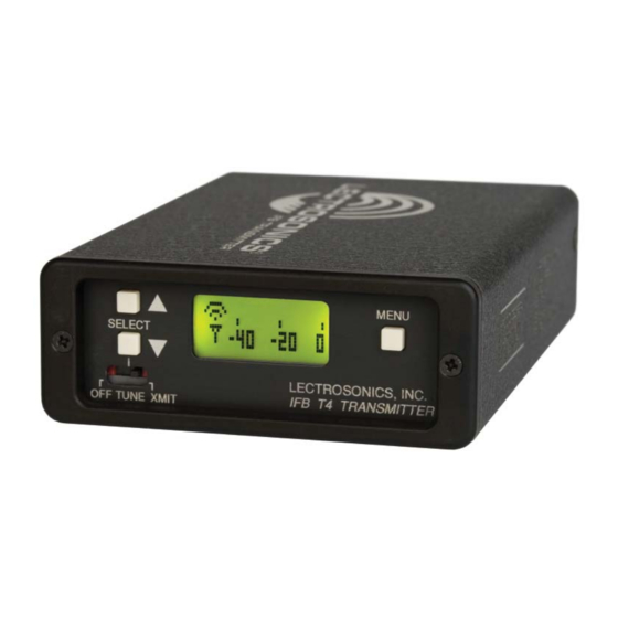
- Page 1 INSTRUCTION MANUAL Multi-Frequency IFB Transmitter ™ Featuring Digital Hybrid Wireless Technology Fill in for your records: Serial Number: Rio Rancho, NM, USA Purchase Date: www.lectrosonics.com...
- Page 2 LECTROSONICS, INC.
-
Page 3: Table Of Contents
T4 IFB (Interruptible Foldback) trans- bronze cable that connects to a 50 Ohm BNC connector mitter. The T4 is the result of over 100 years of engi- on the transmitter. neering experience with the very latest components, in a design that addresses the most demanding profes- Only the T4 IFB Transmitter is covered in this manual. -
Page 4: General Technical Description
944MHz band. complementary system in the receiver recovers (de- The T4 uses 20 kHz deviation in the IFB and 100 series compresses) the original dynamics of the signal for full modes for an effi cient use of bandwidth. The 200 audio quality. -
Page 5: Pilot Tone
Frequency Synthesizer Antenna System The antenna on the T4 consists of a fl exible 1/4 wave- The transmitter uses a synthesized, frequency select- length bronze cable, detachable via a BNC connector. able main oscillator. The frequency is extremely stable The 50 ohm output connector works conveniently with a over a wide temperature range and over time. -
Page 6: Front Panel Controls And Functions
MENU button while momentarily pressing the UP or Power Up Sequence DOWN button. The T4 will “remember” the last channel selected when the unit is turned off, and it will set itself When the OFF/TUNE/XMIT switch is fi rst turned on, to that frequency when the unit is reenergized. - Page 7 Multi-Frequency IFB Transmitter T4 Menu Diagram Rio Rancho, NM...
-
Page 8: Rear Panel Controls And Functions
Rear Panel Controls and Functions T4 Rear Panel 12 VDC (Power Input Connector) The T4 is designed to be used with the CH20 external (or equivalent) power source, which is plugged into the 6-18 VDC external power input connector. The nominal voltage to operate the unit is 12 VDC;... -
Page 9: Installation And Operation
Multi-Frequency IFB Transmitter Installation and Operation 1) The T4 transmitter is shipped with pin 1 of the XLR 5) Attach the antenna (or antenna cable) to the BNC input connector tied directly to ground. If a fl oating connector on the rear panel. -
Page 10: Operating Notes
This gain full modulation, regardless of the gain control setting. adjustment is used to match the T4 input level to the The limiter uses a true absolute value circuit to detect incoming signal from the sound source to provide full both positive and negative peaks. -
Page 11: Troubleshooting
Multi-Frequency IFB Transmitter Troubleshooting Symptom: Possible Cause: Display Dead 1) External power supply disconnected or inadequate. 2) The External DC power input is protected by an auto-reset polyfuse. Disconnect power and wait about 10 seconds for the fuse to reset. No Transmitter Modulation 1) AUDIO LEVEL turned all the way down. -
Page 12: Frequency Blocks And Ranges
In this case, 685.500 MHz falls within block 26. Block 944 is an exception to this block numbering sys- Each T4 transmitter is built to cover a pre-selected tem and depicts the actual frequency of the block since range of frequencies (a “block”) as shown below. The it is only a 6MHz band with 78 frequency channels. -
Page 13: Specifi Cations
Specifi cations subject to change without notice. Emission designator: 180KF3E The T4 IFB transmitter is FCC type accepted under Part 74: 470 - 608MHz, 614 - 806MHz and 944.1 – 951.9MHz. The FCC requires that the following statement be included in this manual: This device complies with FCC radiation exposure limits as set forth for an uncontrolled environment. -
Page 14: Service And Repair
There are no adjustments inside that will make a malfunctioning unit start working. LECTROSONICS’ Service Department is equipped and staffed to quickly repair your equipment. In warranty repairs are made at no charge in accordance with the terms of the warranty. Out-of-warranty repairs are charged at a modest fl... - Page 15 Multi-Frequency IFB Transmitter Rio Rancho, NM...
-
Page 16: Limited One Year Warranty
This warranty does not apply to used or demonstrator equipment. Should any defect develop, Lectrosonics, Inc. will, at our option, repair or replace any defective parts without charge for either parts or labor. If Lectrosonics, Inc. cannot correct the defect in your equipment, it will be replaced at no charge with a similar new item.
Need help?
Do you have a question about the T4 and is the answer not in the manual?
Questions and answers