Table of Contents
Advertisement
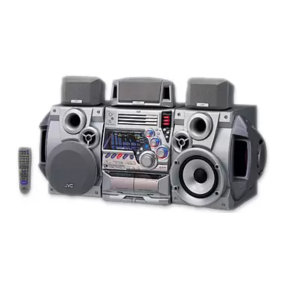
SERVICE MANUAL
COMPACT COMPONENT SYSTEM
MX-DVA9/MX-DVA9R
SP-MXG79
(SP-DSC99TN)
Center unit
CA-MXDVA9/CA-MXDVA9R
Contents
Safety Precautions
CA-MXDVA9/CA-MXDVA9R
(SP-DSS99TN)
Speaker unit
SP-MXDVA9/SP-MXDVA9R
SP-MXG79(Front speaker)
SP-DSC99TN(Center speaker)
SP-DSS99TN(Surround speaker)
1-2
1-4
1-5
1-6
1-7
COPYRIGHT
2001 VICTOR COMPANY OF JAPAN, LTD.
MX-DVA9R
B -------------------------- U.K.
EN ------- Northern Europe
SP-MXG79
MX-DVA9
A ------------------------- Australia
US ---------------------- Singapore
UW ---------- Brazil,Mexico,Peru
UJ --------------------- U.S.Military
UG - Turkey,South Africa,Egypt
UN ----------------------------Asean
MX-DVA9/MX-DVA9R
Area suffix
Area suffix
1-28
1-34
1-35
1-35
1-36
No.21040
Oct. 2001
Advertisement
Table of Contents

Related Manuals for JVC MX-DVA9


Summary of Contents for JVC MX-DVA9
-
Page 1: Table Of Contents
MX-DVA9/MX-DVA9R SERVICE MANUAL COMPACT COMPONENT SYSTEM MX-DVA9/MX-DVA9R Area suffix MX-DVA9R B -------------------------- U.K. EN ------- Northern Europe SP-MXG79 CA-MXDVA9/CA-MXDVA9R SP-MXG79 Area suffix MX-DVA9 A ------------------------- Australia US ---------------------- Singapore UW ---------- Brazil,Mexico,Peru (SP-DSC99TN) (SP-DSS99TN) UJ --------------------- U.S.Military UG - Turkey,South Africa,Egypt... - Page 2 MX-DVA9/MX-DVA9R 1. This design of this product contains special hardware and many circuits and components specially for safety purposes. For continued protection, no changes should be made to the original design unless authorized in writing by the manufacturer. Replacement parts must be identical to those used in the original circuits. Services should be performed by qualified personnel only.
- Page 3 MX-DVA9/MX-DVA9R (U.K only) 1. This design of this product contains special hardware and many circuits and components specially for safety purposes. For continued protection, no changes should be made to the original design unless authorized in writing by the manufacturer.
-
Page 4: Preventing Static Electricity
MX-DVA9/MX-DVA9R Preventing static electricity Electrostatic discharge (ESD), which occurs when static electricity stored in the body, fabric, etc. is discharged, can destroy the laser diode in the traverse unit (optical pickup). Take care to prevent this when performing repairs. 1.1. Grounding to prevent damage by static electricity Static electricity in the work area can destroy the optical pickup (laser diode) in devices such as DVD players. -
Page 5: Precautions For Service
MX-DVA9/MX-DVA9R Precautions for service Handling of Traverse Unit and Laser Pickup 1. Do not touch any peripheral element of the pickup or the actuator. 2. The traverse unit and the pickup are precision devices and therefore must not be subjected to strong shock. -
Page 6: Important For Laser Products
MX-DVA9/MX-DVA9R Important for laser products 5.CAUTION : If safety switches malfunction, the laser is able 1.CLASS 2 LASER PRODUCT to function. 2.DANGER : Invisible laser radiation when open and inter 6.CAUTION : Use of controls, adjustments or performance of lock failed or defeated. Avoid direct exposure to beam. -
Page 7: Disassembly Method
MX-DVA9/MX-DVA9R Disassembly method Metal cover <Main body> Removing the metal cover (See Fig.1 to 3) Remove the six screws A on the back of the body. Remove the two screws B on both sides of the body. Remove the metal cover from the body by lifting the rear part of the cover. - Page 8 MX-DVA9/MX-DVA9R Front panel assembly Removing the DVD mechanism assembly (See Fig.4 to 7) Prior to performing the following procedure, remove the metal cover. Disconnect the card wire from connector CN542 on the main board on the right side of the body.
- Page 9 MX-DVA9/MX-DVA9R Power amplifier board (2) Removing the front panel assembly Main board CN703 Wire clamp CN500 (See Fig.8 to 12) Prior to performing the following procedure, remove CN505 the metal cover and DVD changer mechanism assembly. CN510 Disconnect the card wires from connector CN500, CN505 and CN510 on the main board respectively.
- Page 10 MX-DVA9/MX-DVA9R Removing the tuner board Tuner board Rear panel (See Fig.13 and 14) Prior to performing the following procedure, remove Plastic rivet the metal cover. Disconnect the card wire from connector CN1 on the tuner board on the right side of the body.
- Page 11 MX-DVA9/MX-DVA9R Removing the main board CN500 Front panel assembly (See Fig.18 and 19) CN505 Main board Prior to performing the following procedure, remove CN510 CN513 the metal cover, the DVD changer mechanism assembly, the rear panel and the antenna board.
- Page 12 MX-DVA9/MX-DVA9R Removing the power board / power cord CN218 (See Fig.21) CN219 Prior to performing the following procedure, remove Power board the metal cover, the DVD changer mechanism CN250 assembly and the rear panel. Power cord Disconnect the wire from connector CN218 and CN219(only US/UJ/UG/UN/UW) on the power board.
- Page 13 MX-DVA9/MX-DVA9R Removing the power amplifier board (1) Main board CN703 CN513 Wire clamp / power amplifier board (2) / heat sink (See Fig.25 to 27) Power amplifier Prior to performing the following procedure, remove board (2) the metal cover, the DVD changer mechanism assembly, the rear panel, the antenna board and the analog output board.
- Page 14 MX-DVA9/MX-DVA9R Transformer board Removing the power transformer assembly CN220 Wire clamps (See Fig.28 and 29) Prior to performing the following procedure, remove the metal cover, the DVD changer mechanism CN219 assembly and the rear panel. Disconnect the wire from connector CN218 and CN219(only US/UJ/UG/UN/UW) on the power board.
-
Page 15: Front Panel Assembly
MX-DVA9/MX-DVA9R <Front panel assembly> Head amplifier & mechanism control board CN306 Prior to performing the following procedure, remove the metal cover, the DVD changer mechanism assembly and the front panel assembly. Removing cassette mechanism assembly (See Fig.31) Disconnect the card wire from connector CN306 on the head amplifier &... - Page 16 MX-DVA9/MX-DVA9R Removing the CD eject board DVD eject board (See Fig.35) FW915 (Solding) Remove the three screws Q attaching the DVD eject board. If necessary, unsolder FW915 on the DVD eject board. Fig.35 Removing the preset / tuning switch Preset / tuning switch board board (See Fig.36 and 37)
- Page 17 MX-DVA9/MX-DVA9R <Speaker unit section> Removing the side cover (See Fig.1) Remove the six screws A on the side of the body. Removing the squawker speaker (See Fig.2) Side cover Prior to performing the following procedure, remove the side cover. Remove the four screws B on the side of the body.
- Page 18 MX-DVA9/MX-DVA9R Tweeter speaker Fig.5 Removing the woofer speaker (See Fig.6) Prior to performing the following procedure, remove the side cover and the front cover. Remove the four screws E on the front of the body. Pull out the woofer speaker toward the front and disconnect the wire (yellow and black,blue and black) from the two speaker terminals.
- Page 19 MX-DVA9/MX-DVA9R DVD Changer Mechanism Section Removing the DVD Servo control board Remove the Metal cover. Remove the DVD changer mechanism assembly. From bottom side the DVD changer mechanism assembly, remove the one screw 1 retaining the DVD Servo control board.
- Page 20 MX-DVA9/MX-DVA9R Stopper Check whether the lifter unit stopper has been caught into the hole at the section "E" of DVD tray assembly as shown in Fig.5. Make sure that the driver unit elevator is positioned as shown in Fig.6 from to the second or fifth hole on the left side face of the DVD Traverse mechanism assembly.
- Page 21 MX-DVA9/MX-DVA9R Cams R1, R2 assembly Removing the DVD mechanism assembly(See Fig.10) While turning the cams R1 and R2 assembly in the arrow direction "H" . align the shaft "I" of the DVD mechanism assembly to the position shown in Fig.10.
-
Page 22: See Fig
MX-DVA9/MX-DVA9R Removing the actuator motor boad (See Fig.14, 15) Motor L Motor R Absord the four soldered positions "M" of the right and left motors with a soldering absorber(See Fig.14). Remove the two screws 7 retaining the actuator motor board(See Fig.14). - Page 23 MX-DVA9/MX-DVA9R Removing the actuator motor and belt Gear bracket (See Fig.19~22) Remove the two screws 10 retaining the gear bracket (See Fig.19). While pressing the pawl "P" fixing the gear bracket in the arrow direction, remove the gear bracket Pulley gear (See Fig.19).
- Page 24 MX-DVA9/MX-DVA9R Slit washer Removing the cams R1/R2 assembly and cam gear L(See Fig.23) Cam R2 Slit washer Remove the slit washer fixing the cams R1 and R2 assembly. Cam gear L By removing the two pawls "S" fixing the cam R1, separate R2 from R1.
-
Page 25: Cassette Mechanism Section
MX-DVA9/MX-DVA9R < Cassette Mechanism Section > Cassette mechanism Removing the Playback,Recording and Eraser Heads (See Fig.1~3) 1. While shifting the trigger arms seen on the right side of the head mount in the arrow direction,turn Flywheel R the flywheel R in counterclockwise direction until the head mount has gone out with a click (See Fig. - Page 26 MX-DVA9/MX-DVA9R Removing the head Amp.and Mechanism Control P.C.Board (See Fig. 4) 1.Remove the cassette mechanism assembly. Head amplifier & 2.After turning over the cassette mechanism mechanism control board assembly,remove the five screws "A" retaining the head amp. and mechanism control P.C.
- Page 27 MX-DVA9/MX-DVA9R Removing the Capstan Motor (See Fig. 8) Capstan motor From the joint bracket, remove the two screws "C" retaining the capstan motor. Joint bracket Removing the Flywheel (See Fig. 9,10) 1.Remove the head amp. and mechanism control P.C.Board. 2.Remove the capstan motor assembly.
-
Page 28: Adjustment Method
MX-DVA9/MX-DVA9R Adjustment method Measurement instruments required for adjustment Radio input signal 1. Low frequency oscillator, AM modulation frequency : 400Hz This oscillator should have a capacity to output 0dBs Modulation factor : 30% to 600ohm at an oscillation frequency of 50Hz-20kHz. -
Page 29: Dvd Section
MX-DVA9/MX-DVA9R DVD section TEST MODE FOR DVD a INITIALISE THE DVD UNIT BOARD Insert A/C Power Cord b) At standby mode press Stop Button and CANCEL/DEMO button. Wait 4 seconds & for the display of " TEST VERSION REGION " i.e. TEST JC 1 c) Press the 'ENTER' button on remocon. - Page 30 MX-DVA9/MX-DVA9R Integrated wiring for adjustment Extension cord 1. Place a board on top of the unit and put the QUQ605-4040AJ changer on it. Then carry out the wiring of the main unit. 2. Connect a extension cable to the traverse mechanism for adjustment and then connect them to the changer.
- Page 31 MX-DVA9/MX-DVA9R Arrangement of adjusting positions Cassette mechanism section (Mechanism A section) Cassette mechanism section (Back side) Head azimuth Head azimuth adjusting screw adjusting screw (Reverse side) (Forward side) Head azimuth Head azimuth Playback, recording and eraser adjusting screw adjusting screw...
- Page 32 MX-DVA9/MX-DVA9R Tape recorder section Adjusting Items Measurement Standard Measurement method positions conditions values Confirmation Adjust the head Test tape Maximum 1.Playback the test tape VT703L(10kHz). of head angle azimuth screw :VT703L(10kHz) output 2.With the playback mechanism or recording & only when the...
- Page 33 MX-DVA9/MX-DVA9R Electrical performance Adjusting Items Measurement Standard Measurement method positions conditions values Adjustment of AC-225 *Mode : Forward or 1.With the recording and playback mechanism, recording bias :4.20 A reverse mode load the test tapes(AC-225 to TYP ),and set the...
-
Page 34: Flow Of Functional Operation Until Toc Read
MX-DVA9/MX-DVA9R Flow of functional operation until TOC read Check Point Slider turns REST Play Key Power ON Confirm that the voltage at the pin5 SW ON. of CN801 is "H"\"L"\"H". Automatic tuning of TE offset Check that the voltage at the... -
Page 35: Maintenance Of Laser Pickup
MX-DVA9/MX-DVA9R Maintenance of laser pickup Replacement of laser pickup (1) Cleaning the pick up lens Before you replace the pick up, please try to Turn off the power switch and, disconnect the clean the lens with a alcohol soaked cotton power cord from the ac outlet. -
Page 36: Description Of Major Ics
MX-DVA9/MX-DVA9R Description of major ICs MN102L62GEJ (IC401) : Unit CPU 1.Terminal layout 2.Pin function Function Symbol Symbol Function Pin No. Pin No. Micon wait signal input FGIN WAIT Read enable Spindle muting output to IC251 Serial enable signal for ADSC... - Page 37 MX-DVA9/MX-DVA9R AN8702FH(IC101):Frontend processor 1.Pin layout RFINN PC01 RFINP TESTSG PC02 AGCO TGBAL AGCG TBAL PEAK FBAL BOTTOM AN8702FH POFLT RFENV DTRD IDGT OFTR STANDBY DCRF VCC3 STDI RFOUT RSEL RFDIFO JLINE GND3 2.Pin function Symbol Description Symbol Description Pin No.
- Page 38 MX-DVA9/MX-DVA9R MN101C35DEG(IC810):System controller Pin function Symbol Description Pin No. DAC control data DDATA DAC control clock DCLK DAC control chip select DACOCS Non connect DI/DO/CS/SK Power supply +B 5V Oscillation terminal 8MHz OSC2 Oscillation terminal 8MHz OSC1 Connect to ground...
- Page 39 MX-DVA9/MX-DVA9R MN103S13BDA (IC301) : Optical disc controller 1.Terminal layout HDD15 SBCK HDD0 HDD14 HDD1 PVDD HDD13 PVSS HDD2 OSCO1 HDD12 OSCI1 HDD3 LRCK HDD11 BLKCK HDD4 IPFLAG HDD10 DACCLK DACLRCK HDD5 DACDATA HDD9 NTRON MN103S13BDA HDD6 JMPINH HDD8 IDHOLD HDD7...
- Page 40 MX-DVA9/MX-DVA9R 3.Pin function (1/3) Symbol Description Pin No. ATAPI Data HDD15 ATAPI Data HDD0 ATAPI Data HDD14 Power supply 3V ATAPI Data HDD1 ATAPI Data HDD13 ATAPI Data HDD2 Connect to GND ATAPI Data HDD12 Power supply 2.7V ATAPI Data...
- Page 41 MX-DVA9/MX-DVA9R 3.Pin function (2/3) Symbol Description Pin No. CPUADR5 System control address CPUADR4 System control address CPUADR3 System control address CPUADR2 System control address CPUADR1 System control address Connect to GND CPUADR0 System control address System control chip select Writing system control...
- Page 42 MX-DVA9/MX-DVA9R 3.Pin function (3/3) Symbol Description Pin No. OSCO1 Oscillation output terminal 16.9MHz Power supply 3V Connect to GND PVSS PVDD Power supply 3V Terminal master polarity switch input CIRC-RAM,OVER/UNDER Interruption Connect to GND SBCK Clock output for sub code,serial input...
- Page 43 MX-DVA9/MX-DVA9R MN101C49GEH 1(IC500): AV decorder 1.Terminal layout 2.Pinfunction Pin No. Symbol Function VREF Reference voltage No connect No connect No connect NTSEL NTSC/PAL selection POWER SW No connect SHUT1 No connect KEY1-5 No connect KEY6-10 No connect VREF+ Reference voltage...
- Page 44 MX-DVA9/MX-DVA9R Pin No. Symbol Function CHCK Channel clock DVDOUT DVD data output DVDIN DVD data input DVDCLK DVD clock DVDBSY Busy bus for DVD No connect No connect No connect No connect No connect Fanction SW control Fanction SW control...
- Page 45 MX-DVA9/MX-DVA9R ZIVA-4.1-PA2 (IC501) : AV decoder 1.Terminal layout 2.Pin function (1/5) Pin No. Symbol Description Read strobe input Read/write strobe input Power supply terminal 3.3V Transfer not complete / data acknowledge. WAIT Active LOW to indicate host initiated transfer is complete.
- Page 46 MX-DVA9/MX-DVA9R 2.Pin function (2/5) Pin No. Symbol Description Connect to ground Non connect Non connect Non connect Non connect Non connect Programmable I/O terminal PIO0 Connect to ground Power supply terminal 3.3V Programmable I/O terminal PIO1 Programmable I/O terminal PIO2...
- Page 47 MX-DVA9/MX-DVA9R 2.Pin function (3/5) Pin No. Symbol Description SDRAM address MADDR6 SDRAM address MADDR5 Power supply terminal 2.5V Connect to ground SDRAM address MADDR4 SDRAM write enable Active LOW SDRAM column address SD-CAS Power supply terminal 3.3V Connect to ground...
- Page 48 MX-DVA9/MX-DVA9R 2.Pin function (4/5) Pin No. Symbol Description Connect to ground Non connect Connect to ground for analog video DAC VSS_DAC VSS_VIDEO Connect to ground for analog video CVBS DAC video output format : CVBS. Macrovision encoded VDD_DAC Power supply terminal for analog video DAC...
- Page 49 MX-DVA9/MX-DVA9R 2.Pin function (5/5) Pin No. Symbol Description DVD parallel compressed data from DVD DSP. or CD-G clock indicating DVD-DATA7/CDG-SCLK sub code data clock input or output In synchronous mode, bitstream data acknowledge. Asserted when DVD VDACK data is valid.Polarity is programmable...
- Page 50 MX-DVA9/MX-DVA9R KM416S1120DT-G8 or W981616AH-7 (IC504,IC505) : 16M SDRAM 1.Terminal layout DQ15 DQ14 VSSQ VSSQ DQ13 DQ12 VDDQ VDDQ DQ11 DQ10 VSSQ VSSQ VDDQ VDDQ LDQM N.C/RFU UDQM A10/AP 2.Pin function Pin No Symbol Function Pin No Symbol Function Connect to GND...
- Page 51 MX-DVA9/MX-DVA9R MN67706ZY (IC201) : Auto digital servo controller 1.Terminal layout CHCK40 TSTSG DAT3 DAT2 SYSCLK DAT1 OFTR DAT0 33VDD 33VSS 33VSS 33VDD FBAL TBAL XRESET TGBAL AVSS ROUT CPUIRQ LOUT MN67706ZY CPUCLK AVDD CPUDTIN JLINE CPUDTOUT DBALO MONA VCOF MONB...
- Page 52 MX-DVA9/MX-DVA9R 2.Pin function (2/3) Pin No. Symbol Function VFOSHORT VFO short output AVDD Apply 3.3V(For analog circuit) HPFIN Pull-up to VHALF HPFOUT Connect to TP208 AVSS Ground(For analog circuit) LPFIN Pull-up to VHALF LPFOUT Not use CMPIN Connect to TP210...
- Page 53 MX-DVA9/MX-DVA9R 2.Pin function (3/3) Pin No. Symbol Function 33VSS Ground(For I/O) 33VDD Apply 3.3V(For I/O) Digital audio interface XRESET Reset input (System control) Servo DSC serial I/F chip select (System control) CIRC serial I/F chip select (System control) CPUIRQ Interrupt request (System control)
- Page 54 MX-DVA9/MX-DVA9R AN7345K (IC302) : REC/PRE amp 1.Terminal layout & block diagram REPPLE Source CTRL CTRL 2.Pin function Pin No. Function CH1 Playback amplifier input(1) CH1 Playback amplifier input(2) CH1 Playback amplifier negative feedback CH1 Playback amplifier output CH1 Equalizer input...
- Page 55 MX-DVA9/MX-DVA9R LA1838 (IC1) : FM AM IF AMP & Detector, FM MPX Decoder 1. Block diagram DECODER RF.AMP ANIT-BIRDIE MUTE BUFF STEREO P-DET AM IF PILOT 384KHz COMP S-METER AM/FM S-CLRVE S-METER IF-BUFF TUNING STEREO DRIVE DRIVE FM IF 2. Pin function...
- Page 56 MX-DVA9/MX-DVA9R LC72136N (IC2) : PLL Frequency synthesizer 1. Pin layout FM/AM LPFOUT LPFIN CLOCK FM/ST/VCO FMIN AM/FM AMIN IFCONT SDIN IFIN 2. Block diagram Phase Reference Detector Driver Charge Pump Swallow Counter Swallow Counter 1/16,1/17 4bit 1/16,1/17 4bit Unlock Detector...
- Page 57 MX-DVA9/MX-DVA9R LC75342M-X (IC522,IC523) : E. volume 1. Terminal layout LVref CONTROL CIRCUIT LOGIC CIRCUIT INTERFACE CONTROL RVref CIRCUIT 3. Pin function Function Function Symbol Symbol Serial data and clock input for IC control Input signal connections Chip enable Input signal connections...
- Page 58 MX-DVA9/MX-DVA9R LC75345M-X (IC521) : Input selector 1.Terminal layout 2.Block diagram LVref CONTROL CIRCUIT LOGIC CIRCUIT INTERFACE CONTROL CIRCUIT RVref 3. Pin function Function Function Symbol Symbol Serial data input VREF 0.5 X VDD voltage genration Chip enable block for analog ground...
- Page 59 MX-DVA9/MX-DVA9R LV1100M (IC550) : Karaoke mic echo surround amp. 1.Terminal layout 2.Block diagram EFECT VOL 5KX2 DC-CUT L.P.F. 12PIN SRAM 12K 20PIN 19PIN 18PIN D/A CONV. A/D CONV. 7KHZ L.P.F DC-CUT 3. Pin function Symbol Function Pin No. Connect to GND...
- Page 60 MX-DVA9/MX-DVA9R M56788FP-W (IC271) : Traverse mechanism driver 1.Terminal layout REG+ CH3IN REGB OUT3 IN1+ IN3- VBS1 VBS2 IN1- OUT1 VM1- IN3+ VM1+ VM3- VM3+ VM2+ VM2- VM4+ OUT2 VM4- VM5+ IN2- VM5- IN2+ OUT5 MUTE1 IN5- MUTE2 IN5+ SS.GND IN4+...
- Page 61 MX-DVA9/MX-DVA9R MN35505 (IC501,IC502,IC503) : DAC 1.Terminal layout 2. Pin function Symbol Function Pin No. Control signal for DAC Digital data input LRCK L and R clock for DAC Bit clock for DAC Control signal for DAC DVDD2 Power supply No connect...
- Page 62 MX-DVA9/MX-DVA9R MR27V1602E2JMAX (IC402) : 16M ROM 1.Terminal layout BYTE/Vpp D15/A-1 2.Pin function Pin No Symbol Function Pin No Symbol Function Power supply Address input Data output Data output Address input Address input Data output Address input Data output Address input...
- Page 63 MX-DVA9/MX-DVA9R BA15218 (IC511~IC516, IC531~IC536) : Operation amplifier OUT1 -IN1 OUT2 +IN1 -IN2 +IN2 2. Block diagram OTHER Q114 BA3126N (IC301) : R/P Switch OUTPUT C O N T . NAX0393-001 (IC502) : 27MHz Oscilator 1.Terminal layout 1-63...
- Page 64 MX-DVA9/MX-DVA9R BU2092BC (IC811) : PORT EXPANDER 1. Terminal Layout 2.Pin function Pin No. Symbol Function Connect to GND DATA Serial data input CLOCK Shift clock of data DATA Latch clock of data 5~16 Q0~Q11 Parallel data output CLOCK CONTROL Latch data L...
- Page 65 MX-DVA9/MX-DVA9R BA3838F-X (IC560) : Stero A/D converter 1.Terminal layout 2.Block diagram Pin No. Symbol Function Power supply MICIN Microphone mixing input LOUT Channel L output Accepts signal from the key controller Output signal to the key controller Channel L input...
- Page 66 MX-DVA9/MX-DVA9R MM3023DN-X (IC1, IC102) : Switching regulator 1.Terminal layout 1.Block diagram Vref Current Limit 3.Pin function Pin No. Symbol Function Connect to GND Power supply VOUT Regulator output No connect Output voltage on/off control BR93LC66F-X or AK93C65AF-X (IC403) : EEPROM 1.Terminal layout...
- Page 67 MX-DVA9/MX-DVA9R STK412-090 (IC701) : Operation amplifier 1.Terminal layout STK412-000 2.Block diagram TR41 18 17 Compartor TR12 TR11 TR16 TR19 TR14 TR13 TR18 TR10 TR20 TR15 Compartor TR17 TR51 9 8 11 10 STK402-040 (IC752) : Operation amplifier 1.Terminal layout STK402-050 2.Block diagram...
- Page 68 MX-DVA9/MX-DVA9R TC7WH74FU-X (IC321) : Clock buffer TC7W125FU-X (IC412) : Buffer 1.Terminal layout 1. Terminal layout (TOP VIEW) 2. Block diagram 2.Block diagram STK402-230 (IC321) : Power amp 1. Terminal layout STK402-230 2.Block daiagram 8 +Vcc PRE+Vcc TR11 TR21 TR17 TR14...
- Page 69 MX-DVA9/MX-DVA9R TC7SH08FU-X (IC311) : Timing control TC7SH32FU-X (IC312) : 2 Input Single OR Gate 1.Terminal layout 1.Terminal layout IN B IN A OUT Y TC74VHC00FT-X (IC322,IC503) : Write timing control 1.Terminal layout / Block diagram TC74VHC125FT-X (IC411) : Buffer 1. Pin layout & block diagram 2.
- Page 70 MX-DVA9/MX-DVA9R NJM78M09FA/NJM78M12FA (IC270/IC271) : Regulator 2.Block diagram 1.Terminal layout INPUT OUTPUT 1.INPUT 2.GND 3.OUTPUT KIA7805API-T (IC330) : Regulator 1. Terminal layout 1.VCC 2.GND 3.OUTPUT KIA7042AP-T (IC830) : Regulator 1. Terminal layout Block diagram 1.VCC 2.GND 3.OUT 1-70...
- Page 71 MX-DVA9/MX-DVA9R BU9253AS(IC902) : LPF&ECHO MIX. 1.Pin layout & block diagram MUTE ECHO VR BIAS ADINT IN DAINT IN ADINT OUT DAINT OUT ADLPF OUT DALPF IN ADLPF IN DALPF OUT MIX IN MIX OUT 2.Pin function Descriptions Pin No. Symbol...
- Page 72 MX-DVA9/MX-DVA9R TA8409S(IC802,IC803):Motor driver 1.Pin layout 2.Pin function INPUT OUTPUT MODE OUT1 OUT2 MOTOR OUT 2 STOP CW/CCW CCW/CW BRAKE OUT 1 TA8409S GP1U271X(IC951):Receiver for remote controller – Limiter Integrator Comparator Amp. B.P.F Demodulator Vout 1-72...
- Page 73 MX-DVA9/MX-DVA9R VICTOR COMPANY OF JAPAN, LIMITED AUDIO & COMUNICATION BUSINESS DIVISION PERSONAL & MOBILE NETWORK BUSINESS UNIT. 10-1,1chome,Ohwatari-machi,Maebashi-city,371-8543,Japan (No.21040) 200110(V)
Need help?
Do you have a question about the MX-DVA9 and is the answer not in the manual?
Questions and answers