Raymarine P70 Installation Instructions Manual
Pilot controller
Hide thumbs
Also See for P70:
- Installation & operation instructions (122 pages) ,
- Installation and operation instructions manual (104 pages) ,
- Operation instructions manual (84 pages)

Related Manuals for Raymarine P70


Summary of Contents for Raymarine P70
- Page 1 p 7 0 / p 7 0 r P ilo t c o n t r o lle r Ins ta lla tion ins tructions Docume nt numbe r: 87132-1 Da te : 02-2011...
- Page 3 , SeaTalk and Sportpilot are registered trademarks of Raymarine UK Limited. RayTalk, Seahawk, Smartpilot, Pathfinder and Raymarine are registered trademarks of Raymarine Holdings Limited. FLIR is a registered trademark of FLIR Systems, Inc. and/or its subsidiaries. All other trademarks, trade names, or company names referenced herein are used for identification only and are the property of their respective owners.
-
Page 5: Table Of Contents
Contents Chapter 1 Important information......7 3.2 Connections overview ..........23 3.3 SeaTalk connection ..........24 Safety notices..............7 3.4 NMEA2000 connection ..........26 TFT LCD Displays ............8 3.5 SeaTalk connection ........... 26 Water ingress ..............8 Disclaimers ..............8 Chapter 4 Location and mounting ...... - Page 6 Chapter 9 Technical specification......71 9.1 Technical specification..........72 Chapter 10 Options and accessories ..... 73 10.1 SeaTalk cables and accessories ......74 10.2 Converters.............. 75 10.3 SeaTalk accessories..........75 10.4 Spares and accessories........... 76 p70 / p70r Pilot controller Installation instructions...
-
Page 7: Chapter 1 Important Information
STRONGLY RECOMMEND that product. an Authorized Raymarine Service Representative fits this product. You will only receive full warranty benefits if you can show that an Authorized Raymarine Service Warning: Switch off power supply Representative has installed and commissioned this product. -
Page 8: Tft Lcd Displays
TFT LCD Displays memory card (as applicable). Raymarine does not warrant that this product is error-free or that it The colors of the display may seem to vary when viewed against is compatible with products manufactured by any person or entity a colored background or in colored light. -
Page 9: Emc Installation Guidelines
Requirement for ferrites on non-Raymarine cables – At least 1 m (3 ft) from any equipment transmitting or cables If your Raymarine equipment is to be connected to other equipment carrying radio signals e.g. VHF radios, cables and antennas. using a cable not supplied by Raymarine, a suppression ferrite In the case of SSB radios, the distance should be increased MUST always be attached to the cable near the Raymarine unit. -
Page 10: Product Disposal
Directive requires the recycling of waste electrical and electronic equipment. Whilst the WEEE Directive does not apply to some Raymarine products, we support its policy and ask you to be aware of how to dispose of this product. Warranty registration To register your Raymarine product ownership, please visit www.raymarine.com... -
Page 11: Chapter 2 Planning The Installation
Chapter 2: Planning the installation Chapter contents • 2.1 Handbook information on page 12 • 2.2 Installation checklist on page 12 • 2.3 Pilot system on page 13 • 2.4 System protocols on page 17 • 2.5 Pack contents on page 18 •... -
Page 12: Handbook Information
Pilot controller. Installation Task Plan your system p70 / p70r Handbooks Obtain all required equipment and tools The p70 / p70r Pilot controller has the following handbooks available: Site all equipment Description Part number Route all cables. Installation and commissioning... -
Page 13: Pilot System
2.3 Pilot system The p70 / p70r pilot controller is connected to the vessel’s data system, which could be SeaTalk or SeaTalk. Basic SeaTalk system example 12 V SMART D12097-1 Note: Note: The p70 / p70r has the capability of connecting to SeaTalk or SeaTalk... - Page 14 Item Description p70r Pilot controller p70 Pilot controller SeaTalk GPS receiver SPX course computer (supplying 12V power to SeaTalk network.) SeaTalk 5–way connector with terminators Rudder reference Fluxgate compass Drive unit p70 / p70r Pilot controller Installation instructions...
- Page 15 Extended SeaTalk system example. 12 V SMART D12053-1 Note: The system allows up to 3 instrument displays to be daisy chained as shown in the example above. Planning the installation...
- Page 16 SeaTalk 5–way connectors with terminators Multifunction display SeaTalk to SeaTalk converter Transducer pods Fluxgate compass Rudder reference transducer Trim tab control Engine data via devicenet spur Wind vane transducer Speed transducer Depth transducer p70 / p70r Pilot controller Installation instructions...
-
Page 17: System Protocols
2.4 System protocols was specifically intended to allow for a whole network of marine electronics from any manufacturer to communicate on a common bus via standardized message types and formats. Your product can be connected to various products and systems to share information and so improve the functionality of the overall system. -
Page 18: Pack Contents
2.5 Pack contents Number Description p70 / p70r Pilot controller (p70 8 button controller is shown in All models contain the following items: diagram above.) Bezel Gasket Suncover 4 x fixing screws Document pack, includes: • Multilingual CD (including User Reference manual) •... -
Page 19: Tools
2.6 Tools File Adhesive tape Tools required for installation Drill bit of appropriate size* Note: *Drill bit size is dependent on the thickness and type of material that the unit is to be mounted on. D12055-1 Power drill Jig saw Screwdriver Suitable size (10 mm to 30 mm) hole cutter... - Page 20 / p70r Pilot controller Installation instructions...
-
Page 21: Chapter 3 Cables And Connections
Chapter 3: Cables and connections Chapter contents • 3.1 General cabling guidance on page 22 • 3.2 Connections overview on page 23 • 3.3 SeaTalk connection on page 24 • 3.4 NMEA2000 connection on page 26 • 3.5 SeaTalk connection on page 26 Cables and connections... -
Page 22: General Cabling Guidance
• Unless otherwise stated use only standard cables of the correct type, supplied by Raymarine. Strain relief • Ensure that any non-Raymarine cables are of the correct quality Ensure adequate strain relief is provided. Protect connectors from and gauge. For example, longer power cable runs may require strain and ensure they will not pull out under extreme sea conditions. -
Page 23: Connections Overview
3.2 Connections overview 3. Fully insert the cable connector. 4. Rotate locking collar clockwise (2 clicks) until it snaps into the Cable connectors are on the rear of the product. LOCKED position. D12056-1 The unit has 2 x SeaTalk connectors. Connecting SeaTalk cables 1. -
Page 24: Seatalk Ng Connection
• Raymarine Multifunction displays SMART • Transducers via transducer pods • Fluxgate compass and rudder reference transducers via a SPX course computer SeaT alk D12099-1 Item Description 2 x i70 Instrument displays p70 Pilot controller p70 / p70r Pilot controller Installation instructions... - Page 25 12 V power supply. This may be Wind transducer provided from: Speed transducer • Raymarine SPX course computer, or Depth transducer • Other separate regulated 12 V supply. Note: SeaTalk does NOT supply power to multifunction displays...
-
Page 26: Nmea2000 Connection
12 V D12102-1 Item Description D12100-1 p70 Pilot controller 1. p70 Pilot controller. ST60+ Depth instrument 2. NMEA2000 equipment. ST60+ Speed instrument 3. SeaTalk to DeviceNet adaptor cable. ST60+ Wind instrument 4. SeaTalk backbone. p70 / p70r Pilot controller Installation instructions... - Page 27 Item Description Wind transducer SeaTalk to SeaTalk Adaptor cable Depth transducer Speed transducer Course computer (supplying 12V to SeaTalk network.) For SeaTalk cables and extensions, use Raymarine SeaTalk cable accessories. Cables and connections...
- Page 28 / p70r Pilot controller Installation instructions...
-
Page 29: Chapter 4 Location And Mounting
Chapter 4: Location and mounting Chapter contents • 4.1 Site Requirements on page 30 • 4.2 Selecting a location on page 31 • 4.3 Mounting on page 32 Location and mounting... -
Page 30: Site Requirements
> 0.8m (2ft 6in) D12031-1 Site requirements for the p70 / p70r Pilot controller are as follows: • There should be no obstacle between the user and the pilot controller. p70 / p70r Pilot controller Installation instructions... -
Page 31: Selecting A Location
As display contrast, color and night mode performance are all – Ensure that ventilation holes are not obstructed. Allow affected by the viewing angle, Raymarine recommends you adequate separation of equipment. temporarily power up the display when planning the installation, to... -
Page 32: Mounting
• Detached the front bezel. p70 Mounting D12103-1 Item Description 110 mm (4.33”) 115 mm (4.52”) 14 mm (0.55”) 30 mm (1.18”) 35 mm (1.38”) 90 mm (3.54”) 17 mm (0.67”) 20.6 mm (0.81”) D12104-1 p70 / p70r Pilot controller Installation instructions... - Page 33 p70r Mounting 8. Connect cables to the unit. 9. Slide the unit into place and secure using screws provided. Note: Drill, tap size, and tightening torque is dependent on the thickness and type of material the unit is to be mounted on. D12105-1 1.
- Page 34 The bezel will start to come away from the unit at the top and side. 2. Now pull the bezel away from the unit on the opposite side, as shown in 3. The bezel will now come free from the unit, as shown in 4. D12032-1 p70 / p70r Pilot controller Installation instructions...
-
Page 35: Chapter 5 System Checks
Chapter 5: System checks Chapter contents • 5.1 Commissioning pre-requisites on page 36 • 5.2 Commissioning process on page 36 • 5.3 Initial power on test on page 37 • 5.4 Using the set up wizard on page 39 • 5.5 Dockside calibration on page 40 •... -
Page 36: Commissioning Pre-Requisites
• Vessel type. • Vessel steering system information. • What the autopilot will be used for. • System layout: components and connections (you should have a schematic of the vessel’s autopilot system). p70 / p70r Pilot controller Installation instructions... -
Page 37: Initial Power On Test
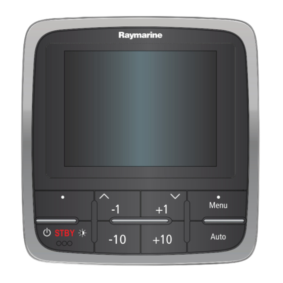
Description DOWN BUTTON / +1 Pilot controls Down navigation, Adjust Down, Increase angle. Control layout and functions. RIGHT SOFT BUTTON p70 8–button pilot controller Menu, Select, OK, Save. STANDBY BUTTON Disengage pilot, Manual control, Power, Brightness. –10 BUTTON Decrease angle. -
Page 38: Powering The Pilot Controller On
Increase angle (locked heading), Note: The Raymarine logo is not displayed if the unit is in ’sleep adjust numerical values, power steer. mode’, the unit may appear off but still has power. -
Page 39: Using The Set Up Wizard
Note: You cannot power down the pilot controller whilst in AUTO mode. Note: If the p70 / p70r is being added to an existing autopilot system already containing a SeaTalk pilot controller then the set up information will be set automatically to reflect existing settings. -
Page 40: Dockside Calibration
2. From the Drive type menu highlight and select your drive type: updated. Note: If your drive type is not listed, contact your Raymarine You can cancel Dockside calibration at any time by pressing STANDBY. - Page 41 2. Disengage any rudder drive clutch. 2. From the Drive settings menu: Main menu > Set up > Auto pilot calibration > Drive settings highlight Hard over time 3. Press CONTINUE. and press SELECT. 4. Check it is safe to proceed before pressing OK. 3.
-
Page 42: Dealer Settings
The water must be calm, with light or no wind. Leave plenty of room to maneuver. 1. Using the UP and DOWN buttons, or the ROTARY controller, highlight Seatrial calibration and press CONTINUE. p70 / p70r Pilot controller Installation instructions... - Page 43 If you still find a deviation of more than 15 degrees, contact your Raymarine dealer for advice. If the deviation is within acceptable limits, press CONTINUE. You can cancel Seatrial calibration at any time by pressing STANDBY.
- Page 44 Caution: Autolearn Please ensure sufficient free space ahead. (Minimum 100x500m long & significantly more for a high speed vessel. Performing autolearn 1. Ensure there is sufficient free water in front of the vessel. p70 / p70r Pilot controller Installation instructions...
-
Page 45: Checking Autopilot Operation
5.8 Checking autopilot operation Item Description Rudder gain too low After completing calibration, check the basic autopilot operation, as follows: Rudder gain too High 1. Steer onto a compass heading and hold a steady course at Correct rudder gain normal cruising speed. If necessary, steer the vessel manually for a short time to check how the vessel steers. - Page 46 If the autopilot: • Gives unstable course keeping and the vessel ‘snakes’ around the desired course, decrease the AutoTrim level. • Hangs off course for excessive periods of time, increase the AutoTrim level. p70 / p70r Pilot controller Installation instructions...
-
Page 47: Chapter 6 Adjust Settings
Chapter 6: Adjust settings Chapter contents • 6.1 Vessel Settings on page 48 • 6.2 Drive settings on page 49 • 6.3 Sailboat settings on page 53 • 6.4 User Settings on page 54 • 6.5 Set up menu on page 55 Adjust settings... -
Page 48: Vessel Settings
• Power cruiser 3 — vessels the SmartPilot system will use capable of speeds greater the cruise speed value you set than 30 knots. here as a default when adjusting autopilot settings. • Sport fishing. p70 / p70r Pilot controller Installation instructions... -
Page 49: Drive Settings
6.2 Drive settings Item Description Options Auto Auto release allows you to • Enable (default) Vessel settings can be accessed from Main menu > Set up > Auto release override the pilot by taking hold pilot calibration > Drive settings. •... - Page 50 MUST ensure that adequate provision is made to prevent the steering mechanism from impacting the endstops. Rudder This specifies the offset from • 0 (default) offset amidships (zero adjustment). p70 / p70r Pilot controller Installation instructions...
- Page 51 Item Description Limits Item Description Limits Reverse This reverses the phase of the • Port Auto trim The AutoTrim setting Setting rudder ref determines the rate at which rudder reference display. • Starboard • Off the SmartPilot system applies Note: This option is ‘standing helm’...
- Page 52 • 10 seconds (default) This can lead to a rough critical importance to set the hard over time, to ensure passage in open waters as the SPX system may ‘fight’ accurate autopilot operation. the sea. p70 / p70r Pilot controller Installation instructions...
-
Page 53: Sailboat Settings
6.3 Sailboat settings Caution: Drive setting adjustments Adjustments to the drive settings will require you to These settings are only available to sailboats. re-calibrate the system. Sailboat settings can be accessed from Main menu > Set up > Auto pilot calibration > Sailboat settings. Note: When connected to a SeaTalk system the Sailboat settings listed below are part of the User settings menu, Main menu >... -
Page 54: User Settings
Wind trim This option determines whether • True type the vessel steers to apparent or • Apparent true wind in Wind Vane mode. Note: These features are only available if wind data is available. p70 / p70r Pilot controller Installation instructions... -
Page 55: Set Up Menu
6.5 Set up menu Menu item Description Options Simulator Enables or disables • On The set up menu provides a range of tools and settings to configure simulator mode, the pilot controller. • Off which allows you to Menu item Description Options practice operating your... -
Page 56: System Setup Menu
This enables you to synchronize the displays Sync brightness / color brightness and color to be the same as the other units • This display in the same network group. • This group p70 / p70r Pilot controller Installation instructions... -
Page 57: User Preferences Menu
Menu item Description Options Multiple data sources This allows you to view and select preferred data Select data source sources. • GPS position • Select data source • Heading • Data source found • Depth • Data source details • Speed •... - Page 58 • Pressure • Bar — bar. • ft — Feet • Volume • kpa — Kilo pascals. • fa—Fathoms • Barometric Volume: • m— Metres • Gal — (US) — US Wind speed: gallons. p70 / p70r Pilot controller Installation instructions...
- Page 59 Menu item Description Options Menu item Description Options Language Determines the • Chinese • Gal — (UK) — UK language that will be gallons. • Croatian used for all on-screen • ltr — litre. text, labels, menus and • Danish options.
- Page 60 • Catamaran • Workboat • RIB • Outboard speed boat • Inboard speed boat • Power cruiser 1 • Power cruiser 2 • Power cruiser 3 • Sport fishing • Pro fishing p70 / p70r Pilot controller Installation instructions...
- Page 61 Diagnostics You can access diagnostics details from the Setup > Diagnostics menu option and can view information relating to: Menu item Description Options About display Allows you to view information about the instrument • Software version display you are using: •...
- Page 62 • Off Self test The product has a built in self test which can help • Memory test to diagnose faults. • Button test • Display test • Buzzer test • Illumination test p70 / p70r Pilot controller Installation instructions...
-
Page 63: Chapter 7 Troubleshooting
Chapter 7: Troubleshooting Chapter contents • 7.1 Troubleshooting on page 64 • 7.2 Power up troubleshooting on page 65 • 7.3 System data troubleshooting on page 66 • 7.4 Miscellaneous troubleshooting on page 67 Troubleshooting... -
Page 64: Troubleshooting
All Raymarine products are, prior to packing and shipping, subjected to comprehensive test and quality assurance programs. However, if you experience problems with the operation of your product this section will help you to diagnose and correct problems in order to restore normal operation. -
Page 65: Power Up Troubleshooting
7.2 Power up troubleshooting Problems at power up and their possible causes and solutions are described here. Problem Possible causes Possible solutions Power supply problem. The system (or part of it) does not start up. Check relevant fuses and breakers. Check that the power supply cable is sound and that all connections are tight and free from corrosion. -
Page 66: System Data Troubleshooting
Check the status of the SeaTalk Switch. Check that SeaTalk cables are free from damage. Software mismatch between equipment Contact Raymarine technical support may prevent communication. p70 / p70r Pilot controller Installation instructions... -
Page 67: Miscellaneous Troubleshooting
Ensure that the front bezel is fitted correctly and that all buttons are free to operate correctly. Software mismatch on system (upgrade Go to www.raymarine.com and click on support for the latest software required). downloads. Corrupt data / other unknown issue. - Page 68 / p70r Pilot controller Installation instructions...
-
Page 69: Chapter 8 Technical Support
Chapter 8: Technical support Chapter contents • 8.1 Raymarine customer support on page 70 • 8.2 Viewing product information on page 70 Technical support... -
Page 70: Raymarine Customer Support
Raymarine provides a comprehensive customer support service. 1. From the main menu scroll to Set Up and press the SELECT key. You can contact customer support through the Raymarine website, 2. From the Set Up menu scroll to Diagnostics and press the telephone and email. -
Page 71: Chapter 9 Technical Specification
Chapter 9: Technical specification Chapter contents • 9.1 Technical specification on page 72 Technical specification... -
Page 72: Technical Specification
TFT LCD display, 16bit color (64k colors) Resolution: 320x240 Brightness: 700 cd/m Data connections 2 x SeaTalk ports (fulling compliant with NMEA2000 & SeaTalk specifications). Conformance • Europe 2004/108/EC • Australia and New Zealand C-Tick, compliance level 2 p70 / p70r Pilot controller Installation instructions... -
Page 73: Chapter 10 Options And Accessories
Chapter 10: Options and accessories Chapter contents • 10.1 SeaTalk cables and accessories on page 74 • 10.2 Converters on page 75 • 10.3 SeaTalk accessories on page 75 • 10.4 Spares and accessories on page 76 Options and accessories... -
Page 74: Seatalk Ng Cables And Accessories
5 m (16.4 ft) A80001 SeaTalk Inline spur terminator SeaTalk 0.4 m (1.3 ft) A06033 SeaTalk Blanking plug A06032 backbone SeaTalk 1 m (3.3 ft) A06034 backbone SeaTalk 3 m (9.8 ft) A06035 backbone p70 / p70r Pilot controller Installation instructions... -
Page 75: Converters
10.2 Converters 10.3 SeaTalk accessories SeaTalk cables and accessories for use with compatible products. Part number Description Description Part No Notes E22158 SeaTalk to SeaTalk Converter NMEA / SeaTalk E85001 converter 3 m (9.8 ft) SeaTalk D285 extension cable 5 m (16.4 ft) SeaTalk D286 extension cable 9 m (29.5 ft) SeaTalk... -
Page 76: Spares And Accessories
10.4 Spares and accessories Part number Description R22168 Spare bezel R22169 p70 Sun cover R22174 p70r Sun cover p70 / p70r Pilot controller Installation instructions... - Page 77 Owner notes:...
- Page 78 Owner notes:...
- Page 80 www.ra ym a rin e .c o m...
Need help?
Do you have a question about the P70 and is the answer not in the manual?
Questions and answers