
Related Manuals for Hatz 1D42


Summary of Contents for Hatz 1D42
- Page 1 Translation of the ORIGINAL INSTRUCTION BOOK 1D 42. 1D 50. 1D 81. 1D 90. 0000 433 216 11-USA-EPA IV-CARB 01.12-0.1 Printed in Germany...
- Page 2 HATZ spare parts and HATZ tools. The world-wide HATZ service network is also available to you for consultation and spare parts supply. For the address of your nearest HATZ service station, please refer to the attached list or the internet under: www.hatz-diesel.com The installation of inappropriate spare parts may cause problems.
-
Page 3: Table Of Contents
Contents Page Page Important notes on safe operation 5.3. Maintenance every 250 hours of the engine of operation 5.3.1. Oilbath air cleaner maintenance Description of engine 5.3.2. Changing engine oil, renewing General information oil filter 3.1. Technical data 5.3.3. Checking and adjusting 3.2. -
Page 4: Important Notes On Safe Operation Of The Engine
Important notes on safe operation of the engine HATZ diesel engines are economical, strongly built and long-lasting. They are therefore frequently chosen for commercially and industrially operated equipment and machinery. Since the engine forms part of the finished equipment or machine, its manufacturer will take all the applicable safety regulations into account. - Page 5 Regular servicing in accordance with the details provided in this Instruction Book is essential to keep the operating reliably and to ensure the exhaust quality of the engine. In case of doubt, always consult your nearest HATZ service station before starting the engine.
-
Page 6: Description Of Engine
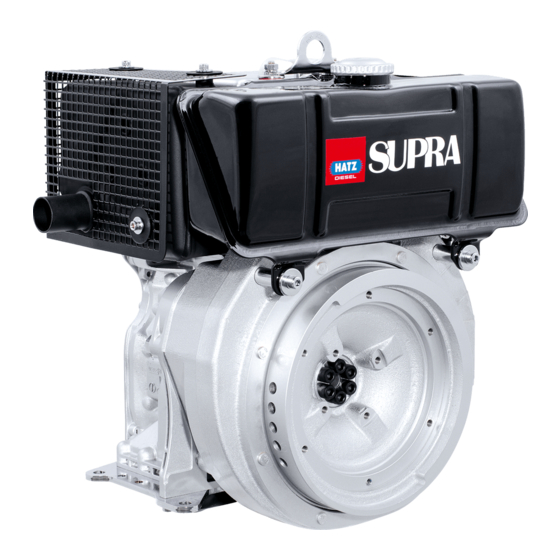
Description of engine 1D42 • 1D50 • 1D81 • 1D90 S / Z engines 2391 / 12 2391 / 7 1 Cooling air inlet 11 Tank filler cap 2 Dry-type air cleaner 12 Oil drain plug, governor housing 3 Decompression lever... - Page 7 Description of engine Fully-encapsulated version 1D42C • 1D81C engines 2392 / 1 2392 / 4 1 Capsule 10 Silencer (muffler), encapsul. 2 Decompression lever 11 Cooling air outlet 3 Cold-start oil metering device 12 Battery connection and central plug 4 Combustion and cooling air intake for electrical system 5 Oil filter 13 Stop lever...
-
Page 8: General Information
General information 3.1. Technical data Type 1D42. 1D50. 1D81. 1D90. Engine models S, Z, C S, Z S, Z, C S, Z Mode of operation air-cooled four-stroke diesel engine Combustion method Direct-fuel injection Number of cylinders Bore / stroke 90 / 70... -
Page 9: Transport
The permitted loads and elements on portant information about safe assembly of the the speed adjusting lever and the stop engine and are available from your the HATZ lever should be observed as an exess can lead service center in your area. -
Page 10: Epa / Carb - Type Plates
3.5. EPA/CARB-type plates and Every engine is equipped with an additional loose engine type plate. If the original type fuel label plate on the engine is not readily visible after The layout of the EPA / CARB - type plate depends the engine is installed in the equipment then on the engine application and is placed on the the second loose type plate must be attached... -
Page 11: Operation
The engine must be in a horizontal position be- Operation fore adding oil or checking the oil level. 4.1. Before initial start-up Engines are normally delivered without fuel and oil. 4.1.1. Engine oil Qualified are all trademark oils which fulfil at least one of the following specifications: ACEA –... -
Page 12: Fuel
The use of fuels of different specifications re- on the fuel feed pump until fuel is heard to quires the prior written consent of the HATZ flow back to the tank through the return line. headquarters. -
Page 13: Mechanical Oil Pressure Monitor
At temperatures below 0 °C, winter-grade fuel should be used or parafin added to the fuel well in advance. Paraffin content for: Lowest ambient temperature when Summer Winter starting, in °C fuel fuel 0 up to –10 20 % – –10 up to –15 30 % –... -
Page 14: Starting The Engine
0000 051 268 02 Instructions to activate the mechanical oil pres- WARNING sure control are mentioned on the sticker placed on the engine. Risk of serious injury from rotating parts. Never put your hands in the guide sleeve of the IMPORTANT ! cranking device while the engine is running. -
Page 15: Preparations For Starting
4.2.1. Preparations for starting – If possible, disengage the engine from any driven equipment. The auxiliary equipment should always be placed in neutral. START STOP START 2292 / 6 – Turn the decompression lever until stop „1“ is STOP reached. In this position the automatic decom- pression system is heard to engage and the engine can then be started;... -
Page 16: Starting With The Handle
4.2.2. Starting with the handle – Turn the handle slowly until the pawl engages in the ratchet, then increase turning force to For preparations to start the engine, build up speed. The highest speed must have see Chapter 4.2.1. been reached when the decompression lever returns to the „0“... -
Page 17: Starting In Cold Weather
– Take hold of the starting handle with both hands and turn it at increasing speed. The maximum speed of rotation must have been reached by the time the decompression lever has returned to the „0“ position (compres- sion). As soon as the engine has started, pull the starting handle out of the guide sleeve. -
Page 18: Electric Starter
4.2.4. Electric starter – Always turn the start key back to position 0 before re-starting the engine. The repeat lock For preparations to start, see Chapter 4.2.1. in the ignition lock prevents the starter motor from engaging and possibly being damaged –... -
Page 19: Stopping The Engine
Automatic electrical shutdown system 4.3. Stopping the engine (additional equipment) Never stop the engine by moving the decompression lever. During breaks This is characterized by a brief flashing of all in work or at the conclusion of the working pe- pilot lamps once the starter key has been turned riod, keep the starting handle and starting key to position I (Fig. - Page 20 – On engines with the lower engine speeds not accessible, move speed control lever „1“ back, then move stop lever „2“ in the STOP direction. Hold it there until the engine has stopped. – Once the engine is not running any longer, release the stop lever.
-
Page 21: Maintenance
Maintenance The engine must be stopped before any maintenance work is attempted. Comply with legal requirements when handling and disposing of old oil, filters and cleaning materials. Keep the engine’s starting key and starting handle out of reach of unauthorized persons. To immobilize engines with an electric starter, disconnect the negative battery terminal. - Page 22 1D41: IN 0.1 mm EX 0.2 mm 1D42: IN 0.1 mm EX 0.2 mm 1D50: IN 0.1 mm EX 0.2 mm 1D81: IN 0.1 mm EX 0.2 mm DIESEL 1D90: IN 0.3 mm EX 0.3 mm 1D.. 250h = 1h...
-
Page 23: Maintenance Every 8 - 15 Hours Of Operation
8 – 15 5.2. Maintenance every hours of operation 5.2.1. Check engine oil level When checking the oil level, the engine should be standing level, and must not be running. – Remove any dirt in the dipstick area. 2393 / 10 –... -
Page 24: Checking Cooling Air Zone
5.2.4. Checking cooling air zone – Trap the drops which emerge in a transparent vessel. Since water has a greater specific grav- Severe contamination is a sign that there are ity than diesel fuel, the water emerges before large amounts of dust in the atmosphere and the diesel fuel. -
Page 25: Maintenance Every 250 Hours Of Operation
– Sealing package acc. picture 35 is mounted at – Take off the oil reservoir „1“ and clean it. engines 1D41, 1D42 and 1D50. – Remove contaminated oil and sludge from the oil tank, and clean it out. -
Page 26: Changing Engine Oil, Renewing Oil Filter
5.3.2. Changing engine oil, Fully encapsulated engines: renewing oil filter The engine must be stopped, and should stand on a flat, level surface. Drain the engine oil only when it is warm. For oil drain plug, see Chapter 2. Risk of scalding from hot oil. Catch waste oil and dispase acc. -
Page 27: Checking And Adjusting Valve Clearances
5.3.3. Checking and adjusting valve clearances – Move the decompression lever to position „0“; Fig. 17 and 18. – Clean sieve bottom carefully in order not to bend the netting. Wipe out cap screw or blow it out with com- pressed air. -
Page 28: Clean The Cooling Air System
– Turn the engine over in the normal direction of rotation until compression is felt. – In case of the enclosed design, place the lever for decompression „1“ in horizontal position. Then, mount the cover of the enclosure in the order 2...3. -
Page 29: Checking Threaded Connections
2396 / 3 – Trace the cause of any contamination with oil and have the leak eliminated by a HATZ service station. Adjustment screws on speed governor and injection system are painted with –... -
Page 30: Maintenance Every 500 Hours Of Operation
5.4. Maintenance every hours of operation 5.4.1. Renewing fuel filter Fuel filter maintenance intervals depend on the purity of the fuel used; reduce them to 250 hours of operation if necessary. Do not smoke or bring a naked flame near the fuel system when working on it. -
Page 31: Dry-Type Air Cleaner Maintenance
– Activate mechanical oil pressure monitor (optional extra), chap. 4.1.4. – Run the engine briefly to check the fuel filter and lines for leaks. 5.4.2. Dry-type air cleaner maintenance It is best to clean the filter cartridge only when the maintenance indicator displays the appropri- ate signal. - Page 32 Cleaning the filter cartridge Dry contamination – In case of the enclosed design, place the lever 2281 / 5 for decompression „1“ in horizontal position. Then, mount the cover of the enclosure in the – Blow through the filter cartridge from the in- order 2...3.
-
Page 33: Malfunctions - Causes - Remedies
Malfunctions – Causes – Remedies Malfunction Possible causes Remedial action Chap. Engine will not Speed control lever is in stop or start or start is idle position. delayed, although Stop lever in stop position. Set lever to „START“-position 4.2. it can be turned over with the No fuel reaching injection pump. - Page 34 - Battery and/or other wiring is Check electrical system incl. not turned over. wrongly connected. indiv. components or contact a - Wiring connections loose HATZ-service station. and/or corroded. - Battery defective and/or flat. - Defective starter motor - Defective relays, monitoring elements etc.
- Page 35 Activate mechanical oil pressure pressure. monitor. 4.1.4. Mechanical defects. Contact a HATZ-service station. In addition, if auto- Stop signal from monitoring matic engine shut- element because of: Check engine for: down is installed.
- Page 36 Malfunction Possible causes Remedial action Chap. Low engine power, Fuel supply is obstructed: output and speed. - Tank run dry. Add fuel. 4.1.3. 4.1.4. - Fuel filter blocked. Renew fuel filter. 5.4.1. - Tank venting is inadequate Ensure that tank is adequately vented.
-
Page 37: Work On The Electrical System
HATZ assumes no liability for electrical systems – The positive (+) and negative (–) battery ter- which was not carried out acc. HATZ circuit dia- minals must not be accidentally interchanged. grams. – When installing the battery, connect the posi- tive lead first, followed by the negative lead. -
Page 40: Supplemental Information To The Owner's Manual For Model Year 2012 Epa Certified Nonroad Compression Ignition Engines
SUPPLEMENTAL INFORMATION TO THE OWNER'S MANUAL FOR MODEL YEAR 2012 EPA CERTIFIED NONROAD COMPRESSION IGNITION ENGINES. EPA EMISSION CONTROL SUPPLEMENTAL WARRANTY STATEMENT AND EMISSION-RELATED INSTALLATION INSTRUCTIONS. - Page 41 ENGINE PARTS AND / OR EQUIPMENT RELATED TO EPA EXHAUST EMISSION REGULATIONS. Parts which are mandatory for engine operation. The following parts as manufactured according to HATZ specifications are mandatory for engine operation which meets EPA exhaust emission regulations. • Fuel injection pump •...
- Page 42 • Oil filler cap • Intake and exhaust gaskets at head interfaces • Emission Control Information Labels Only parts manufactured by Hatz and which have passed the Hatz Quality Assurance Program are assured of meeting EPA exhaust emission regulations. UNUSUAL OPERATING CONDITIONS.
- Page 43 Therefore, the maintenance work has to be carried out by a qualified workshop. Hatz authorised workshops, for example, are qualified workshops. Hatz Diesel of America will give you respective addresses, if required. EMISSION CONTROL SYSTEM AND ADJUSTMENTS. The emission control system for this engine is DI (Direct Injection) and EM (Engine Modification).
- Page 44 EPA EMISSION CONTROL WARRANTY STATEMENT YOUR WARRANTY RIGHTS AND OBLIGATIONS. Motorenfabrik Hatz GmbH & Co. KG warrants the emission control system on your engine for the periods of time listed below provided there has been no abuse, neglect or improper maintenance of your engine.
-
Page 45: Manufacturers Warranty Coverage
• As the engine owner, you should be aware, however, that Motorenfabrik Hatz may deny you warranty coverage if your engine or a part has failed due to abuse, neglect, improper maintenance or unapproved modifications. - Page 46 PARTS WITH SUPPLEMENTAL LIMITED WARRANTY. The following limited warranty is supplemental to the standard HATZ DIESEL LIMITED ENGINE WARRANTY and covers Model Year 2012 EPA certified engines and applies to the following exhaust emission-related components: • Fuel injection pump • Injection nozzle •...
- Page 47 Hatz Diesel of America, Inc. hereinafter referred to as “HATZ” warrants each of the above-listed parts when installed in a new engine sold by Hatz to be free from defects in material and workmanship under normal use and service, only under the named warranty...
- Page 48 EMISSION-RELATED INSTALLATION INSTRUCTIONS “Failing to follow these instructions when installing a certified engine in a piece of nonroad equipment violates federal law (40CFR1068.105(b)), subject to fines or other penalties as described in the Clean Air Act.” “If you install the engine in a way that makes the engine's emission control information labels hard to read during normal engine maintenance, you must place duplicate labels on the equipment.”...
- Page 49 INSTRUCTIONS ON THE INSTALLATION OF THE EXHAUST SYSTEM Following are the instructions to properly install the exhaust system and related components consistent with the EPA emission regulation requirements. 1D42 · 1D50 · 1D81 · 1D90 S / Z 23 Nm 17 lb ft Exhaust-silencers and protection guard The exhaust silencer is fitted in connection with studs, flat washers and hex.-nuts.
- Page 50 Dismantling: • Remove in numerical sequence 1...4 (C). • For opening screws 1 a special tool is required (HATZ-Ident Nr. 630 815 00). Assembly: • Assemble in reverse sequence. • Apply lubricant as specified by HATZ.
- Page 51 1D42 C · 1D81 C Encapsulated engine Before dismantling the exhaust system the capsule has to be dismounted: • Remove the four screws (2) of the top cover (3). • Remove the side cover (1) by opening the two clips.
- Page 52 Assembly: • Assemble in reverse sequence. • Apply lubricant as specified by HATZ. • Torque to specification! • Before tightening the capsule all screws have to be turned in and the different covers have to be correctly adjusted.
- Page 53 1D42 C · 1D81 C Sequence of dismantling the exhaust system: • Open screws (1) and (2) and remove with shims. • Remove big silencer with attached sealing gaskets (3). • Open screws (4) and remove with shims. • Remove silencer (5) with attached sealing gaskets (6).
- Page 54 Assembly: • Assemble in reverse sequence. • Apply lubricant as specified by HATZ. • Torque to specification ! • Ensure gasket-kit is fitted in correct sequence i.e. the creased gaskets (6) face towards exhaust silencer. • Make sure that all parts are correctly placed and tightened.
- Page 55 Engine type Ø d (mm) HATZ-Ident. Nr. HATZ-Ident. Nr. HATZ-Ident. Nr. 039 973 01 830 860 00 503 880 00 1D42 S / Z 830 857 00 830 858 00 037 409 00 039 973 01 830 860 00 503 880 00...
-
Page 56: To The Owner's Manual For
SUPPLEMENTAL INFORMATION TO THE OWNER´S MANUAL FOR MODEL YEAR 2012 CALIFORNIA REGULATIONS FOR HEAVY-DUTY OFF-ROAD ENGINES. CALIFORNIA EMISSION CONTROL WARRANTY STATEMENT AND EMISSION-RELATED INSTALLATION INSTRUCTIONS. - Page 57 ENGINE PARTS AND / OR EQUIPMENT RELATED TO CARB EXHAUST EMISSION REGULATIONS. Parts which are mandatory for engine operation. The following parts as manufactured according to HATZ specifications are mandatory for engine operation which meets CARB exhaust emission regulations. • Fuel injector •...
- Page 58 • Oil filler Cap • Intake and exhaust gaskets at head interfaces • Emission Control Information Labels Only parts manufactured by Hatz and which have passed the Hatz Quality Assurance Program are assured of meeting CARB exhaust emission regulations. UNUSUAL OPERATING CONDITIONS.
- Page 59 CALIFORNIA EMISSION CONTROL SYSTEM WARRANTY STATEMENT. YOUR WARRANTY RIGHTS AND OBLIGATIONS. The California Air Resources Board and Motorenfabrik Hatz GmbH & Co. KG are pleased to explain the emission control system warranty on your Model Year 2012 engine. In California, new heavy-duty off-road engines must be designed, built, and equipped to meet the State’s stringent anti-smog standards.
- Page 60 • As the heavy-duty off-road engine owner, you are responsible for the performance of the required maintenance listed in your owner’s manual. Motorenfabrik Hatz GmbH & Co. KG recommends that you retain all receipts covering maintenance on your heavy-duty off-road engine, but Motorenfabrik Hatz GmbH & Co.
- Page 61 CALIFORNIA CERTIFIED HEAVY-DUTY OFF-ROAD ENGINES. PARTS WITH SUPPLEMENTAL LIMITED WARRANTY. The following limited warranty is supplemental to the standard HATZ DIESEL LIMITED ENGINE WARRANTY and covers Model Year 2012 California certified Heavy-Duty off- road engines and applies to the following exhaust emission-related components: •...
- Page 62 Hatz Diesel of America, Inc. hereinafter referred to as "HATZ" warrants each of the above-listed parts when installed in a new engine sold by Hatz to be free from defects in material and workmanship under normal use and service, for a period of twenty-four (24)
- Page 63 EMISSION-RELATED INSTALLATION INSTRUCTIONS “Failing to follow these instructions when installing a certified engine in a piece of nonroad equipment violates federal law (40CFR1068.105(b)), subject to fines or other penalties as described in the Clean Air Act.” “If you install the engine in a way that makes the engine's emission control information labels hard to read during normal engine maintenance, you must place duplicate labels on the equipment.”...
- Page 64 INSTRUCTIONS ON THE INSTALLATION OF THE EXHAUST SYSTEM Following are the instructions to properly install the exhaust system and related components consistent with the CARB emission regulation requirements. 1D42 · 1D50 · 1D81 · 1D90 S / Z 23 Nm 17 lb ft Exhaust-silencers and protection guard The exhaust silencer is fitted in connection with studs, flat washers and hex.-nuts.
- Page 65 Dismantling: • Remove in numerical sequence 1...4 (C). • For opening screws 1 a special tool is required (HATZ-Ident Nr. 630 815 00). Assembly: • Assemble in reverse sequence. • Apply lubricant as specified by HATZ.
- Page 66 1D42 C · 1D81 C Encapsulated engine Before dismantling the exhaust system the capsule has to be dismounted: • Remove the four screws (2) of the top cover (3). • Remove the side cover (1) by opening the two clips.
- Page 67 Assembly: • Assemble in reverse sequence. • Apply lubricant as specified by HATZ. • Torque to specification! • Before tightening the capsule all screws have to be turned in and the different covers have to be correctly adjusted.
- Page 68 1D42 C · 1D81 C Sequence of dismantling the exhaust system: • Open screws (1) and (2) and remove with shims. • Remove big silencer with attached sealing gaskets (3). • Open screws (4) and remove with shims. • Remove silencer (5) with attached sealing gaskets (6).
- Page 69 Assembly: • Assemble in reverse sequence. • Apply lubricant as specified by HATZ. • Torque to specification ! • Ensure gasket-kit is fitted in correct sequence i.e. the creased gaskets (6) face towards exhaust silencer. • Make sure that all parts are correctly placed and tightened.
- Page 70 Engine type Ø d (mm) HATZ-Ident. Nr. HATZ-Ident. Nr. HATZ-Ident. Nr. 039 973 01 830 860 00 503 880 00 1D42 S / Z 830 857 00 830 858 00 037 409 00 039 973 01 830 860 00 503 880 00...
- Page 71 CALIFORNIA Proposition 65 Warning Diesel engine exhaust and some of its constituents are known to the State of California to cause cancer, birth defects, and other reproductive harm.
Need help?
Do you have a question about the 1D42 and is the answer not in the manual?
Questions and answers