
Related Manuals for Hatz 1D41.


Summary of Contents for Hatz 1D41.
- Page 1 Translation of the ORIGINAL INSTRUCTION BOOK 1D 41. 1D 42. 1D 50. 1D 81. 1D 90. 0000 433 202 09 - ENG - 12.09 - 3 Printed in Germany...
- Page 2 HATZ spare parts and HATZ tools. The world-wide HATZ service network is also available to you for consultation and spare parts supply. For the address of your nearest HATZ service station, please refer to the attached list or the internet under: www.hatz-diesel.com The installation of inappropriate spare parts may cause problems.
-
Page 3: Table Of Contents
Contents Page Page Important notes on safe operation 5.3. Maintenance every 250 hours of the engine of operation 5.3.1. Oilbath air cleaner maintenance Description of the engine 5.3.2. Changing engine oil, renewing oil filter General information 5.3.3. Checking and adjusting 3.1. -
Page 4: Important Notes On Safe Operation Of The Engine
Important notes on safe operation of the engine HATZ diesel engines are economical, strongly built and long-lasting. They are therefore frequently chosen for commercially and industrially operated equipment and machinery. Since the engine forms part of the finished equipment or machine, its manufacturer will take all the applicable safety regulations into account. - Page 5 – Note that any unauthorized modification to the engine absolves its manufacturer from liability for the consequences. Regular servicing in accordance with the details provided in this Instruction Book is essential to keep the engine operating reliably. In case of doubt, always consult your nearest HATZ service station before starting the engine.
-
Page 6: Description Of The Engine
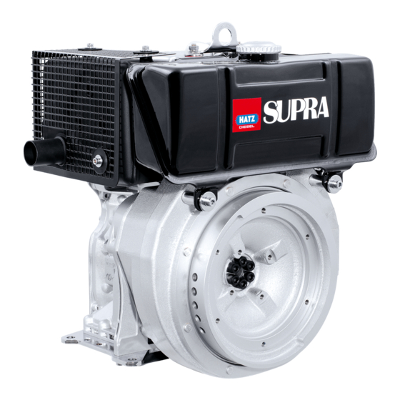
Description of engine 1D41 • 1D42 • 1D50 • 1D81 • 1D90 S / Z engines 2391 / 12 2391 / 7 1 Cooling air inlet 11 Tank filler cap 2 Dry-type air cleaner 12 Oil drain plug, governor housing 3 Decompression lever 13 Oil drain plug, governor side 4 Stop lever... - Page 7 Description of engine Fully-encapsulated version 1D41C • 1D42C • 1D81C • 1D90 C engines 2392 / 1 2392 / 4 1 Capsule 10 Silencer (muffler), encapsul. 2 Decompression lever 11 Cooling air outlet 3 Cold-start oil metering device 12 Battery connection and central plug 4 Combustion and cooling air intake for electrical system 5 Oil filter...
-
Page 8: General Information
General information 3.1. Technical data Type 1D41. 1D42. 1D50. 1D81. 1D90. Engine models S, Z, C S, Z, C S, Z S, Z, C S, Z, C Mode of operation air-cooled four-stroke diesel engine Combustion method Direct-fuel injection Number of cylinders Bore / stroke 90 / 65 90 / 70... -
Page 9: Transport
You can obtain a copy of this manual from your nearest HATZ ➀ ➁ service station. -
Page 10: Operation
The engine must be in a horizontal position be- Operation fore adding oil or checking the oil level. 4.1. Before initial start-up Engines are normally delivered without fuel and oil. 4.1.1. Engine oil Qualified are all trademark oils which fulfil at least one of the following specifications: ACEA –... -
Page 11: Fuel
The use of fuels of different specifications re- on the fuel feed pump until fuel is heard to quires the prior written consent of the HATZ flow back to the tank through the return line. headquarters. -
Page 12: Mechanical Oil Pressure Monitor
At temperatures below 0 °C, winter-grade fuel should be used or parafin added to the fuel well in advance. Paraffin content for: Lowest ambient temperature when Summer Winter starting, in °C fuel fuel 0 up to –10 20 % – –10 up to –15 30 % –... -
Page 13: Starting The Engine
0000 051 268 02 Instructions to activate the mechanical oil pres- Do not enter the guide sleeve of sure control are mentioned on the sticker placed the starting device whilst engine on the engine. is running - risk of injury ! IMPORTANT ! Even with mechanical oil pressure monitoring the oil level must be checked every 8 –... -
Page 14: Preparations For Starting
4.2.1. Preparations for starting – If possible, disengage the engine from any driven equipment. The auxiliary equipment should always be placed in neutral. START STOP START 2292 / 6 – Turn the decompression lever until stop „1“ is STOP reached. In this position the automatic decom- pression system is heard to engage and the engine can then be started;... -
Page 15: Starting With The Handle
4.2.2. Starting with the handle – Turn the handle slowly until the pawl engages in the ratchet, then increase turning force to For preparations to start the engine, build up speed. The highest speed must have see Chapter 4.2.1. been reached when the decompression lever returns to the „0“... -
Page 16: Starting In Cold Weather
– Take hold of the starting handle with both hands and turn it at increasing speed. The maximum speed of rotation must have been reached by the time the decompression lever has returned to the „0“ position (compres- sion). As soon as the engine has started, pull the starting handle out of the guide sleeve. -
Page 17: Electric Starter
4.2.4. Electric starter – Always turn the start key back to position 0 before re-starting the engine. The repeat lock For preparations to start, see Chapter 4.2.1. in the ignition lock prevents the starter motor from engaging and possibly being damaged –... -
Page 18: Stopping The Engine
Automatic electrical shutdown system 4.3. Stopping the engine (additional equipment) Never stop the engine by moving the decompression lever. During breaks This is characterized by a brief flashing of all in work or at the conclusion of the working pe- pilot lamps once the starter key has been turned riod, keep the starting handle and starting key to position I (Fig. - Page 19 – On engines with the lower engine speeds Electrical system not accessible, move speed control lever „1“ back, then move stop lever „2“ in the STOP direction. Hold it there until the engine has stopped. – Once the engine is not running any longer, release the stop lever.
-
Page 20: Maintenance
Maintenance The engine must be stopped before any maintenance work is attempted. Comply with legal requirements when handling and disposing of old oil, filters and cleaning materials. Keep the engine’s starting key and starting handle out of reach of unauthorized persons. To immobilize engines with an electric starter, disconnect the negative battery terminal. - Page 21 The above maintenance chart is supplied with For new or reconditioned engines, the following every engine. This label should be affixed to the must always be carried out after first 25 operat- engine or equipment in an easily visible position. ing hours: The maintenance chart governs the maintenance intervals.
-
Page 22: Maintenance Every 8 - 15 Hours Of Operation
8 – 15 5.2. Maintenance every hours of operation 5.2.1. Check engine oil level When checking the oil level, the engine should be standing level, and must not be running. – Remove any dirt in the dipstick area. 2393 / 10 –... -
Page 23: Checking Cooling Air Zone
5.2.4. Checking cooling air zone – Trap the drops which emerge in a transparent vessel. Since water has a greater specific Severe contamination is a sign that there are gravity than diesel fuel, the water emerges be- large amounts of dust in the atmosphere and fore the diesel fuel. -
Page 24: Maintenance Every 250 Hours Of Operation
– If the sealing face is uneven, the air cleaner 5.3. Maintenance every body cracked and/or the filter wool content is hours of operation incomplete, install a new air cleaner. 5.3.1. Oil bath air cleaner maintenance – Attach the upper part of the air cleaner with a new flange gasket. -
Page 25: Changing Engine Oil, Renewing Oil Filter
5.3.2. Changing engine oil, Fully encapsulated engines: renewing oil filter The engine must be stopped, and should stand on a flat, level surface. Drain the engine oil only when it is warm. For oil drain plug, see Chapter 2. Risk of scalding from hot oil. Catch waste oil and dispase acc. -
Page 26: Checking And Adjusting Valve Clearances
5.3.3. Checking and adjusting valve clearances – Move the decompression lever to position „0“; Fig. 17 and 18. – Clean sieve bottom carefully in order not to bend the netting. Wipe out cap screw or blow it out with com- pressed air. -
Page 27: Clean The Cooling Air System
– Turn the engine over in the normal direction of rotation until compression is felt. – In case of the enclosed design, place the lever for decompression „1“ in horizontal position. Then, mount the cover of the enclosure in the order 2...3. -
Page 28: Checking Threaded Connections
2396 / 3 – Trace the cause of any contamination with oil and have the leak eliminated by a HATZ service station. Adjustment screws on speed governor and injection system are painted with –... -
Page 29: Maintenance Every 500 Hours Of Operation
5.4. Maintenance every hours of operation 5.4.1. Renewing fuel filter Fuel filter maintenance intervals depend on the purity of the fuel used; reduce them to 250 hours of operation if necessary. Do not smoke or bring a naked flame near the fuel system when working on it. -
Page 30: Dry-Type Air Cleaner Maintenance
– Activate mechanical oil pressure monitor (optional extra), chap. 4.1.4. – Run the engine briefly to check the fuel filter and lines for leaks. 5.4.2. Dry-type air cleaner maintenance It is best to clean the filter cartridge only when the maintenance indicator displays the appropri- ate signal. - Page 31 Cleaning the filter cartridge Dry contamination – In case of the enclosed design, place the lever 2281 / 5 for decompression „1“ in horizontal position. Then, mount the cover of the enclosure in the – Blow through the filter cartridge from the in- order 2...3.
-
Page 32: Malfunctions - Causes - Remedies
Malfunctions – Causes – Remedies Malfunction Possible causes Remedial action Chap. Engine will not Speed control lever is in stop or start or start is idle position. delayed, although Stop lever in stop position. Set lever to „START“-position 4.2. it can be turned over with the No fuel reaching injection pump. - Page 33 - Battery and/or other wiring is Check electrical system incl. not turned over. wrongly connected. indiv. components or contact a - Wiring connections loose HATZ-service station. and/or corroded. - Battery defective and/or flat. - Defective starter motor - Defective relays, monitoring elements etc.
- Page 34 Activate mechanical oil pressure pressure. monitor. 4.1.4. Mechanical defects. Contact a HATZ-service station. In addition, if auto- Stop signal from monitoring matic engine shut- element because of: Check engine for: down is installed.
- Page 35 Malfunction Possible causes Remedial action Chap. Low engine power, Fuel supply is obstructed: output and speed. - Tank run dry. Add fuel. 4.1.3. 4.1.4. - Fuel filter blocked. Renew fuel filter. 5.4.1. - Tank venting is inadequate Ensure that tank is adequately vented.
-
Page 36: Work On The Electrical System
HATZ assumes no liability for electrical systems – The positive (+) and negative (–) battery ter- which was not carried out acc. HATZ circuit dia- minals must not be accidentally interchanged. grams. – When installing the battery, connect the posi- tive lead first, followed by the negative lead. - Page 38 CALIFORNIA Proposition 65 Warning Diesel engine exhaust and some of its constituents are known to the State of California to cause cancer, birth defects, and other reproductive harm.
Need help?
Do you have a question about the 1D41. and is the answer not in the manual?
Questions and answers