Table of Contents
Advertisement
Advertisement
Table of Contents

Summary of Contents for CnM 8 Channel H.264 Digital Video Recorder
-
Page 2: Table Of Contents
CONTENTS 1 INTRODUCTION ............................2 1.1MAIN FEATURES ..........................2 1.2 PRODUCT FEATURES.........................2 1.2.1 PARAMETER ..........................2 1.2.2 BASIC WORKING PARAMETER....................4 1.3 ENTIRONMENT ADAPTABILITY ......................4 2. DEVICE OPERATION MANUAL ........................5 2.1 REMOTE KEY INSTRUCTION ......................5 2.1.1 REMOTE CONTROL........................5 2.1.2 MOUSE OPERATION ........................6 2.1.3 MENU TREE..........................7 2.2 SYSTEM OPERATION ........................8 2.2.1 USER LOGIN..........................8 2.2.2 GUI OPERATION ........................9... -
Page 3: Introduction
1 INTRODUCTION 1.1 MAIN FEATURES This 8 channel Digital Video Recorder (DVR), has local recording and playback as well as supporting: triple code remote network surveillance, data backup, parameter setting and motion detection. 1.2 PRODUCT FEATURES H.264 compression Two USB interfaces, USB2.0 for data backup, USB1.1 for mouse operation. 3.5”... - Page 4 Audio Input 8ch audio input,impedance 600Ω,RCA Audio Audio Output 1ch audio output, impedance 600Ω, RCA Basic electricity output Linear electricity Record style Audio video recorded simultaneously Audio compression ADPCM Picture compression H.264 Picture resolution CIF / HD1 / D1 Streaming style ISO14496-10 Audio style ADPCM...
-
Page 5: Basic Working Parameter
1.2.2 BASIC WORKING PARAMETERS Item Parameter Description Voltage Input DC 19V 12V(+/-0.2) 12V,2A Voltage Output for Camera Video Impedance Input 75Ω 75Ω each channel Video Output 1Vp-p 1Vp-p CVBS signal SATA HDD One SATA with all capability Working temperature -10----50℃ Under normal conditions 1.3 ENTIRONMENT ADAPTABILITY For the safety when using the DVR and to prolong the life of the device, please pay attention on following:... -
Page 6: Device Operation Manual
2. DEVICE OPERATION MANUAL Note: The enter key on the remote control has the same functionality as a click of the left mouse button. 2.1 REMOTE KEY INSTRUCTION 2.1.1 REMOTE CONTROL Handheld Remote Controller Key Functions: 【0-9】keys: During setup, number keys are used to input values. For viewing channels 1, 2, 3, 4, 5, 6, 7 and 8 use 1, 2, 3, 4, 5, 6, 7 and 8 on numeric keypad respectively. -
Page 7: Mouse Operation
2.1.2 MOUSE OPERATION You can use mouse to operate the menu as well as using the IR remote controller. (It operates in the same way as the Windows Operating System does). Please insert the mouse into USB 1.1. Enter into main menu: Click the right mouse button on the live view. Click right button Exit the present menu: It will not save the settings if clicking the right key to exit. -
Page 8: Menu Tree
1. Press the left button to move the mouse, this can adjust the parameter on the volume, color interface. And the corresponding parameter will be displayed at the same time. Mouse move 2. In the Motion Detection setting interface, you can use the left button to drag the frame to set the motion detection area. -
Page 9: System Operation
2.2 SYSTEM OPERATION 2.2.1 USER LOGIN 1. START-UP Connect the DC19V/3A Power Adapter to the DVR. When the DVR has started, the 【POW】 LED will be on and 9 images will be displayed on the screen. If you have setup Power UP recording or Timed Recording, the system will record automatically and the corresponding LED will be on. -
Page 10: Gui Operation
2.2.2 GUI OPERATION The main menu includes “SEARCH”, ”RECORD”, ”HDD”, ”BASIC”, “ADVANCE” and “Exit”. Remark: To change the settings of sub menu items, you must press “APPLY”. It will not save the settings if you exit without saving. This DVR has a special feature: Explanation and information will be showed automatically when you move the cursor over a Menu option. - Page 11 Instruction: MONTH: Will show the recording status in this month. Green means normal recording, Red means alarm recording, Blue means no recording. Clicking any date in this frame will search the recording status of that day, the search results will be shown below in the date frame.. DATE: Will show the recording status in this day, you can playback the recorded files in any period by clicking the corresponding period.
-
Page 12: Backup
2. BACKUP You can use USB to backup recordings too, by inserting a USB device into the USB2.0 port before backing up files. USB OTG (On-The-Go) is also supported. You can select the recording to be backed-up by using the direction keys, pressing【Enter】confirms the selected file (There will be a tick “√”... -
Page 13: Hdd Management
CHANNEL: ON: Means the channel is enabled for recording. QUALITY: There are three options: HIGHEST, HIGH and NORMAL, corresponding to HIGHEST, HIGH and NORMAL data stream standards. AUDIO: ON: Means audio recording for all channels is enabled, OFF: Means audio recording is disabled. REC.MODE: POWER UP: Means the device will start recording when it starts up. -
Page 14: Basic Setup
HDD STATUS: There are three settings available, normal, un-format, No HDD. If the HDD cannot run normally(including un-format and no HDD), there will be a 【H】 displayed on video live view. OVERWRITE: ENABLE: when HDD space is less than 4GB, the earliest recording files will be deleted, files will stop being deleted when the space available has increased to 10GB;... -
Page 15: Date/Time Setup
System language is optional, including Chinese and English. You can choose the language you want. Note: The device will restart when you finish system language setup. 7. DATE/TIME SETUP Move cursor to select “Date/Time” and press 【ENTER】 or click the left mouse button to enter into the Date/Time setup interface. -
Page 16: Display Setup
DEVICE ID: Press number key to setup the ID PASSWORD: Press 【APPLY】 to start or close the user password. If it shows “ENABLE”, you have to input the password when logging in, otherwise, you can access main menu directly. USER PASSWORD: Press number key to setup. ADMIN PASSWORD: Press number key to setup. -
Page 17: Video/Audio Setup
Press 【Enter】 or 【+】 【-】 key or directly drag the bar to setup colors, including chroma, brightness, contrast and saturation, press 【APPLY】 to save the parameters once the setup is completed. PREVIEW: ON: Means the channel is allowed to view the live mode, OFF means not. PREVIEW TIME: ON: Means insert clock in live view, OFF means no clock. -
Page 18: Advanced Setup
11. ADVANCE SETUP Move the cursor to 【ADVANCE SETUP】 (Icon highlighted when selected), press 【Enter】 to enter into Advanced Setup. Picture is below: Advanced Functions include Alarm settings, System information, Motion detection, Mobile phone monitoring, System maintenance, PTZ and Network settings. 12. -
Page 19: System Info
HDD LOSS: ON: Means it will trigger an alarm if there is no HDD, and a 【H】 will be displayed on the left bottom of channel 1 in the live view. HDD SPACE: ON: If the space is less than 500MB, a remark will appear in live view:Not enough space, please change HDD after shutdown. -
Page 20: Motion Detect
14. MOTION DETECT Move the cursor to 【MOTION DETECT】 (Icon highlighted when selected), press 【Enter】 to access the setting interface. STATUS: Each channel has a corresponding channel switch, press 【Enter】 to turn on or turn off the motion detection for each channel. SENSITIVITY: Each channel has corresponding sensitivity setting;... -
Page 21: Mobile
15. MOBILE For future use. (This is currently under development). MOBILE NETWORK: For future use. MOBILE PORT: For future use. 16. SYSTEM MAINTAIN Move the cursor to 【SYSTEM MAINTAIN】 (Frame turning red means this is selected), press 【Enter】 to enter into system maintain setup interface. AUTO RESET: When this is on, you can setup the time for device to restart. -
Page 22: Ptz Setup
DEFAULT SETTINGS: Restore all the settings to factory settings. 17. PTZ SETUP Move the cursor to 【PTZ SETUP】 (Icon highlighted when selected), press 【Enter】 to access the setting interface. You can setup the parameters for each channel separately. CHANNEL: The channel with PTZ connected. PROTOCOL: Select the protocol for the PTZ, there are two protocols to select. -
Page 23: Network Setup
18. NETWORK SETUP Move the cursor to 【NETWORK SETUP】 (icon highlighted when selected), then press 【Enter】 to access the setting interface. TYPE: Options in Type include PPPOE, DHCP & Static. 1 Static Select [Static] in the type, press [Enter] to access the interface as below: MEDIA PORT: Transfers video data between the client and device. - Page 24 MEDIA PORT: Same as static setup. WEB PORT: Same as static setup. NOTE: Restart the system after selecting DHCP, and it will automatically connect with a DHCP server. This will allocate an IP address when connected and the address will be shown on the interface.
- Page 25 4 DDNS: Move the cursor to DDNS and press 【Enter】 to enter the interface shown below: DDNS: Options are [ON/OFF]. If there is a DDNS service, setup to ON. SERVICE: Three services to select: 3322, DynDNS, Perfecteyes. HOST NAME: Input the name of the host server. USERNAME: Input the name of the user.
-
Page 26: Internet Explorer Operation
3. INTERNET EXPLORER OPERATION 3.1 FEATURES To operate the DVR and view camera feeds over a network or via the Internet you need to use the Internet Explorer web browser. When Internet Explorer first connects to the DVR it will Install Active X control software which is designed to work with the browser. - Page 27 Once the viewing software has been installed, the system will automatically enter the User Interface shown below: If the language shown is Chinese, click the English option in the top left hand corner of the page. The username and password to use are the same as the ones used to login to the DVR. PASSWORD: Administrator has all authorities, operator has limited authorities, they can only watch, playback.
-
Page 28: Operation Interface
3.3 OPERATION INTERFACE Options in the main interface include Live View, Playback and Setup. Click any option to access. 3.3.1 LIVE Click to enter into the interface shown below. 3.3.1.6 PLAY Move cursor to the control icons, they will be highlighted when selected: Open all windows. -
Page 29: Replay
will present a window shortcut Menu, see picture overleaf: You can open, shut down and start this channel’s record function via the shortcut menu. 3. Click the right mouse button in the live view screen, click ”open all windows” or “close all windows”, to quickly open/close all windows. - Page 31 The highlighted date indicates video was recorded on that day. A red frame is the system date, clicking the date will search that days’ recording file list. For example, the above picture displays May 2009. The , 16 , 17 and18 have recorded video, and system date is the18th of May 2009.
-
Page 32: Setup
SOURCE FILE: Click to setup the H.264 file to convert. DESTINATION FILE: Click to choose the directory for saving the AVI file. Click and the file conversion will start. The conversion progress bar shown below will show the progress of conversion. 3.3.3 SETUP Click to enter into the setup interface, this interface includes Record, Alarm, PTZ,... - Page 33 3.3.3.2 ALARM SETTING Click “ALARM” to enter into the setup interface; you can check and change the parameter settings in the same way as using the User Interface of the DVR.
- Page 34 3.3.3.3 PTZ Click to access the setup interface; you can check and change the parameter settings in the same way as using the User Interface of the DVR. 3.3.3.4 NETWORK Click to access the setup interface; you can check and change the parameter settings in the same way as using the User Interface of the DVR.
- Page 35 3.3.3.5 SETTING Click to access the setup interface; you can check and change the parameter settings in the same way as using the User Interface of the DVR. BANDWIDTH: Set the bandwidth in kbps (128k, 192k, 256k, 384k, 512k,1024k) that you want to allocate for traffic over the Internet.
-
Page 36: Dvr Installation Guidelines
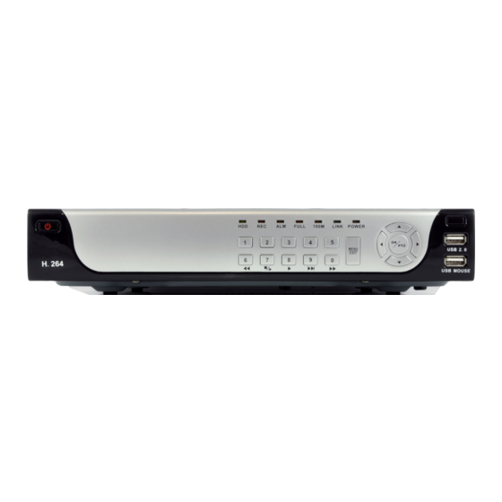
4. DVR INSTALLATION GUIDELINES 4.1 PRODUCT OVERVIEW 1. DEFINITION OF THE BUTTONS AND CONNECTORS ON THE FRONT PANEL Buttons on Front Panel Item Type Name Instruction Standby STANDBY System standby button Direction keys include: up【 】、down【 】、left 【 】、 Direction key right 【... - Page 37 2. THE DEFINITION OF BUTTONS AND CONNECTORS ON THE REAR PANEL The example below shows an 8 Channel System, but the connections for a 4 Channel System are exactly the same except there are fewer Video Inputs and Alarm Inputs. Connectors on Rear Panel Item Physical Connector...
- Page 38 3. SYSTEM NETWORK DIAGRAM The example below shows an 8 Channel System, but the connections for a 4 Channel System work in the same way.
-
Page 39: Hdd Installation
4.2 HDD INSTALLATION Caution: When working with electrostatic sensitive devices such as Hard Disks or the DVR unit, make sure you use a static-free workstation. Any electrostatic charge coming into contact with the Hard Disk or DVR can damage it permanently. Please install the HDD using the following steps: 1)Open the cover of the DVR and then you will see one HDD plate as follow. -
Page 40: Frequently Asked Questions
5. Frequently Asked Questions If your problem is not listed below, please call our support line on 09015565758 (calls charged at 50p per minute) or email support@cnmsecure.com. Question: DVR is not working after starting? Answer: Check the adaptor input. Check the power line, is it well-connected? Check the power on-off. - Page 41 Question: DVR cannot record after startup and the interface is showing "H" Answer: Make sure power adaptor is DC 19V. Make sure HDD is formatted. Check the power and data connection cables of the HDD. The HDD is defective. The SATA port is not working. Question: What is meaning of“R”“M”“I”“H”...
- Page 42 Question: System time is not correct? Answer: Wrong setting or user did not click "Edit" to confirm. CMOS Battery is not connected properly. CMOS Battery is dead. Please change. 10. Question: Why the “Stop recording” using the right mouse button does not work, how to stop recording? Answer: The “Stop recording”...
- Page 43 14. Question: Cannot login via the Web Browser? Answer: Please check the network to see if it is connected. Check if LINK or 100M LED is displayed normally on the panel; use ping xxx.xxx.xxx.xxx (DVR IP) to check if the Internet is linked properly.
-
Page 44: Copyright
Loss of customer’s software, firmware, information, or memory data. Improper handling or installation. CnM Secure makes no other express warranty, whether written or oral, with respect to this product. Any implied warranty of merchantability or fitness for a particular purpose is limited to the one-year duration of this written warranty.
Need help?
Do you have a question about the 8 Channel H.264 Digital Video Recorder and is the answer not in the manual?
Questions and answers