Table of Contents
Advertisement
Quick Links
SERVICE MANUAL
8
2003
MA007
1
PRECAUTIONS . . . . . . . . . . . . . . . . . . . . . . . . . . . . . . . . . . . . . . . . . . . . . . . . . . . . . . . . . . . . . . . . . . . . . . . 1-3
2
SPECIFIC SERVICE INSTRUCTIONS . . . . . . . . . . . . . . . . . . . . . . . . . . . . . . . . . . . . . . . . . . . . . . . . . . . . . . 1-4
3
DISASSEMBLY . . . . . . . . . . . . . . . . . . . . . . . . . . . . . . . . . . . . . . . . . . . . . . . . . . . . . . . . . . . . . . . . . . . . . . . 1-5
4
ADJUSTMENT . . . . . . . . . . . . . . . . . . . . . . . . . . . . . . . . . . . . . . . . . . . . . . . . . . . . . . . . . . . . . . . . . . . . . . . 1-13
5
TROUBLE SHOOTING . . . . . . . . . . . . . . . . . . . . . . . . . . . . . . . . . . . . . . . . . . . . . . . . . . . . . . . . . . . . . . . . . 1-17
COPYRIGHT © 2003 VICTOR COMPANY OF JAPAN, LIMITED
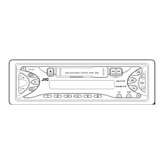
CASSETTE RECEIVER
KS-F171G
S.BASS
SEL
DISP
TABLE OF CONTENTS
Area Suffix
UN ------------- Asean
No.MA007
2003/8
Advertisement
Table of Contents

Related Manuals for JVC KS-F171G


Summary of Contents for JVC KS-F171G
-
Page 1: Table Of Contents
SERVICE MANUAL CASSETTE RECEIVER MA007 2003 KS-F171G S.BASS DISP Area Suffix UN ------------- Asean TABLE OF CONTENTS PRECAUTIONS ............... 1-3 SPECIFIC SERVICE INSTRUCTIONS . - Page 2 SPECIFICATION BAGIAN AMPLIFIER Output power maksimum Depan 45 watt per chanel AUDIO Belakang 45 watt per chanel 17 watt per chanel dalam 4 Ω, 40 Hz hingga 20 Output Power kontinyu Depan (RMS) 000 Hz dengan tidak lebih dari 0.8% distorsi harmonis total.
-
Page 3: Precautions
SECTION 1 PRECAUTION Safety Precautions Burrs formed during molding may be left over on some parts of the chassis. Therefore, pay attention to such burrs in the case of preforming repair of this system. (No.MA007)1-3... -
Page 4: Specific Service Instructions
SECTION 2 SPECIFIC SERVICE INSTRUCTIONS This service manual does not describe SPECIFIC SERVICE INSTRUCTIONS. 1-4 (No.MA007) -
Page 5: Disassembly
SECTION 3 DISASSEMBLY Main body 3.1.1 Removing the front panel assembly (See Fig.1) (1) Press the release button and remove the front panel as- sembly. Front panel assembly Release button Fig.1 3.1.2 Removing the bottom cover (See Fig.2) • Prior to performing the following procedure, remove the front panel assembly. - Page 6 3.1.4 Removing the heat sink (See Fig.4) • Prior to performing the following procedure, remove the front panel assembly. (1) Remove the screw B and two screws C attaching the heat sink on the left side of the body, and remove the heat sink. Heat sink Fig.4 3.1.5 Removing the rear panel...
- Page 7 3.1.7 Removing the cassette mechanism assembly (See Fig.7) • Prior to performing the following procedure, remove the front panel assembly, bottom cover, front chassis, heat sink, rear Cassette mechanism assembly panel and main board. (1) Remove the four screws H attaching the cassette mecha- nism assembly from the top chassis.
- Page 8 3.1.10 Removing the mecha bracket (See Fig.10) • Prior to performing the following procedure, remove the front panel assembly, bottom cover, front chassis, heat sink, rear Mecha bracket panel, main board, cassette mechanism assembly, head am- plifier board and relay board. (1) Remove the four screws L attaching the mecha bracket.
- Page 9 Cassette mechanism assembly • Prior to performing the following procedures, remove the head 3.2.4 Removing the playback head amplifier board, the relay board and the mechanism bracket. (See Fig.2) • Prior to performing the following procedure, remove the direc- 3.2.1 Removing the direction switch board tion switch board and the FF / REW lever assembly.
- Page 10 3.2.6 Removing the cassette hanger / cassette holder Cassette holder Return link (See Fig.3) Joint i • Prior to performing the following procedure, remove the FF / Cassette hanger REW lever assembly. Eject lever (1) From the rear of the unit, bend the two tabs f outwards and disengage the two joints g in the direction of the arrow.
- Page 11 3.2.9 Removing the Flywheel (BF) and (BR) assembly 3.2.10 Removing the reel base assembly (See Fig.4 and 5) (See Fig.5 and 6) • Prior to performing the following procedure, remove the cas- (1) Raise the part k of the reel base assembly slightly and re- sette hanger / cassette holder.
- Page 12 3.2.11 Removing the mute switch board (See Fig.8) Cassette mechanism assembly Rower switch (1) Unsolder the two wires l on the mute switch board on the back of the cassette mechanism assembly. Soldering l Motor assembly (2) Remove the screw H attaching the mute switch board. switch board Mute Fig.8...
-
Page 13: Adjustment
SECTION 4 ADJUSTMENT Adjustment method Test instruments required for adjustment Standard volume position (1) Digital oscilloscope (100MHz) Balance and Bass, Treble volume, Fader : Center (Indication "0") (2) Frequency counter meter Loudness, Dolby NR, Sound, Cruise : Off (3) Electric voltmeter Volume position is about 2V at speaker output with following (4) Wow &... - Page 14 Information for using a car audio service jig (1) We're advancing efforts to make our extension cords common for all car audio products. Please use this type of extension cord as follows. (2) As a U-shape type top cover is employed, this type of extension cord is needed to check operation of the mechanism assembly after disassembly.
- Page 15 Arrangement of adjusting & test points Cassette mechanism (Surface) Motor assembly Tape speed adjust Playback head Azimuth screw Head section view Head azimuth screw Fixed screw Playback head Height adjusting screw a Height adjusting screw c Height adjusting screw b (No.MA007)1-15...
- Page 16 Item Conditions Adjustment and Confirmation methods S.Values Adjust 1. Head azi- Test tape: Head height adjustment muth adjust- SCC-1659 Adjust the azimuth directly. When you adjust the height A line ment VT703 (10kHz) using a mirror tape, remove the cassette housing from the mechanism chassis.
-
Page 17: Trouble Shooting
SECTION 5 TROUBLE SHOOTING This service manual does not describe TROUBLE SHOOTING. (No.MA007)1-17... - Page 18 VICTOR COMPANY OF JAPAN, LIMITED AV & MULTIMEDIA COMPANY MOBILE ENTERTAINMENT CATEGORY 10-1,1chome,Ohwatari-machi,Maebashi-city,371-8543,Japan (No.MA007) Printed in Japan...
-
Page 19: Schematic Diagrams
SCHEMATIC DIAGRAMS RADIO KASET KS-F171G CD-ROM No.SML200309 Area Suffix UN ----------------------------Asean S.BASS DISP Contents Block diagram Standard schematic diagrams Printed circuit boards 2-5,6 No.MA007SCH COPYRIGHT 2003 VICTOR COMPANY OF JAPAN, LTD. 2003/9... -
Page 20: Safety Precaution
Safety precaution Burrs formed during molding may be left over on some parts of the chassis. Therefore, pay attention to such burrs in the case of preforming repair of this system. -
Page 21: Block Diagram
Block diagram Mechanism control board Relay board MAIN MOTOR HEAD MUTE SW CP721 TAPE/RADIO SW PROG.SW. SPEAKER CONNECTOR LINE REAR OUT CN721 CP981 CJ921 CJ901 LFO+,LFO- LRO+,LRO- RFO+,RFO- RRO+,RRO- IC981 POWER AMP IC901 HEAD AMP TAPE L IC931 E.VOL Head amplifier section LCD1 S3 to S47 TAPEIN... -
Page 22: Standard Schematic Diagrams
Standard schematic diagrams Main amplifier section QAU0281-001 Q989 KRA102M-T QNZ0009-001 ACC.MUTE Q972 KRA102M-T 1SS119-041 D973 MUTE2 CJ921 QNN0519-001 R163 4.7u R164 R165 D161 1SS119-041 2.2K D261 R265 MUTE 1SS119-041 2.2K R263 R264 R774 1.5K KTA1267/YG/-T 2SA1706/ST/-T C772 R773 2.2/50 R772 C773 C786 220/10... - Page 23 LCD & Key control section VMC0335-001 CP701 D655 MA152WK-X COM1 R651 COM2 D654 1.5k MA152WK-X COM3 0.01 C651 LC75823W 4.7/6.3 C652 IC651 MA152WA-X D653 D652 R652 680p C653 MA152WA-X CLOCK DATA IC652 R601 R602 R603 R604 R605 RPM6938-SV4 1.2k R608 R610 R611 R607...
- Page 24 Head amplifier section CJ901 QGA2002C1-05 IC901 UPC1228HA C103 C203 R104 R204 330k 330k 100p 100p CP722 QGA2002F1-06 C901 CP721 QGB1214K1-06S CP901 QGB1214K1-06S...
- Page 25 Printed circuit boards Main board CP981 L981 C981 CJ921 D981 CP751 CN901 R787 C986 C983 C132 D771 C133 C940 C931 R771 C997 R721 C942 C996 R941 C933 R722 C934 R992 C250 C231 C941 R997 C994 R231 R991 C975 C232 Q161 Q971 C974 R232...
- Page 26 Front board Forward side D601 S621 S601 R611 D606 D616 R618 S604 D619 R617 S620 S603 S608 D605 D617 R603 R616 R602 S602 R615 S618 S605 D604 D620 D618 S619 LCD1 D608 S606 D615 D610 D614 S610 S609 S611 S612 S615 S616 S617...
- Page 27 < M E M O >...
- Page 28 VICTOR COMPANY OF JAPAN, LIMITED AV & MULTIMEDIA COMPANY MOBILE ENTERTAINMENT CATEGORY 10-1,1chome,Ohwatari-machi,Maebashi-city,371-8543,Japan Printed in Japan (No.MA007SCH)
-
Page 29: Parts List
PARTS LIST [ KS-F171G ] * All printed circuit boards and its assemblies are not available as service parts. Area suffix UN ----------------------------Asean - Contents - Exploded view of general assembly and parts list (Block No.M1) Cassette mechanism assembly and parts list (Block No.MP) Electrical parts list (Block No.01~03) - Page 30 Exploded view of general assmbly and parts list...
- Page 31 General Assembly Block No. [M][1][M][M] Symbol No. Part No. Part Name Description Local VKL7821-001 EJECT LEVER QYSPSPT2625Z SCREW 2.6mm x 2.5mm QYSDSP2604Z SCREW 2.6mm x 4mm(x4) QYSDST2605Z SCREW 2.6mm x 5mm(x2) GE20134-001A MECHA BKT GE10043-011A TOP CHASIS GE40135-001A EARTH PLATE GE30938-003A SIDE PANEL GE30393-001A...
- Page 32 Cassette mechanism assembly and parts list Block No. CDS-363SJ1...
- Page 33 Cassette mechanism Symbol No. Part No. Part Name Description Local Block No. [M][P][M][M] 1-0036-7089S 6P WIRE ASY(JVC Symbol No. Part No. Part Name Description Local 1-0036-7088S 5P WIRE ASY(JVC 2-1816-0032-E8S MYLAR WASHER(S) (x2) 2-1812-0030-D2S PSW-S (x3) X-0363-1001S MAIN CHASSIS AS...
- Page 34 Grease point 1/2 Grease FL-942 SW-902 SW-522B FG-84M CFD-409 Reverse side...
- Page 35 Grease point 2/2...
-
Page 36: Electrical Parts List
Electrical parts list Main board Symbol No. Part No. Part Name Description Local Block No. [0][1][0][0] C137 QFVD1HJ-154Z MF CAPACITOR 0.15uF 50V J Symbol No. Part No. Part Name Description Local C138 QCFB1HZ-104Y C CAPACITOR 0.1uF 50V Z C150 QERF1HM-225Z E CAPACITOR... - Page 37 Symbol No. Symbol No. Part No. Part Name Description Local Part No. Part Name Description Local QRE141J-752Y C RESISTOR 7.5kΩ 1/4W J X701 QAX0406-001Z CRYSTAL 4.500MHz R131 QRE141J-392Y C RESISTOR 3.9kΩ 1/4W J R132 QRE141J-752Y C RESISTOR 7.5kΩ 1/4W J R163 QRE141J-821Y C RESISTOR...
-
Page 38: Front Board
Symbol No. Part No. Part Name Description Local PL603 QLL0151-001 LAMP S601 NSW0124-001X TACT SW S602 NSW0124-001X TACT SW S603 NSW0124-001X TACT SW S604 NSW0124-001X TACT SW S605 NSW0124-001X TACT SW S606 NSW0124-001X TACT SW S608 NSW0124-001X TACT SW S609 NSW0124-001X TACT SW... - Page 39 <MEMO> 3-11...
- Page 40 Packing materials and accessories parts list Block No. KIT : A3 A4 A5 A6 3-12...
- Page 41 Packing and accessories Block No. [M][3][M][M] Symbol No. Part No. Part Name Description Local GET0178-001A INST BOOK GET0178-002A INSTALL MANUAL VKZ4027-202 PLUG NUT VKH4871-001SS MOUNT BOLT VKZ4328-001 LOCK NUT WNS5000Z WASHER GE40130-001A HOOK (x2) FSJB3002-30C HARD CASE GE20137-003A MOUNTING SLEEVE A 10 GE20135-006A TRIM PLATE...
Need help?
Do you have a question about the KS-F171G and is the answer not in the manual?
Questions and answers