Table of Contents
Advertisement
Advertisement
Table of Contents

Related Manuals for Risco Rokonet WisDom


Summary of Contents for Risco Rokonet WisDom
- Page 1 Installation and Programming Manual...
- Page 3 Installation and Programming Manual...
-
Page 4: Table Of Contents
Table of Contents Chapter 1: Introducing WisDom .....................1-1 What is the WisDom? ......................... 1-1 WisDom Architecture and Capabilities..................... 1-2 WisDom Features ..........................1-3 Technical Specifications........................1-4 Chapter 2: Mounting and Wiring the WisDom ...............2-1 WisDom Installation Steps......................... 2-1 WisDom Components ........................2-2 Mounting the WisDom........................ - Page 5 System: Service Information........................4-16 System: Version ............................. 4-16 Zones ..............................4-17 Zones: Allocation ............................ 4-17 Zones: Parameters ..........................4-18 One by One............................4-18 Zone Label ............................4-20 Zone Partition............................ 4-20 Zone Type............................4-21 Zone Sound ............................4-26 Zones: Testing............................4-28 Zones: Editing ............................4-29 Zones: Crossing .............................
- Page 6 Report Codes: Disarm ........................4-73 Report Codes: Wireless........................4-73 Report Codes: Miscellaneous......................4-74 Report Codes: Special Communication .....................4-75 Monitoring Station: Voice Alarm Verification..................4-76 Key-Fobs ............................4-77 Key-Fobs: Allocation ..........................4-77 Key-Fobs: Parameters ..........................4-78 Key-Fobs: Communication Test......................4-79 Keypads............................. 4-80 Keypads: Allocation ..........................4-80 Keypads: Communication Test .......................4-81 Exit Programming..........................
-
Page 7: Chapter 1: Introducing Wisdom
Chapter 1: Introducing WisDom This chapter provides a basic introduction to the WisDom system ,its architecture and capabilities, as described in the following sections: What is the WisDom? below WisDom Architecture and Capabilities, page 1-2 WisDom Features, page 1-3 Technical Specifications, page 1-3 What is the WisDom? The WisDom is a fully featured wireless security system, providing sophisticated solutions for alerting and reporting premises alarm signals. -
Page 8: Wisdom Architecture And Capabilities
WisDom Architecture and Capabilities The following diagram provides an overview of the WisDom's architecture and capabilities. Examine this figure before beginning your WisDom installation to obtain an overall picture of the full extent of the WisDom system's capabilities. Figure 1-1: WisDom Architecture and Capabilities WisDom Installation and Programming Manual... -
Page 9: Wisdom Features
WisDom Features The following illustration describes the main features of the WisDom. Figure 1-2: WisDom Features WisDom Installation and Programming Manual... -
Page 10: Technical Specifications
Technical Specifications The following technical specifications are applicable for the WisDom: Electrical Characteristics System Power 220\110VAC, External Transformer 1500mA, 9VAC Current Consumption 250 mA standby / 1200 mA maximum (Standby / Maximum) Backup Battery 6 x 1.5VDC Size AA, Alkaline 6 x 1.2V Size AA, rechargeable cells Relay Outputs 2 x 3 Amps 24 VDC programmable relay outputs... -
Page 11: Wisdom Installation Steps
Chapter 2: Installing the WisDom This chapter covers the installation procedures of the WisDom, as follows: WisDom Installation Steps, below WisDom Components, page, 2-2 Mounting the WisDom, page 2-3 Wiring the WisDom, page 2-6 WisDom Installation Steps The following workflow illustrates the recommended method for installing the WisDom. A detailed description of each step is provided in the following sections of this manual. -
Page 12: Wisdom Components
WisDom Components The illustration below shows the internal components when the front panel is separated from the back plate. Figure 2-1: WisDom Internal components Layout 1. Back panel 12. AC restore jumper (J6) 2. Tamper housing 13. Line seizure LED 3. -
Page 13: Mounting The Wisdom
Mounting the WisDom Choosing the mounting location Before you mount the WisDom, study the premises carefully in order to choose the exact location of the unit for the best possible coverage and yet easily accessible to prospective users of the alarm system. The mounting place of the WisDom should be: Try to centrally locate the system, as close as possible to the transmitters. - Page 14 3. Pull the WisDom battery housing outward (See figure 2-1) 4. Release the back panel holding tabs (see Figure 2-3) located on both sides of the PCB and pull out the PCB gently. Figure 2-3: Releasing the PCB 5. Hold the back panel against the wall as a template and mark the locations for the mounting holes (6 mounting holes are available).
- Page 15 10. Connect the desired wires to the back panel’s terminal block as illustrated in the WisDom Wiring Diagram on page 2-6. 11. If desired, before closing the unit: Set the jumpers as described on page 2-11. Set the LCD contrast as described on page 2-12. Return the battery housing (after placing the batteries) and attach the battery locking screw (if required).
-
Page 16: Wiring The Wisdom
Wiring the WisDom This step explains the various wiring and connection procedures that must be performed when wiring the WisDom, as follows IMPORTANT: Before wiring the WisDom, ensure that the connection to the power supplies, mains or battery, is switched OFF. Figure 2-6: WisDom Wiring Diagram Connecting AC Power The WisDom is powered by a safety approved 220/110VAC to 9VAC 1500 mA transformer... -
Page 17: Wiring The Bell Tamper
BELL Wiring the Bell Tamper Connect the bell tamper to the BELL TMP and COM terminals on the PCB’s block terminals using a 2.2 KΩ resistor. K EOL RESISTOR NOTE: Bell tamper will be indicated only if the system parameter External Bell, BELL TAMPER (quick key [1][2][31]) is defined as Yes. -
Page 18: Ground Connection
2. Adjust the sound to be produced (See Chapter 4 page 4-10, quick key [1][2][32]) depending on the type of sounder. For a loudspeaker without a built in siren driver, the WisDom produces a continuous or interrupted oscillating voltage. For a bell or electric siren the WisDom produces a steady 9VDC voltage or a slow pulsating voltage, depending on the alarm type. -
Page 19: Wiring The Hardwire Zone
Wiring the Hardwire Zone The WisDom supports 1 hardwire zone - Zone 33 which can be used for example to connect a key switch. Connect this zone using twisted–pair or 4-conductor cable wiring. The following diagram illustrates the various zone connections: NOTE: The hardwire zone cannot be used as a fire zone. -
Page 20: Auxiliary Terminal
Auxiliary Terminal Use the Auxiliary Power AUX (+) COM (-) terminals to power devices that require a 9VDC power supply with maximum current consumption of 200mA. IMPORTANT: During Main power failure the AUX output is deactivated to insure longer system backup time. NOTES: The total power from the AUX terminals should not exceed 200mA. -
Page 21: Jumpers Setting
Jumpers Setting The WisDom is equipped with internal jumpers. Use the following table to configure the jumpers according to the desired configuration: Jumpers on Position Function front panel Enables to default the panel and restore the WisDom to the manufacturers default settings. Position the jumper plug over both pins when reinstating factory installed defaults values to the Main Panel programming (refer to Chapter 3, Programming the WisDom) or for installing... -
Page 22: Adjusting The Lcd Contrast
Adjusting the LCD Contrast The WisDom includes a trimmer located on the PCB of the front panel, next to the default jumper (see figure 2-1) that enables you to adjust the brightness and contrast of the LCD display. It is recommended to adjust the LCD display after powering up the system but prior to reattaching the two sub-assemblies when closing the unit. -
Page 23: Chapter 3: Programming The Wisdom
Chapter 3: Programming the WisDom The WisDom is designed around microprocessor and EEPROM (Electrical Erasable Programming Read Only Memory), which stores the system’s operating program, as well as its programmable parameters, without dependency of external power sources. This chapter explains the WisDom programming options, how to use the keypad elements, and the basics about programming via the keys. -
Page 24: Using The Wisdom's Leds And Keys
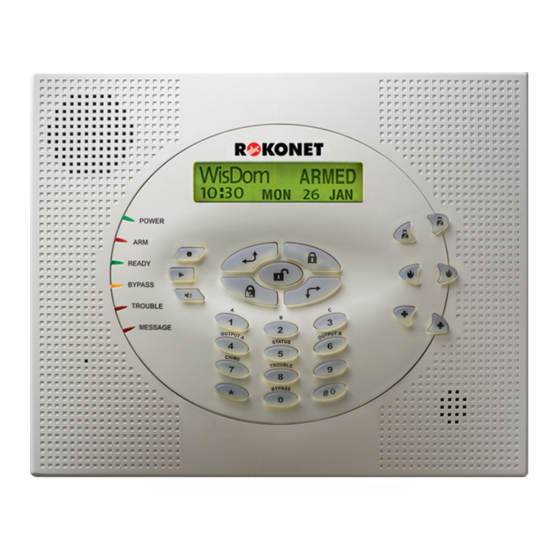
Using the WisDom’s LEDs and Keys Figure 3-1: The WisDom Surface The WisDom surface contains six LED indicators, an LCD display and a variety of keys. The LEDs have a different indication during programming mode than in normal operation mode. The LED’s indication in normal operation mode is described in the WisDom user manual. -
Page 25: Installer Programming From The Wisdom Keys
Item Key/LED Programming Mode LCD Program The LCD program display consists of two lines. The top line Display displays information about the main selection mode, and the bottom line displays information and/or data about the specific option set. Such data may be changed through keypad entry.When programming, up to 16-characters can be entered into a line, as required. - Page 26 operation mode will be: WisDom: WisDom: --:-- ..--:-- ..2. After pressing the keypad displays the first User Functions option, as follows: User functions: User functions: 1)Zone bypass 1)Zone bypass Press [9] to select the Installer option or use the key.
-
Page 27: Restoring Manufacturer's Defaults
Restoring Manufacturer's Programming Defaults You may find it useful to be able to remove all changes made to the WisDom’s programming and restore the default settings provided by the manufacturer. IMPORTANT: Before defaulting the WisDom you should enable the Default Enable/Disable parameter that controls the authority to restore to the manufacture’s defaults. -
Page 28: Keypad Timeout
Keypad Timeout If, after 15 minutes, during the installer programming, no entry is made to the keys the WisDom will produce an audible reminder, consisting of several beeps in rapid succession, along with the following display: TIMEOUT TIMEOUT HIT ANY KEY HIT ANY KEY Pressing any key stops the beeping. - Page 29 To load the Program Transfer module’s stored configuration into a WisDom: 1. Position the PTM on the J1 BUS connector located on the PCB of the back panel with the red LED not facing the row of terminals. The red LED flashes slowly. 2.
-
Page 30: Chapter 4: Using The Installer Programming Menus
Chapter 4: Using the Installer Programming Menus This chapter describes the WisDom’s installer programming options and functions, as well as all quick key shortcuts. They are presented in a table of menus are listed according to their number, as follows: System, page 4-2 Zones, page 4-17 Outputs, page 4-34... -
Page 31: System
To program the system using Quick Keys: 1. Access the Installer Programming menu and select the main menu option that you want to access (refer also to Chapter 3, Programming the WisDom). 2. Press the Quick Keys listed in sequence (from left to right) to locate the option listed in the Parameter column and then press NOTE: When programming items in sequence, you can use the... -
Page 32: System: Timers
System: Timers The Time Define menu contains parameters that specify the duration of an action. To access the Time Define menu: 1. Access the System menu, as described on page 4-2. 2. From the System menu, press [1] to access the Timers menu options. The following display appears: System timers: System timers:... -
Page 33: System: Control
System: Timers Quick Keys Parameter Default Range Confirm Time Window 30 minutes 30-60 minutes Specifies a time period that starts when an alarm is triggered for the first time. If a second alarm is triggered before the end of the confirmation time window, the WisDom will send a confirmed alarm to the Monitoring Station. - Page 34 System: Control Quick Keys Parameter Default Range False Code Trouble YES/NO YES: A False Code report is sent to the Central Station after three successive attempts at arming or disarming in which an incorrect User Code is entered. No alarm sounds at the premises, but a trouble indication appears on the system's keypad(s).
- Page 35 System: Control Quick Keys Parameter Default Range Fire Temporal Pattern YES/NO YES: During a fire alarm, the sounders produce a pattern of three short bursts, followed by a brief pause. NO: During a fire alarm, the flow of sounds produced by the sounder is a pattern of 2 seconds ON, then 2 seconds OFF.
- Page 36 System: Control Quick Keys Parameter Default Range Forced Keyswitch Arming YES/NO YES: Keyswitch arming is performed on any partition. Any violated (not READY) zone(s) in the partition will be bypassed automatically. The partition is then "force armed," and all intact zones are capable of producing an alarm. NO: The partition cannot be armed using a keyswitch until all violated (not READY) zones are secured.
- Page 37 System: Control Quick Keys Parameter Default Range Arm Pre-Warning YES/NO Related to auto arm/disarm operation. YES: For any partition(s) set up for Auto Arming, an audible Exit Delay (warning) countdown will commence 4.25 minutes prior to the automatic arming. (Refer to the user's Daily Arm function in the WisDom User's Manual for additional details.) During this period, Exit Delay beeps will be heard.
- Page 38 System: Control Quick Keys Parameter Default Range IMQ Install YES/NO YES: Causes the following parameters to function as follows: Auto Arm Bypass: If there is an open zone during the Auto Arm process, the system will be armed, and a silent alarm will be activated (unless the open zone is closed).
- Page 39 System: Control Quick Keys Parameter Default Range Area YES/NO Changes the system operation to Area instead of Partition, which then changes only the operation of the common zone. YES: When selected, the following points are relevant: The common zone will be armed after any partition is armed. The common zone will be disarmed only when all partitions are disarmed.
-
Page 40: System: Receiver
Receiver The Receiver menu contains parameters that control the WisDom receiver. To access the Receiver menu: 1. Access the System menu, as described on page 4-2. 2. From the System menu, press [3] to access the Receiver menu options. The following display appears: Receiver: Receiver:... -
Page 41: System: Clock
System: Receiver Quick Keys Parameter Default Range Jamming Time No Jamming NONE, 10, 20 or detection 30 seconds Specifies the period of time that the WisDom's receiver tolerates unwanted radio frequencies capable of blocking (jamming) signals produced by the system's transmitters. Once the specified time is reached, the WisDom sends a Report Code to the Central Station. -
Page 42: System: Labels
System: Labels The System Labels menu enables you to modify the labels displayed by the LCD that identify the system and partition labels. Entering a New Label Using the WisDom Keys You can rename the labels that identify zones and partitions by changing the default labels (Partition 1, Partition 2, and so on) to, for example, The Jones's, Sales Dept, or Mastr Bedr as appropriate. - Page 43 To access the System Labels menu: 1. Access the System menu, as described on page 4-2. 2. From the System menu, press [5] to access the Labels menu options. The following display appears: Labels: Labels: 1)System 1)System 3. Access and configure the parameters in the System Labels menu, as follows: System: Labels Quick Keys Parameter...
-
Page 44: System: Tamper Sound
System: Tamper Sound The Tamper Sound menu contains parameters that enable you to set the sound(s) that will be produced by the WisDom after a Tamper violation of a zone, the WisDom box, wireless keypad or any other device. To access the Tamper Sound menu: 1. -
Page 45: System: Service Information
3. Select the required option, as follows: ENABLE: The WisDom loses its programmed configuration, including all Labels and User/Installer Codes. It returns to its original, factory default configuration. Any user who knows the default User and Installer Codes can then reprogram it. DISABLE: An unauthorized user cannot return the system to the manufacturer’s default settings. -
Page 46: Zones
Zones The Zones menu provides access to submenus that are used for programming, defining, editing and testing each of the system's protected zones. After you access the Zones menu from the main Installer Programming menu, as described in this section, you can access the following submenus: Allocation, page 4-17 Parameters, page 4-18 Testing, page 4-28... -
Page 47: Zones: Parameters
Re (Write) Overwrite the data into the selected location and allocate the transmitter to a zone (within 255 seconds), according to the instructions supplied with each transmitter. If the WisDom successfully recognizes the transmitter it will sound a confirmation beep. Delete Erase the allocation data in the selected location and then press [Y] YES or [N] NO to confirm your choice... - Page 48 Zones: Parameters Quick Keys Parameter Default Range Zone Type: Select a type and press Zone Sound: Select a sounding method and press IMPORTANT: When using the One by One method, the listing of each zone's parameters is sequential. Once Zone 1's parameters have been programmed, they are followed by Zone 2's, then Zone 3's, and so forth.
-
Page 49: Zone Label
Zones: Parameters Quick Keys Parameter Default Range Zone Label The Zone Label menu enables you to create and/or edit up to 15 characters to describe each of the system's zones. Default: Zone 01, Zone 02, Zone 03, Zone 04 and so on for each zone Range: Any characters 1. -
Page 50: Zone Type
Zones: Parameters Quick Keys Parameter Default Range Zone Type The Zone Type menu contains parameters that enable you to program the zone type for any zone. Setting the zone type is partly determined by the arming levels, as follows: Disarm: The system reacts only to those zones defined as 24 HR, Fire, Panic, and Trouble. - Page 51 Zones: Parameters Quick Keys Parameter Default Range Exit (OP)/Entry Default for zone 1 ARM/STAY Used for an exit/entry door, open during the armed period. This zone behaves as described in the Exit/Entry 1 parameter, shown above, except that, if faulted when the system is being armed, it does NOT prevent arming.
- Page 52 Zones: Parameters Quick Keys Parameter Default Range I+Exit(OP)/Entry (Interior+Exit(OP)/Entry) Used for an exit/entry door that, for convenience, may be kept open when the system is being armed, as follows: In AWAY (ARMED) mode, refer to the explanation in Zone Type 03, page 4-22.
- Page 53 Zones: Parameters Quick Keys Parameter Default Range 24 Hours Usually assigned to protect non-movable glass, fixed skylights, and cabinets (possibly) for shock detection systems. A violation of such a zone causes an instant intrusion alarm, regardless of the system's state. Fire For smoke or other types of fire detectors.
- Page 54 Zones: Parameters Quick Keys Parameter Default Range Exit Termination This type of zone is used to avoid a false alarm by acting like an Exit (OP)/Entry zone (see Exit (OP)/Entry, see page 4-22). When triggered (after arming the system and closing the door or opening the door, arming the system, and closing the door), the system's Exit Delay time period will be shortened to 3 seconds.
-
Page 55: Zone Sound
Zones: Parameters Quick Keys Parameter Default Range Latch KSW Delay Used to apply the Exit/Entry Delay 1 parameter to the latched keyswitch operation. Zone Sound The Zone Sound menu contains parameters that enable you to program the sound produced when a system zone triggers an alarm. Reports to the Central Station are not affected by any of the options in this menu 1. - Page 56 Zones: Parameters Quick Keys Parameter Default Range (BELL/A BUZZER/D) In a case of alarm, the following occurs: In DISARM mode, only the buzzer will operate. In ARM mode, only the bell will operate. Force Arm This option enables or disables the use of forced arming for each of the system's zones, as follows: If forced arming is enabled for a particular zone, it allows the system to be armed even though this zone is faulted.
-
Page 57: Zones: Testing
Zones: Testing The Testing menu enables you to test the zones. To access the Testing menu: 1. Access the Zones menu, as described on page 4-17. 2. From the Zones menu, press [3] to access the Testing menu options. The following display appears Zone testing: Zone testing:... -
Page 58: Zones: Editing
1. From the Installer Programming menu, press quick keys [2] [3] [2]. The following display appears: Zones for test: Zones for test: 01)None 01)None 2. To put a zone on Soak Test, press . The following display appears: LOCATION 01: LOCATION 01: ZONE:00 ZONE:00... - Page 59 Zones: Editing Quick Keys Parameter Delete a Zone Deactivates a designated zone by setting its Zone Type to Not Used, while maintaining all the previously programmed parameters. 1. Press [2]. keys or the [1 to 9] keys to select the zone that 2.
-
Page 60: Zones: Crossing
Zones: Cross Zone Default: No cross zoning The Cross Zone menu is used for additional protection from false alarms and contains parameters that enable you to link together two related zones. Both must be violated within a designated time period (between 1 and 9 minutes) before an alarm occurs. This type of linking is used with motion detectors in hostile or false-alarm prone environments. -
Page 61: Zones: Alarm Confirmation
7. After choosing one of the above, press to define the maximum time-lapse interval between 1 and 9. The Time Slot parameter appears: Slot: Slot: 01,01: 01,01: Time=1 Minutes Time=1 Minutes 8. Enter the time slot, meaning the maximum amount of time allowed between the triggering events for them to be considered a valid violation (XX,YY indicate the crossed zones). - Page 62 Zones: Alarm Confirmation Quick Keys Parameter Default NOTES: 1. A confirmed zone will be part of the sequential confirmation only if the partition in which the alarm occurs is defined as confirmed partition as well. 2. Any Code can reset a confirmed alarm. 3.
-
Page 63: Outputs
Outputs The Outputs menu provides access to submenus and their related programming parameters that enable you to choose the event that will trigger a selected Utility Output, as well as the manner in which the output will be applied. In addition you can assign the outputs that will be activated by the user using the quick function key operation. - Page 64 Outputs: Define Quick Keys Parameter Follow Nothing The Nothing option enables you to disable the selected utility output Follow System The System menu contains Utility Output parameters that follow the System Event Bell Follow Activates when a bell is triggered. If a bell delay was defined, the Utility Output will be activated after the delay period.
- Page 65 Outputs: Define Quick Keys Parameter Follow Partition The Partition menu contains Utility Output parameters that follow the Partition Event. The Utility Output can follow any partition(s) combination Ready Follow Activates the Utility Output when all the selected partition(s) are in the READY state.
- Page 66 Outputs: Define Quick Keys Parameter Fire Trouble Follow Activates the Utility Output when a FIRE TROUBLE is detected in the selected partition(s). Day (Zone) Trouble Activates the Utility Output when a DAY ZONE TROUBLE is detected in the selected partition(s). General Trouble Follow Activates the Utility Output when a TROUBLE condition is detected in the selected partition.
- Page 67 Outputs: Define Quick Keys Parameter Zone Loss Alarm Activates the utility output when there is a lost wireless zone in the system and the IMQ bit is defined as YES (see page 4-9). The output restore shall be on Bell-Timeout or at user Disarm. Follow Zone The Zone menu contains Utility Output parameters that follow the Zone Event.
-
Page 68: Output Pattern Of Operation
Output Pattern of operation For each output you need to define the pattern of operation. Use the following table to select your option: Utility Output: Pattern of Operation Quick Keys Parameter Default Range Pulse N/C 05 seconds 01-90 seconds The Utility Output is always Activated (N/C) before it is triggered (pulled down to negative). -
Page 69: Activation/Deactivation
Utility Output: Pattern of Operation Quick Keys Parameter Default Range Pulse N/O 05 seconds 01-90 seconds The Utility Output is always Deactivated (N/O) before it is triggered (pulled up). When triggered, it activates (pulled down) for the Pulse Duration specified below, then deactivates automatically. -
Page 70: Output A
Outputs: Output A The Outputs: Output A menu defines which output will be activated, by the user, when using [4] from the WisDom keys. the key functions key To access the Output A menu: 1. Access the Outputs menu. 2. From the outputs menu press [2] to access the Output A menu. 3. -
Page 71: Code Maintenance
Code Maintenance The Code Maintenance menu provides access to submenus and their related parameters that enable you to maintain the User Codes in the system. In addition, the WisDom contains the following special codes: Grand Master Code: Used by the system's owner. Installer Code: Used by the WisDom installation company technician to program the system. -
Page 72: Code Maintenance: Authority
Code Maintenance: Authority Default: User The Authority menu enables you assign the Authority Level of each User Code. There are seven Authority Levels to match the needs of various users, as described in Authority Levels, below. To access the Authority menu: 1. -
Page 73: Code Maintenance: Partition
Changing his/her own User Code Controlling uploading/downloading activities Administering selected system tests, except Walk Testing Arm Only: There are no restrictions in the number of Arm Only Codes (as long as they don't exceed the number of codes remaining in the system). Arm Only Codes are useful for workers who arrive when the premises are already open, but because they are last to leave, they're given the responsibility to close the premises and arm the system. -
Page 74: Code Maintenance: Grand Master
Code Maintenance: Grand Master Default: 1234 The Grand Master menu enables the owner to set the Grand Master Code. NOTE: The Grand Master code can also be changed in the User menu (by the Grand Master). The Grand Master is the highest Authority Level. Refer to Authority Levels, page 4-43, for additional details about other authority levels. -
Page 75: Code Maintenance: Sub-Installer
Code Maintenance: Sub-Installer Default: 0233 The Sub-Installer Code allows limited access to selected parameters from the Installer Programming menu. The default Sub-Installer Code is: [0][2][3][3] We recommend changing the factory default to a code unique to the Main Panel and/or to those who may serve as sub-installers in your alarm company, as described in the following procedure. -
Page 76: Code Maintenance: Code Length
Code Maintenance: Code Length Default: 4 digits The Code Length specifies the number of digits (either 4 or 6) for the Grand Master, Manager, and Master Codes. All the other codes (User, Arm Only and Maid) use from one digit up to a maximum of six digits. To access and program the Code Length menu parameters: 1. -
Page 77: Dialer
Dialer The Dialer menu provides access to submenus and their related parameters that enable WisDom to establish communication with the Central Station and transmit data. After you access the Dialer menu from the main Installer Programming menu, as described in this section, you can access the following submenus: MS Telephone Numbers, page 4-48 MS Account Numbers, page 4-50... - Page 78 Dialer: MS Telephone Numbers Quick Keys Parameter Range MS Tel No. 1 Up to 32 alphanumeric characters The first Central Monitoring Station. 1. Press [1] and type in up to 32 digits. Include dialing prefixes and area code or special letters. When finished press If required, you can include the following special functions in the phone number to achieve the effect listed in the table.
-
Page 79: Dialer: Ms Account Numbers
Dialer: MS Account Numbers The Customer Account Numbers menu enables you to enter account numbers for each Central Station telephone number. These account numbers are the 6-digit Customer Account Numbers assigned by the Central Station. To access the MS Account Numbers menu: 1. - Page 80 5. Press 6. Press again followed by the key to return to the previous level. NOTE: For SIA and Contact ID formats, refer to Dialer: Auto Codes, page 4-66. 7. Access and configure the parameters in the Communication Format menu, as follows: Dialer: MS Communication Format Quick Keys Parameter...
-
Page 81: Dialer: Ud Telephone Number
Protocols Communication Formats Format Code Radionics Protocols: Radionics, 20 PPS handshake at 1400 Hz 0202 handshake at 2300 Hz 0212 Radionics, 20 PPS-Extended handshake at 1400 Hz 0242 handshake at 2300 Hz 0252 Radionics, 40 PPS handshake at 1400 Hz 0200 handshake at 2300 Hz 0210... - Page 82 Dialer: Access and ID Quick Keys Parameter Default Access Code 5678 Enables you to define an Access Code that is stored in the WisDom. Rokonet recommends using a different 4-digit Access Code for each installation. In order to enable communication between the Alarm Company and the WisDom, the same Access Code must subsequently be entered into the corresponding account profile created for the installation in the Upload/Download software.
-
Page 83: Dialer: Controls
Dialer: Access and ID Quick Keys Parameter Default MS Lock 000000 MS Lock is a security function used in conjunction with Rokonet's Upload/Download software. It provides greater proprietary security when viewing Central Station parameters. The same 6-digit code, which will be stored in the panel, must be entered into the corresponding account profile created for the installation in the Upload/Download software. - Page 84 Dialer: Controls Quick Keys Parameter Default MS Enable YES: Enables communication with the Central Station to report alarms, trouble, and supervisory events. NO: No communication with the Central Station is possible. Choose NO for installations that are NOT monitored by a Central Station. FM Enable YES: Enables Follow-Me communication.
- Page 85 Dialer: Controls Quick Keys Parameter Default Call Back U/D YES: Requires the WisDom system to call back the pre-programmed telephone number to which the alarm company's Upload/Download computer is connected. (Refer to Remote U/D Telephone No., page 4-52) This provides more security for U/D operations.
-
Page 86: Dialer: Parameters
Dialer: Controls Quick Keys Parameter Default Show Handshake YES: All LEDs on the WisDom light up for one second when the dialer receives the handshake signal from the Central Station's receiver. NO: Receipt of the handshake signal does not light up the LEDS Audible Kissoff YES: There is an audible sound emitted from the WisDom when the dialer receives the kissoff signal from the Central Station's receiver. - Page 87 Dialer: Parameters Quick Keys Parameter Default Range Rings to U/D 01 to 15 The number of rings before the WisDom answers an incoming call (for remote programming). NOTE: When the Answering Machine Override parameter is enabled (refer to page 4-56), this parameter is ignored.
- Page 88 Dialer: Parameters Quick Keys Parameter Default Range Pulse Duty Cycle 61/39% 67/33% and 61/39% For pulse dialing, choose the proper dialing duty cycle for the location, as described below. 67/33% Select [1] and press for European telephone systems. 61/39% Select [2] and press for USA telephone systems.
- Page 89 Dialer: Parameters Quick Keys Parameter Default Range Every other day Every 3rd day Every 4th day Every 5th day Every 6th day Once a week Press the key to return to the Dialer menu. UD Test HR:00 00-24 hours MIN:00 00-59 minutes Used to schedule periodic Auto Batch download using the Upload/Download software.
- Page 90 Dialer: Parameters Quick Keys Parameter Default Range Alarm Restore The Alarm Restore menu specifies under what conditions an Alarm Restoral is reported. This option informs the Central Station of a change in the specified condition(s) during an alarm restore. These reports need a valid Report Code. Refer to Report Codes, page 4-66, for additional details On BTO (Bell Time Out - Default) Reports the restoral after the audible alarm times out.
-
Page 91: Dialer: Report Split
Dialer: MS Report Split The MS Report Split menu contains parameters that enable the routing of specified events to up to three Central Station Receivers. To access the MS Report Split menu: 1. Access the Dialer menu, as described on page 4-48. 2. - Page 92 Dialer: Report Split Quick Keys Parameter Default Call 1st Reports urgent (alarm) events to the 1st telephone number. Call 2nd Reports urgent (alarm) events to the 2nd telephone number. Call 3rd Reports urgent (alarm) events to the 3rd telephone number. Call All Reports urgent (alarm) events to ALL telephone numbers.
-
Page 93: Dialer: Follow Me
Dialer: Follow-Me In addition to reporting to the Central Station, the WisDom has a Follow-Me feature, in which a standard phone call, reporting a system event, is made to a designated phone number. This procedure is useful to alert a homeowner at work, or a business owner at home, of an alarm. - Page 94 Dialer: Follow-Me Quick Keys Parameter Default [10] Disarm [11] Bypass [12] Wireless Lost N (When no supervision signal from the wireless zones is received.) [13] Wireless Low Batt N (Transmitters battery) [14] Bell Trouble [15] False Code N (When a wrong User Code is entered more than 3 times.) [16] Low Battery...
-
Page 95: Report Codes
Report Codes The Report Codes menu enables you to program the codes transmitted by the WisDom to report events (for example, alarms, troubles, restores, supervisory tests, and so on) to the Central Station, as follows: The codes specified for each type of event transmission are a function of the Central Station's own policies. - Page 96 Report Codes: Auto Codes Quick Keys Parameter Contact ID The WisDom allocates Report Codes supporting ADEMCO Contact (Point) ID. to select this option and deselect the SIA option (described 1. Press below). The following display appears: Point ID codes: Point ID codes: Auto allocate? N Auto allocate? N 2.
-
Page 97: Report Codes: Manual Codes
Report Codes: Manual Codes The Manual Codes menu enables to assign a specified report code for each event. Enter the 2-digit zone number and the corresponding 2-digit Report Code, representing the event in this zone. If this event is not to be transmitted, use the 00 default Emergency Key, page 4-68 Zones, page 4-69 Troubles, page 4-70... - Page 98 Report Codes: Manual Codes Quick Keys Parameter Duress To report a Duress Emergency (refer also to the WisDom's User's Manual). Restore Enter the 2-digit code used to report a restoral of the above keypad emergencies. Auxiliary Emergency (Special) To report the restoral of an Auxiliary Emergency. Panic To report the restoral of a Police Emergency.
- Page 99 Report Codes: Manual Codes Quick Keys Parameter Tamper To report a tamper for zone tamper alarm condition NOTE: If a zone with a tamper switch is bypassed, both the tamper switch and the Report Code are unaffected. Tamper Restore To report the restoral-to-normal of a tamper condition . Low Battery Trouble To report a low battery condition in a wireless transmitter.
- Page 100 Report Codes: Manual Codes Quick Keys Parameter False Code Code to report the repeated use of an incorrect User Code to disarm the system. Bell Tamper Code to report a tamper alarm of an external bell connected to the Main Panel. Box Tamper Code to report a tamper alarm of the tamper switch connected to the box.
- Page 101 Report Codes: Manual Codes Quick Keys Parameter The Arm Codes menu contains codes that enable the reporting of the Closing Signals generated when the system is ARMED (closed under a variety of conditions) User Arm 1. Enter the 2-digit Report Code representing the User. 2.
- Page 102 Report Codes: Manual Codes Quick Keys Parameter Disarm The Disarm Codes menu contains codes that enable the reporting of the Opening Signals generated when the system is DISARMED (opened) in various conditions) User Disarm Report Code used for system disarming (opening) by a particular user. Keyswitch Disarm Code to report system disarm via a keyswitch NOTE:...
- Page 103 Report Codes: Manual Codes Quick Keys Parameter Keypad Tamper Restore Code to restore to normal of a tamper condition Battery Trouble Report code for low battery condition in a wireless keypad Battery Trouble Restore Report code for correction of low battery condition Key Fobs Press [3] to access each sub-category, as shown in the following options Battery Trouble...
- Page 104 Report Codes: Manual Codes Quick Keys Parameter Cancel Report Report Code for a user-initiated cancellation of an alarm in progress. (Refer to the WisDom User's Manual for additional details.) Auto Arm Fail Report code for failing to perform automatic arming of the system. More More …...
-
Page 105: Monitoring Station: Voice Alarm Verification
Monitoring Station: Voice Alarm Verification The WisDom enables the Monitoring Station to perform Voice Alarm Verification in order to verify a cause of event or to guide someone in distress. NOTE: The receiver at the Monitoring Station should support this feature and be configured to enable the operator the option to perform the Listen-In and Talk functions. -
Page 106: Key-Fobs
Key-fobs The Key Fobs menu contains parameters that enable WisDom to allocate up to 8 rolling code Wireless key-fobs transmitters. The wireless key-fob transmitters (p/n RP128T4RC00A, RP296T4RC00A) are rolling code transmitters with the following options: Arm, Stay, Disarm, Panic, and UO activation. After you access the Key-fobs menu from the main Installer Programming menu, as described in this section, you can access the following submenu: Allocation, below... -
Page 107: Key-Fobs: Parameters
Key-fob: Parameters The Key fob Parameters menu defines the operation of the key fobs keys. Some of the keys may be used for arming and disarming the system and for various other operations. This procedure is required when using the 4-key wireless transmitter (rolling code). To access the Key –... -
Page 108: Key-Fobs: Communication Test
Fob:1 Butt:3 UO: Fob:1 Butt:3 UO: 01)Output 01 01)Output 01 8. After selecting the required option, press . The system moves to the next button, and the following display appears: Kef-fob:1 Kef-fob:1 Butt:4 Butt:4 1)None 1)None 9. Set the parameters for the button #4 (the small button), from the following options: None: The button is disabled (default). -
Page 109: Keypads
Keypads The Keypads menu contains parameters that enable WisDom to allocate the data it receives from the wireless keypads. Up to 2 wireless keypad can be added to the system. The wireless keypads are rolling code transmitters with the following options: Arm, Stay, Disarm, Panic, and UO activation: After you access the Keypads menu from the main Installer Programming menu, as described in this section, you can access the following submenu:... -
Page 110: Keypads: Communication Test
Keypads: Communication Test The Keypads communication menu enables to perform a communication test between the wireless keypad and receiver. To access the Keypads Communication Test menu: 1. Access the Keypads menu, as described above. 2. From the Keypads menu, press [2] to access the Communication Test menu options. The following display appears: Keypad comm.test Keypad comm.test... -
Page 111: Exit Programming
Exit Programming The Exit Programming menu enables you to save any programming changes made during the current session. Important: Any changes you make to the programmed parameters are not saved until you exit the Installer Programming Menu correctly. NOTE: To exit the installer programming mode place the default jumper (J9) on 1 PIN To access the Exit Programming menu: 1. -
Page 112: Chapter 5: Installer Programming Within The User Programming Menu
Chapter 5: Installer Programming Within the User Programming Menu This chapter explains programming options that are located in the user’s programming menu, but can be performed either by the user or installer. Programming the voice messages, below Performing walk test, page 5-9 Programming the Voice Messages This section describes how to customize the spoken messages that the WisDom announces when you access the system from a remote telephone, or heard locally on the premises. -
Page 113: Voice Messages Types
Voice Messages Types Three types of spoken messages are heard in the WisDom: 1. Event announcement message: Upon event occurrence, the WisDom initiates a call to a remote Follow Me (FM) number, informing the user of a security situation by playing a pre-recorded Event announcement message. -
Page 114: Voice Message Labels
Voice Message Labels The Message Labels menu provides access to submenus that enable to Play, Record and Assign a pre-defined message for zones, partitions, utility outputs, macro keys and the common message. To select a message structure: 1. Access the Voice message menu. 2. - Page 115 Voice Message: Message Labels Quick Keys Parameter Default Range Zone Message 1. Press [2]. The following display appears: Zone#:01 Zone#:01 (01-33) (01-33) Zone 01 Zone 01 2. Select the zone number and press 3. Press the required option as follows: Press [1] to play the zone message.
- Page 116 Voice Message: Message Labels Quick Keys Parameter Default Range Partition Message 1. Press [3]. The following display appears: Choose Part.: Choose Part.: 1)Partition 1 1)Partition 1 2. Select the partition number. 3. Press the required option as follows: Press [1] to play the partition message. Press [2] to record a partition message.
- Page 117 Voice Message: Message Labels Quick Keys Parameter Default Range NOTE: The utility output must be defined as Follow Code in order for you to assign them to voice messages, see page 4-37, Follow User Code. To record a UO message: 1.
-
Page 118: Test Message
Test Message The Test Message menu enables to verify the operation of the WisDom’s voice capabilities locally or remotely (using a remote Follow-Me telephone number) To perform messages testing: 1. Access the Voice message menu. 2. Select [3] Test Message. The following display appears: Test message: Test message: 1)Send message... -
Page 119: Local Announcement Messages
Local Announcement Messages Upon event occurrence, the WisDom can announce the security situation to occupants of the premises by sounding a local Announcement message. This Announcement message can be enabled or disabled, per event. To Enable/Disable Announcement Message: 1. Access the Voice message menu. 2. -
Page 120: Walk Test
Walk Test The walk test enables the installer or the Grand Master to easily test and evaluate the operation of each zone in the system. NOTE: The difference between performing a walk test with an installer code compared to using the Grand master code relates to a tamper condition. -
Page 121: Appendix A: Report Codes
Appendix A: Report Codes This appendix provides descriptions of all the Report Codes sent to the Monitoring Station. Report Code Programming for SESCOA SUPERFAST (03B1) PROGRAMMED SESCOA CODE EVENT REPORTING EVENT ALPHA CODE DIGITS (RECOMMENDED) Identified Opening Identified Closing Opening (Not Identified) Closing (Not Identified) 24-Hour Report AC Fail... -
Page 122: Report Code Programming For Ademco Point (Contact) Id (0420
Report Code Programming for ADEMCO POINT (CONTACT) ID (0420) PROGRAMMED ADEMCO EVENT REPORTING EVENT (RECOMMENDED) DIGITS CODE Medical Key Fire Alarm Smoke Fire Key Panic Key Duress Silent Alarm Audible Alarm Burglary Perimeter Interior 24 Hour Entry/Exit Day/Night Outdoor Tamper General Alarm Sensor Tamper Accessory Tamper... - Page 123 PROGRAMMED ADEMCO EVENT REPORTING EVENT (RECOMMENDED) DIGITS CODE Arm/Disarm Out Of Window User Arm/Disarm (with User ID) User Arm/Disarm (Group No. + User ID) Auto Arm/Disarm Remote Arm/Disarm Quick Arm Keyswitch Arm/Disarm Callback Request False Security Code Zone Bypass Forced Arm Communication Test Exp.
- Page 124 PROGRAMMED SIA EVENT EVENT DIGITS CODE Forced Closing Close Area ('System has been partly armed') Late Close Early Close Closing Report Automatic Closing ('+ User Number') Closing Keyswitch Point Closing Dummy Access Denied – Unknown Code Access Trouble Expansion Device Restoral Expansion Device Trouble Fire Alarm Fire Bypass...
- Page 125 PROGRAMMED SIA EVENT EVENT DIGITS CODE Cancel Report Open Area ('+ Area Number') Dummy Late Open Early Open Opening Report Disarm from Alarm Opening Keyswitch Point Opening ('+ Zone or Point') Panic Alarm Panic Alarm Restore Panic Trouble Restore Panic Trouble Emergency Alarm Emergency Alarm Restore Emergency Trouble Restore...
- Page 126 PROGRAMMED SIA EVENT EVENT DIGITS CODE RF Interface Transmitter Battery Restoral RF Receiver Tamper Transmitter Battery Trouble Bell Fault Receiver/Transmitter Communication Fail Bell Restoral Communication Restoral System (Transmitter/Receiver) Battery Missing Power Supply Trouble (Transmitter/Receiver) Power Supply Restored (Transmitter/Receiver) System Battery Restoral Communication Trouble (Transmitter/Receiver) System Battery Trouble Dummy...
-
Page 127: Appendix B: Event Log Messages
Appendix B: Event Log Messages This appendix provides descriptions of all the Event Log messages. EVENT MESSAGE DESCRIPTION Activate UO=X UO XX activation Actv UO=XX WB=YY UO XX is activated from key-fob YY Alarm Z=XXX Alarm in zone No. XXX Alarm abort P=X Alarm aborted on Partition X Arm:P=X WB=YY... - Page 128 EVENT MESSAGE DESCRIPTION Found Z=XXX Wireless zone found, zone No. XXX Func=XX C=YY Quick key function XX by user YY Home:P=X C=YY Partition X is armed in Stay(Home) mode by user YY Home:P=X WB=YY Partition X is armed in Stay(Home) from key-fob YY Jamming restore Wireless jamming restore Ksw arm:P=X...
- Page 129 EVENT MESSAGE DESCRIPTION Tamper KP=XX Tamper alarm from keypad ID=XX (The WisDom is recognized as KP=03) Tamper UO=X Tamper alarm from X10 expander ID=X Tamper Z=XXX Tamper alarm from zone No. XXX Tamper rst KP=XX Keypad XX tamper restore Tamper rst UO=X Tamper alarm restore from X10 expander ID=X Tamper rs Z=XXX Tamper alarm restore on zone No.
-
Page 130: Appendix C: Wisdom Accessories
Appendix C: WisDom Accessories Wireless Transmitters Description 868 MHz RWT92086800A Wireless PIR detector 868 MHz RWT92P86800A Wireless PIR detector with pet immunity 868 MHz RWT32S86800A Wireless smoke detector 868 MHz RWT72C86800A Wireless door contact transmitter 868 MHz RWT72M86800A Wireless door contact + magnet transmitter 868 MHz RWT72P86800A Door / Shutter Wireless contact 868 MHz RWT72X86800A... - Page 131 NOTES...
- Page 132 RTTE Declaration Of Conformity Hereby, Rokonet Electronics Ltd, declares that these control panels (RWSAL0868xxA*, RWSALV868xxA*, RWSAL0433xxA*, RWSALV433xxA*), with wired accessories (including cables) and wireless accessories, is in compliance with the essential requirements and other relevant provisions of Directive 1999/5/EC The RWSAL0868xxA*, RWSALV868xxA* are restricted for use in the Slovak Republic. The RWSAL0433xxA*, RWSALV433xxA* are not restricted for use in any of the European Community Countries *: xx represents a country or customer code.
- Page 133 Contacting Rokonet Rokonet Electronics Ltd. is committed to customer service and product support. You can contact us through our website (www.rokonet.com) or at the following telephone and fax numbers: Brazil Tel: +55 (11) 3661-8767 Fax: +55 (11) 3661-7783 Israel Tel: +972 (3) 9637777 Fax: +972 (3) 9616584 Italy Tel: +39 (02) 392-5354...
Need help?
Do you have a question about the Rokonet WisDom and is the answer not in the manual?
Questions and answers