Table of Contents
Advertisement
Advertisement
Table of Contents

Related Manuals for Risco WiComm


Summary of Contents for Risco WiComm
- Page 1 WICOMM Reference Manual...
-
Page 2: Table Of Contents
NSTALLATION SYSTEM COMPONENTS ............5 ................5 NCLUDED IN THE ................... 6 PTIONAL EVICES ....................8 ERIAL UMBERS GUIDELINES FOR USING THE RISCO EXPRESS INSTALLATION WIZARD ............10 ..................10 NSTALLATION ..................10 ELCOME CREEN ....................10 ERSONAL ....................10 YSTEM ..................... - Page 3 WIRELESS DEVICE ALLOCATION ........28 ................. 29 ABLE OF DDITIONAL EVICES LOGGING INTO THE USER WEB & APP ....... 30 .................. 31 ETTING THE .................. 31 HANGING ODES ..................33 HANGE ABELS STANDARD LIMITED PRODUCT WARRANTY..... 34 WiComm Reference Manual...
-
Page 4: Introduction
Note: It is recommended to add additional devices before starting the self- installation process. Self-Installation For basic and simple installation it is necessary to use the RISCO Express Wizard that explains step-by-step on how to program and install the system (see 3. GUIDELINES FOR USING THE RISCO EXPRESS WIZARD). -
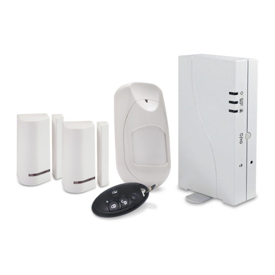
Page 5: System Components
Contains FCC ID:QIPEHS6 Frequency:915Mhz ,916Mhz Keychain remote Model:WL 132KF1 FCC ID: JE4WL132KF1915 Frequency:915Mhz Two Magnetic Door/Window Contacts (include sensor and magnet) Models: RWX73F FCC ID: JE4RWX73F915 Frequency:915Mhz A “pet-friendly” PIR Motion Sensor Models: RWX95P FCC ID: JE4RWX73F915 Frequency:915Mhz WiComm Reference Manual... -
Page 6: Optional Devices
Wireless Slim Keypad including proximity reader for using proximity tags Models: RW132KL1P, RW132KL2P FCC ID: JE4RW132KLXP1356 Contains FCC ID: JE4STAMP915 Frequency:915Mhz,13.56Mhz LCD Keypad including proximity reader for using proximity tags Model: RW132KPPW3 FCC ID: JE4RW132KPP1356 Contains FCC ID: JE4STAMP915 Frequency:915Mhz,13.56Mhz WiComm Reference Manual... - Page 7 Model:WL S42 Contains FCC ID: JE4STAMP915 Frequency:915Mhz Wireless acoustic Glassbreak Detector Model: RWT6G FCC ID: JE4RWT6G915 Frequency:915Mhz Wireless Flood Detector and Sensor Model: RWT6F FCC ID: JE4RWT6F915 Frequency:915Mhz NOTE: For device Technical Specifications, see RISCO’s website at https://www.riscogroup.com. WiComm Reference Manual...
-
Page 8: Serial Numbers
Serial Numbers Serial numbers are used to identify the components of your security system as used in the RISCO Express Wizard. Each serial number consists of 11 digits. Keep a record of components serial numbers and location by entering the relevant information in the table below that correspond to the devices serial numbers, as shown in these illustrations. - Page 9 Component Serial number (S/N) Installation location / zone description WiComm Reference Manual...
-
Page 10: Guidelines For Using The Risco Express Installation Wizard
Guidelines for using the RISCO Express Installation Wizard Self-Installation It is necessary to use the RISCO Express Wizard to successfully and professionally install your WiComm Smart Hub System. The RISCO Express Wizard walks you through the programming and installation of the system and connecting to the Cloud and Monitoring Station. -
Page 11: Set-Up Devices
Connect to Network Connecting a network cable to the WiComm Your WiComm communicates via 3G cellular and/or internet. For 3G cellular you need to install a SIM card with data communication enabled (check with your SIM card provider). For internet communication, connect the incoming network cable to the plug-in. -
Page 12: Done
SIM and enable it to operate. Locking Switch Important: Do not install SIM card while power is applied to the WiComm. Connecting the WiComm to Power Supply Plug in the power adapter to your security system. Verify the following: ... -
Page 13: Control Panel Indications And Connections
Color State Status Green Power OK AC trouble Power LED Orange Battery trouble. System armed (Away or Stay) rapid flash Alarm System is in entry/exit delay slow flash before disarming/arming the Status LED system Green System ready WiComm Reference Manual... -
Page 14: Control Panel Rear View
GSM/IP connecting Communication Orange slow flash GSM/IP error Battery Replacement mode Orange Slow flash (service mode) All LEDs Sequence Green Wireless Learn mode flash Control Panel Rear View Ethernet connection Power Adaptor connector SIM Card slot. WiComm Reference Manual... -
Page 15: Device Mounting Considerations
Min. 3 ft (1m) Min. 3 ft (1m) Min. 3 ft (1m) Min. 3 ft (1m) Min. 3 ft (1m) NOTE: The above illustrative diagram is intended to provide best results. WiComm Reference Manual... -
Page 16: Wireless Signal Loss Through Certain Building Materials
Heavy Concrete and Steel Reinforcement Placing the main Unit For upright independent placement: Stand the control panel on a surface (e.g. table), adjust the swivel base of the control panel so that it is a stable upright positioning. WiComm Reference Manual... -
Page 17: Mounting Considerations For Magnetic Contacts
Mounting considerations for magnetic contacts Wood & Metal Frame Wood Frame Max. 0.4 in (1cm) Metal Frame (possible 30% signal loss) For metal frame - wood or plastic spacer is required Max. 0.2 in (0.5cm) WiComm Reference Manual... -
Page 18: Mounting Considerations For Pir Detectors
NOTE: Place the sensor just a foot (30 cm) or so lower than the ceiling. To provide maximum coverage, the sensor should be placed in a corner facing away from any windows and ideally towards the entrance of the room, or, follow the height specified in their Installation Instructions WiComm Reference Manual... -
Page 19: Activating The Battery Of Door / Window Sensor
How to Mount the Door / Window Sensor Mounting with Adhesive Tape Peel the two-sided adhesive tapes from the sensor and magnet and attach the sensor and magnet to the mounting location. Adhesive tapes Door / Window Sensor Magnet WiComm Reference Manual... - Page 20 (A). At the mounting location, note the alignment marks for both components (B), and then install accordingly using 2 mounting screws (C). Detach magnet casing (D) and install with mounting screws (E). Back side of Bracket transmitter WiComm Reference Manual...
- Page 21 The mark on the magnet’s case must be aligned with the mark on the transmitter’s case. Max. 0.4 in (1cm) WiComm Reference Manual...
-
Page 22: Battery Replacement Of Door / Window Sensor
Release screw using a Phillips screwdriver (A) and then insert a flathead screwdriver into the slot and twist to open cover (B). Insert the battery while observing + - polarity. Put back cover firmly into place and secure with screw. WiComm Reference Manual... -
Page 23: Activating The Batteries Of The Pir Detector
How to Mount the PIR Detector Mounting with Adhesive Tape Peel the two-sided adhesive tapes from the detector and attach the detector to the mounting location. Adhesive tape Use for corner mounting Use for surface mounting WiComm Reference Manual... - Page 24 Mounting with Screws Release screw using a Phillips screwdriver. Insert a flathead screwdriver into the slot and push to remove cover. WiComm Reference Manual...
- Page 25 Open the knockout holes of the mounting bracket, and use them as a template for mounting. Corner Mounting Surface Mounting WiComm Reference Manual...
- Page 26 Slide the PIR detector downward onto the mounting bracket. Insert and fasten the screw into the hole located at the bottom of the detector to lock the detector to the mounting bracket. WiComm Reference Manual...
-
Page 27: Battery Replacement Of Pir Detector
Battery Replacement of PIR Detector Press in the tab and lift to open the battery compartment cover. Insert the batteries while observing + - polarity. Slide back cover into place and secure with screw. WiComm Reference Manual... -
Page 28: Wireless Device Allocation
Wireless Device Allocation The initial installation of the system must be performed using the RISCO Express Wizard. If additional accessories are purchased at a later stage, they must be allocated (“enrolled”) to the system using the method described below, and not using the RISCO Express Wizard. -
Page 29: Table Of Additional Devices
Press the reset switch on the siren. After a Internal Sounder squawk sounds, you have 10 seconds to press on the tamper switch for at least 3 seconds. Press the tamper switch for 3 seconds. Glassbreak Detector WiComm Reference Manual... -
Page 30: Logging Into The User Web & App
Log into the iRISCO website at https://www.riscocloud.com. Enter your email address and password selected at the start of registration. For the required “PIN Code” enter your assigned 4-digit Master User code selected during the “User & Codes” stage of the RISCO Express Wizard. WiComm Reference Manual... -
Page 31: Setting The Time Zone
Click the Users link in the left-hand column of the screen. Select an existing user to edit. Select “+Add New User” to add a user that can control the system via the Web/APP and on a keypad, if installed. WiComm Reference Manual... - Page 32 Arm Only – used only to arm the system. Cleaner – used only for one-time arming and disarming. Duress – used to disarm the system when forced to, in which case it will send out a Duress notification. WiComm Reference Manual...
-
Page 33: Change Zone Labels
Change Zone Labels Click the Detectors link in the left-hand column of the screen. Select the detector you wish to edit. Select the pencil icon next to the zone label. Edit the zone label. Click Close. WiComm Reference Manual... -
Page 34: Standard Limited Product Warranty
RISCO, for a period of (i) 24 months from the date of connection to the RISCO Cloud (for cloud connected products) or (ii) 24 months from production (for other products which are non-cloud connected), as the case may be (each, the “Product Warranty Period”... - Page 35 Consequently RISCO shall have no liability for any personal injury, property damage or loss based on a claim that the product fails to give warning.
- Page 36 (2) This device must accept any interference received, including interference that may cause undesired operation. Changes or modifications to this equipment which are not expressly approved by the party responsible for compliance (RISCO Group's.) could void the user's authority to operate the equipment. FCC Note This equipment has been tested and found to comply with the limits for a Class B digital device, pursuant to part 15 of the FCC Rules.
Need help?
Do you have a question about the WiComm and is the answer not in the manual?
Questions and answers