Table of Contents
Advertisement
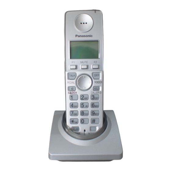
Telephone Equipment
KX-TG2873BXS
KX-TGA280BXS
Expandable Digital Cordless Answering
System
Silver Version
(for Asia, Middle Near East and Other areas )
© 2006 Panasonic Communications Co., Ltd. All
rights reserved. Unauthorized copying and distribu-
tion is a violation of law.
ORDER NO. KM40607135CE
Advertisement
Table of Contents
Troubleshooting

Related Manuals for Panasonic KX-TG2873BXS


Summary of Contents for Panasonic KX-TG2873BXS
- Page 1 ORDER NO. KM40607135CE Telephone Equipment KX-TG2873BXS KX-TGA280BXS Expandable Digital Cordless Answering System Silver Version (for Asia, Middle Near East and Other areas ) © 2006 Panasonic Communications Co., Ltd. All rights reserved. Unauthorized copying and distribu- tion is a violation of law.
- Page 2 KX-TG2873BXS/KX-TGA280BXS...
-
Page 3: Table Of Contents
KX-TG2873BXS/KX-TGA280BXS TABLE OF CONTENTS PAGE PAGE 1 Safety Precaution ------------------------------------------------ 4 13.7. Schematic Diagram (Charger Unit)------------------ 76 1.1. For Service Technicians --------------------------------- 4 13.8. For Signal Route ----------------------------------------- 77 2 Warning -------------------------------------------------------------- 4 14 Printed Circuit Board ------------------------------------------ 79 2.1. Battery Caution--------------------------------------------- 4 14.1. -
Page 4: Safety Precaution
KX-TG2873BXS/KX-TGA280BXS 1 Safety Precaution 1.1. For Service Technicians ICs and LSIs are vulnerable to static electricity. When repairing, the following precautions will help prevent recurring malfunctions. 1. Cover plastic parts boxes with aluminum foil. 2. Ground the soldering irons. 3. Use a conductive mat on worktable. -
Page 5: Suggested Pbf Solder
KX-TG2873BXS/KX-TGA280BXS 2.2.1. Suggested PbF Solder There are several types of PbF solder available commercially. While this product is manufactured using Tin, Silver, and Copper (Sn+Ag+Cu), you can also use Tin and Copper (Sn+Cu), or Tin, Zinc, and Bismuth (Sn+Zn+Bi). Please check the manufac- turer’s specific instructions for the melting points of their products and any precautions for using their product with other materi-... -
Page 6: Specifications
KX-TG2873BXS/KX-TGA280BXS 3 Specifications... -
Page 7: Technical Descriptions
KX-TG2873BXS/KX-TGA280BXS 4 Technical Descriptions 4.1. FHSS Description 4.1.1. Frequency The frequency range of 2.401 GHz - 2.482 GHz is used. Transmitting and receiving channel between Base Unit and Cordless Handset is same frequency. Refer to Frequency Table (P.66). 4.1.2. FHSS (Frequency Hopping Spread Spectrum) This telephone is using an IC chip which has similar specification to WDCT (World Digital Cordless Telephone) and is the tele- phone system that can use multiple portable unit simultaneously. -
Page 8: Block Diagram (Base Unit_Main)
KX-TG2873BXS/KX-TGA280BXS Block Diagram (Base Unit_Main) 4.2. -
Page 9: Circuit Operation (Base Unit_Main)
KX-TG2873BXS/KX-TGA280BXS Circuit Operation (Base Unit_Main) 4.3. General Description: DSP is a digital speech/signal processing system that implements all the functions of speech compression and memory management required in a digital telephone. The DSP system is fully controlled by a host processor DSP. The host processor provides activation and control of all that func- tions as follows. -
Page 10: Power Supply Circuit
KX-TG2873BXS/KX-TGA280BXS Power Supply Circuit 4.3.3. Function: The power supply voltage from AC adaptor is converted to the desired voltage of each block. Circuit Operation: Q304 and IC302: +5.5V DCDC Converter IC301 +5.0V Regulator IC601 +3.45V Regulator Q115 +3.0V IC4 I/O Voltage Q114 +1.8V IC4 Internal Voltage... -
Page 11: Reset Circuit
KX-TG2873BXS/KX-TGA280BXS Reset Circuit 4.3.4. Function: This circuit is used to initialize the microcomputer when it incorporates an AC adaptor. Circuit Operation: The system is reset when IC4’s BBIC internal voltage of BB1.8V goes down below 1.65V. -
Page 12: Telephone Line Interface
KX-TG2873BXS/KX-TGA280BXS Telephone Line Interface 4.3.5. Telephone Line Interface Circuit: Function • Ring signal detection • Clip signal detection • ON/OFF hook circuit • Pulse dial circuit • Side tone circuit Ring signal detection: In the standby mode, Q105 is open to cut the DC loop current and decrease the ring load. When ring voltage appears at the T (A) and R (B) leads (When the telephone rings), the AC ring voltage is transferred as follows: A →... - Page 13 KX-TG2873BXS/KX-TGA280BXS Transmitter/Receiver 4.3.6. Base unit and handset mainly consist of RF Module and BBIC. Base unit and handset transmit/receive voice signal and data signal through the antenna on carrier frequency.
-
Page 14: Block Diagram (Cordless Handset)
KX-TG2873BXS/KX-TGA280BXS Block Diagram (Cordless Handset) 4.4. LCD_Light Charge Charge Control Q500 D501 LED2,3,4 Q501 Q101 Q502 Battery Power Circuit IC300,IC301 Q300,Q301,Q302 EEPROM Receiver BBIC KEY_Light LED5,6,7,8,Q100 Speaker KEYS 10.368MHz RF_UNIT IC700 ANT_LED KX-TGA280 BLOCK DIAGRAM (Cordless handset) -
Page 15: Circuit Operation (Cordless Handset)
KX-TG2873BXS/KX-TGA280BXS Circuit Operation (Cordless Handset) 4.5. 4.5.1. Construction The circuit mainly consists of DSP and RF part as shown in the block diagram. 4.5.1.1. BBIC: IC1 Function: • Battery Low, Power down detect circuit • Ringer Generation • Interface circuit (RF part, Speaker, Mic, LED, Key scan, LCD) Initial waves: 4.5.1.2. - Page 16 KX-TG2873BXS/KX-TGA280BXS Power Supply Circuit 4.5.2. Circuit Operation: When power on the Cordless Handset, the voltage is as follows; BATTERY(2.2 V ~ 2.6 V: J1) → L502 → L300, D300 → Q300 (3.4 V) → Q302 (1.8 V), Q301 (2.5 V)
-
Page 17: Charge Circuit
KX-TG2873BXS/KX-TGA280BXS Charge Circuit 4.5.3. Circuit Operation: When charging the cordless handset on the Charger Unit, the charge current is as follows; AC Adaptor: DC+(6.5V) → [R1, R2, R3, R4 → CHARGE+ (Charger)] → CHARGE+ (Cordless Handset) → Q502 → D501 →... -
Page 18: Sending Signal
KX-TG2873BXS/KX-TGA280BXS Sending Signal 4.5.5. Battery Low/Power Down Detector 4.5.6. Circuit Operation: “Battery Low” and “Power Down” are detected by BBIC which check the voltage from battery. The detected voltage is as follows; • Battery Low Battery voltage: V (Batt) < 2.3V ± 50mV The BBIC detects this level and "... -
Page 19: Signal Route
KX-TG2873BXS/KX-TGA280BXS 4.7. Signal Route Each signal route is as follows. - Page 20 KX-TG2873BXS/KX-TGA280BXS Each signal route is as follows.
-
Page 21: Location Of Controls And Components
KX-TG2873BXS/KX-TGA280BXS 5 Location of Controls and Components 5.1. Controls 5.1.1. Base Unit 5.1.2. Charger Unit 5.1.3. Cordless Handset... -
Page 22: Display
KX-TG2873BXS/KX-TGA280BXS 5.2. Display 5.2.1. Base unit Display Items 5.2.2. Cordless Handset Display Items... -
Page 23: Installation Instructions
KX-TG2873BXS/KX-TGA280BXS 6 Installation Instructions 6.1. Connections... -
Page 24: Battery Installation/Replacement
KX-TG2873BXS/KX-TGA280BXS 6.2. Battery Installation/ 6.3. Battery Charge Replacement Note for service: The battery strength may not be indicated correctly if the battery is disconnected and connected again, even after it is fully charged. In that case, by recharging the battery as mentioned above, you will get a correct indication of the battery strength. - Page 25 KX-TG2873BXS/KX-TGA280BXS 6.3.2. Battery Performance...
-
Page 26: Operation Instructions
KX-TG2873BXS/KX-TGA280BXS 7 Operation Instructions 7.1. Guide to Cordless Handset Programming Note for service: When the display language is in Thai, press [F1][#][0][4][9][>] and [F1], then the display language will be changed into English. 7.1.1. Programming by Scrolling Through the Display Menus... - Page 27 KX-TG2873BXS/KX-TGA280BXS 7.1.2. Programming Using the Direct Commands...
-
Page 28: Dial Lock
KX-TG2873BXS/KX-TGA280BXS 7.2. Dial Lock This feature prohibits making outside calls. The default setting is OFF. Important: • When dial lock is turned on, you can dial the emergency calls in the following ways: - Phone numbers stored in the phonebook as emergency numbers (numbers stored with a # at the beginning of the name) can be dialed using the phonebook. -
Page 29: Error Messages
KX-TG2873BXS/KX-TGA280BXS 7.3. Error Messages... -
Page 30: Troubleshooting
KX-TG2873BXS/KX-TGA280BXS 7.4. Troubleshooting... - Page 31 KX-TG2873BXS/KX-TGA280BXS...
- Page 32 KX-TG2873BXS/KX-TGA280BXS...
- Page 33 KX-TG2873BXS/KX-TGA280BXS...
- Page 34 KX-TG2873BXS/KX-TGA280BXS...
-
Page 35: Test Mode
KX-TG2873BXS/KX-TGA280BXS 8 Test Mode 8.1. Test Mode Function (Base unit) -
Page 36: Test Mode Function (Cordless Handset)
KX-TG2873BXS/KX-TGA280BXS 8.2. Test Mode Function (Cordless Handset) Note: (*1) All key codes are shown in below table. -
Page 37: Service Mode
KX-TG2873BXS/KX-TGA280BXS 9 Service Mode 9.1. Copying Phonebook Items When Repairing... - Page 38 KX-TG2873BXS/KX-TGA280BXS Note: • If the max number of handsets are already registered to the base unit, a new handset cannot be registered. • To register the handset, refer to Re-registering the Cordless Handset (P.47) • To cancel the handset, refer to Canceling the Cordless Handset Registration (P.48)
-
Page 39: Service Mode Function (For Base Unit With Cordless Handset)
KX-TG2873BXS/KX-TGA280BXS 9.2. Service Mode Function (for Base Unit with Cordless Handset) Note for service: When the display language is in Thai, press [F1][#][0][4][9][>] and [F1], then the display language will be changed into English. 9.2.1. How to Clear User Setting... -
Page 40: Troubleshooting Guide
KX-TG2873BXS/KX-TGA280BXS 10 Troubleshooting Guide 10.1. Troubleshooting Flow Chart Cross Reference: Check Power (P.41) Check the Transmission (P.42) Check the Reception (P.42) Check Playback (P.43) Check Record (P.44) Check Battery Charge (P.45) Check Link (P.46) Check the RF part (P.47) Check Ring Reception (P.49) -
Page 41: Check Power
KX-TG2873BXS/KX-TGA280BXS 10.1.1. Check Power Cross Reference: Power Supply Circuit (P.10) Note: (*1) Refer to Specifications (P.6) for part number and supply voltage of AC adaptor. Flash Memory is IC601. DSP is IC501. - Page 42 KX-TG2873BXS/KX-TGA280BXS 10.1.2. Check the Transmission Cross Reference: Telephone Line Interface (P.12) Signal Route (P.19) 10.1.3. Check the Reception Cross Reference: Telephone Line Interface (P.12) Signal Route (P.19) Note: When checking the RF part, Refer to Check the RF part (P.47).
- Page 43 KX-TG2873BXS/KX-TGA280BXS 10.1.4. Check Playback Cross Reference: Power Supply Circuit (P.10) Signal Route (P.19) Note: Flash-ROM is IC501. BBIC(DSP) is IC4. SP-AMP is IC201.
- Page 44 KX-TG2873BXS/KX-TGA280BXS 10.1.5. Check Record 1. Press [F1] [#] [9] [0] [0] [0] [ ] key then it goes to “SERVICE MODE”. 2. Press [#] [5] [1] [0]. “VOX DETECT=06s” 3. Increase a set value within the range from 6 to 12s by inputting ten key.
-
Page 45: Check Battery Charge
KX-TG2873BXS/KX-TGA280BXS 10.1.6. Check Battery Charge Cross Reference: Telephone Line Interface (P.12) Signal Route (P.19) Note: (*1) Refer to Specifications (P.6) for part number and supply voltage of AC adaptor. Flash-ROM is IC501. BBIC(DSP) is IC4... -
Page 46: Check Link
KX-TG2873BXS/KX-TGA280BXS 10.1.7. Check Link Cross Reference: Power Supply Circuit (P.10) for Bade Unit Power Supply Circuit (P.16) for Cordless Handset Adjustment of Base Unit (P.62) Adjustment of Cordless Handset (P.63) -
Page 47: Check The Rf Part
KX-TG2873BXS/KX-TGA280BXS 10.1.8. Check the RF part 10.1.8.1. Finding out the Defective part After All the Checkings or Repairing 1. Re-register the checked CL-HS to the checked BU, and Standard CL-HS to Standard BU. Note: (*1) CL-HS: Cordless Handset (*2) BU: Base Unit... - Page 48 KX-TG2873BXS/KX-TGA280BXS 10.1.8.1.2. Canceling the Cordless Handset Registration 10.1.8.1.3. Copying Phonebook Items...
- Page 49 KX-TG2873BXS/KX-TGA280BXS 10.1.9. Check Ring Reception Cross Reference: Telephone Line Interface (P.12). 10.1.10. Check Caller ID Cross Reference: Telephone Line Interface (P.12). Note: • Make sure the format of the Caller ID Service of the Tele- phone company that the customer subscribes to.
-
Page 50: How To Replace The Flat Package Ic
KX-TG2873BXS/KX-TGA280BXS 10.2. How to Replace the Flat Package IC Even if you do not have the special tools (for example, a spot heater) to remove the Flat IC, with some solder (large amount), a soldering iron and a cutter knife, you can easily remove the ICs that have more than 100 pins. -
Page 51: How To Install The Ic
KX-TG2873BXS/KX-TGA280BXS 10.2.3. How to Install the IC 1. Temporarily fix the FLAT PACKAGE IC, soldering the two marked pins. *Check the accuracy of the IC setting with the corresponding soldering foil. 2. Apply flux to all pins of the FLAT PACKAGE IC. -
Page 52: Disassembly And Assembly Instructions
KX-TG2873BXS/KX-TGA280BXS 11 Disassembly and Assembly Instructions 11.1. Disassembly Instructions 11.1.1. Base Unit... - Page 53 KX-TG2873BXS/KX-TGA280BXS...
- Page 54 KX-TG2873BXS/KX-TGA280BXS...
- Page 55 KX-TG2873BXS/KX-TGA280BXS 11.1.2. Cordless Handset...
- Page 56 KX-TG2873BXS/KX-TGA280BXS 11.1.3. Charger Unit...
-
Page 57: Fix The Lcd And The Receiver Guide To The Main P.c.board (Cordless Handset)
KX-TG2873BXS/KX-TGA280BXS 11.2. Fix the LCD and the Receiver Guide to the Main P.C.Board (Cordless Handset) -
Page 58: Measurements And Adjustments
KX-TG2873BXS/KX-TGA280BXS 12 Measurements and Adjustments 12.1. Things to Do after Replacing IC Important: Please execute the adjustment process when you replace the following object parts. 12.1.1. Base Unit Necessary Adjustment BBIC CPU, interface for RF and FlashROM. 1. BandGAP adjustment (IC4) 2. -
Page 59: Equipment Required
KX-TG2873BXS/KX-TGA280BXS 12.2. The Setting Method of JIG (Base Unit) 12.2.1. Preparation 12.2.1.1. Equipment Required • Frequency counter: It must be precise enough to measure intervals of 1 Hz (precision; ±4 ppm). Hewlett Packard, 53131A is recommended. • Digital multi-meter (DMM): it must be able to measure voltage and current. -
Page 60: The Setting Method Of Jig (Cordless Handset)
KX-TG2873BXS/KX-TGA280BXS 12.3. The Setting Method of JIG (Cordless Handset) 12.3.1. Preparation 12.3.1.1. Equipment Required • Frequency counter: It must be precise enough to measure intervals of 1 Hz (precision; ±4 ppm). Hewlett Packard, 53131A is recommended. • DC power: it must be able to output at least 1 A current under 2.4 V for cordless handset. -
Page 61: Batch File Settings
KX-TG2873BXS/KX-TGA280BXS 12.4. Batch file Settings Note: • “****” varies depending on the country. 12.5. Commands See the table below for frequently used commands. Command name Function Example getver Check software version Type "getver", then registered software version is read out. -
Page 62: Adjustment Of Base Unit
KX-TG2873BXS/KX-TGA280BXS 12.6. Adjustment of Base Unit Cross Reference: Power Supply Circuit (P.10) -
Page 63: Adjustment Of Cordless Handset
KX-TG2873BXS/KX-TGA280BXS 12.7. Adjustment of Cordless Handset Cross Reference: Power Supply Circuit (P.16) -
Page 64: Base Unit Reference Drawing
KX-TG2873BXS/KX-TGA280BXS 12.8. Base Unit Reference Drawing When connecting the Simulator Equipments for checking, please refer to below. 12.8.1. Flow Solder Side View Note: (*1) is referred to The Setting Method of JIG (Base Unit) (P.59) (*2) is referred to Adjustment of Base Unit (P.62) -
Page 65: Cordless Handset Reference Drawing
KX-TG2873BXS/KX-TGA280BXS 12.9. Cordless Handset Reference Drawing When connecting the Simulator Equipments for checking, please refer to below. 12.9.1. Component View PFUP1609Z C415 D402 D403 ANT_2 C423 C424 ANT_1 C419 C418 TP700 C711 R713 Measurement Point (*2) R716 VDD5 VDD5 R106... -
Page 66: Frequency Table
KX-TG2873BXS/KX-TGA280BXS 12.10. Frequency Table Channel Center Frequency (MHz) RX Local Frequency (MHz) 66 (42H) 2458.08 2457.216 Channel Center Frequency (MHz) RX Local Frequency (MHz) 67 (43H) 2458.944 2458.08 2 (02H) 2402.784 2401.92 68 (44H) 2459.808 2458.944 3 (03H) 2403.648 2402.784 69 (45H) 2460.672... -
Page 67: Schematic Diagram
KX-TG2873BXS/KX-TGA280BXS 13 Schematic Diagram 13.1. For Schematic Diagram 13.1.1. Base Unit (Schematic Diagram (Base Unit_Main)) Notes: 1. DC voltage measurements are taken with an oscilloscope or a tester with a ground. 2. This schematic diagram may be modified at any time with the development of new technology. -
Page 68: Schematic Diagram (Base Unit_Main)
KX-TG2873BXS/KX-TGA280BXS 13.2. Schematic Diagram (Base Unit_Main) 150k R219 HSIN C120 K1000p C211 F13k R140 F5.6k R141 J15p C119 K330p C237 5.6k C209 R139 K1000p 100 R913 150k C123 R214 TP211 TP209 C117 K0.01u C204 220k R209 R138 C122 220k R254... - Page 69 KX-TG2873BXS/KX-TGA280BXS C603 K1000p K1000p C602 D10p C600 D10p C601 4.7k R424 2.2k 100k 220k R704 R423 560k R422 R207 R707 K0.015u C405 R415 100k R253 C411 C410 R421 R420 R417 R330 R418 C332 R416 R414 C408 C402 D316 C326 R411...
- Page 70 KX-TG2873BXS/KX-TGA280BXS R916 2.2k M4.7u C914 K330p C913 R504 C507 Z0.1u C502 C503 J15p K330p C228 AD[17] R255 R226 R227 R500 C508 J100p C506 K330p TP19 C131 K1000p TP16 100k K0.1u TP51 K0.01u 65 BE0n 66 SCL2/P3[0] AD23 67 SDA2 AD22...
- Page 71 KX-TG2873BXS/KX-TGA280BXS C230 J100p C53 J100p D603 C229 J100p C52 C919 D602 C918 C917 C916 K1000p C235 D203 J100p C231 D202 J100p C218 D201 K1000p C232 D200 C225 D204 ANSL Z0.1u K0.01u TOPL C222 SCL1 SDA1 AD[21] AD[19] AD[18] AD[17] AD[16] AD[15] Z0.1u...
-
Page 72: Schematic Diagram (Base Unit_Operation)
KX-TG2873BXS/KX-TGA280BXS 13.3. Schematic Diagram (Base Unit_Operation) +5.5V SW10 +VDD ROW0 SW17 SW18 SW19 SW22 ROW1 SW13 SW14 SW15 SW16 SW21 ROW2 LCD_TXD LCD_CLK SW11 SW27 LCD_START LCD_INH ROW3 SW12 SW20 ROW4 SW25 SW26 SW24 SW23 SW28 R105 ROW5 COL0 COL1... -
Page 73: Schematic Diagram (Base Unit_Mic)
KX-TG2873BXS/KX-TGA280BXS 13.4. Schematic Diagram (Base Unit_MIC) To Main PCB MIC+ TP10 1 HSMIC(+) 2 HSMIC(-) To Main PCB MIC- TP11 KX-TG2873 SCHEMATIC DIAGRAM (Base Unit_MIC) 13.5. Schematic Diagram (Base Unit_Back Light) +5.5VF BL_ON LED1 LED2 LED4 LED3 LED5 NC: No Components... -
Page 74: Schematic Diagram (Cordless Handset)
KX-TG2873BXS/KX-TGA280BXS 13.6. Schematic Diagram (Cordless Handset) Land for soldering VBAT VBAT L300 D300 L502 BATTERY+ For Battery terminal TX (cordless handset) L503 R301 RX (cordless handset) BATTERY- Q300 CHG+ Q502 D501 CHARGE+ For Charge terminal Q501 CHARGE- R500 Q500 CHG-... - Page 75 KX-TG2873BXS/KX-TGA280BXS +3.4V VDD5 +3.4V VBAT For Antenna IC300 Land for IC301 VOUT soldering VDDPA VOUT ANT_1 ANT_2 ON/OFF TP700 TXDA PAON 1 GND1 GND14 2 GND2 VCC_PA 3 GND3 GND13 R705 4 TXDATA PAON RSSI 5 RSSI IC700 PSEL 6 VCC_OC 6.8K...
-
Page 76: Schematic Diagram (Charger Unit)
KX-TG2873BXS/KX-TGA280BXS 13.7. Schematic Diagram (Charger Unit) -
Page 77: For Signal Route
KX-TG2873BXS/KX-TGA280BXS 13.8. Input Level (*1) RX (Handset), RX (SP-phone), and RX (Cordless Handset); • T-R (CN100: 3-4 pin) • TEST SIGNAL FREQUENCY: 1 kHz (with FEEDING Bridge circuit at IL = 80 mA) • The signal is input to between T-R, with the generator that set the output to -20 dBm. - Page 78 KX-TG2873BXS/KX-TGA280BXS Memo...
-
Page 79: Printed Circuit Board
KX-TG2873BXS/KX-TGA280BXS 14 Printed Circuit Board 14.1. Circuit Board (Base Unit_Main) 14.1.1. Component View R162 D108 C138 R171 D109 SW100 C128 R179 R126 C126 Q109 R908 C134 C143 Q112 R155 C135 D101 R175 Q122 R232 R177 Q119 C221 C923 C225 C222... -
Page 80: Flow Solder Side View
KX-TG2873BXS/KX-TGA280BXS 14.1.2. Flow Solder Side View C918 C917 TP43 C919 L203 L200 TP12 R129 Q900 R117 D203 R164 C151 D200 TP14 C235 C218 R180 C232 C231 Q901 TP11 C228 TP10 Q121 TP13 TP107 BB3.3V TP309 R102 (DG) R101 C903 C902... -
Page 81: Circuit Board (Base Unit_Back Light)
KX-TG2873BXS/KX-TGA280BXS 14.2. Circuit Board (Base Unit_Back Light) PFUP1566Z CIRCUIT BOARD (Base Unit_Back Light (Component View)) - Page 82 KX-TG2873BXS/KX-TGA280BXS Memo...
-
Page 83: Circuit Board (Base Unit_Operation And Mic)
KX-TG2873BXS/KX-TGA280BXS 14.3. Circuit Board (Base Unit_Operation and MIC) 14.3.1. Component View R102 R103 R104 R101 R100 R105 KX-TG2873 CIRCUIT BOARD (Base Unit_Operation and MIC (Component View)) - Page 84 KX-TG2873BXS/KX-TGA280BXS 14.3.2. Flow Solder Side View KX-TG2873 CIRCUIT BOARD (Base Unit_Operation and MIC (Flow Solder Side View))
-
Page 85: Circuit Board (Cordless Handset)
KX-TG2873BXS/KX-TGA280BXS 14.4. Circuit Board (Cordless Handset) 14.4.1. Component View PFUP1609Z C415 D402 D403 ANT_2 C423 C424 ANT_1 C418 C419 TP700 RSSI C711 R713 (IC700: 5pin) R716 IC700 (RF Module) VDD5 VDD5 R106 R105 C708 IC300 IC300 R301 R300 TP: RF CLK... - Page 86 KX-TG2873BXS/KX-TGA280BXS 14.4.2. Flow Solder Side View LED1 PFUP1609Z PFUP1609Z AUTO-CH REF-CH PCB-CH C208 R201 C210 C201 C209 C213 R200 CN200 CN200 R208 R206 R207 LED4 LED3 LED2 Func1 Func1 VOICE VOICE Func2 Func2 LEFT LEFT RIGHT RIGHT HOLD HOLD DOWN...
-
Page 87: Circuit Board (Charger Unit)
KX-TG2873BXS/KX-TGA280BXS 14.5. Circuit Board (Charger Unit) 14.5.1. Component View PFUP1569Z CIRCUIT BOARD (Charger Unit (Component View)) -
Page 88: Appendix Information Of Schematic Diagram
KX-TG2873BXS/KX-TGA280BXS 15 Appendix Information of Schematic Diagram 15.1. CPU Data (Base Unit) 15.1.1. BBIC (IC4) Description High High_Z key Scan Key in I-PU Description High High_Z key Scan Key in I-PU Digital Source 3.0V VDD key Scan Key in I-PU... - Page 89 KX-TG2873BXS/KX-TGA280BXS Description High High_Z 103 REG1_Sense 104 REG1 control 105 REG2 control 106 Power Source INPUT 107 CID Signal INPUT Analog Analog 108 Analog GND 109 1.8V +1.8 110 SP/HS Rec-OUT Analog Analog 111 HS Rec-OUT Analog Analog 112 CID Signal INPUT...
-
Page 90: Cpu Data (Cordless Handset)
KX-TG2873BXS/KX-TGA280BXS 15.2. CPU Data (Cordless Handset) 15.2.1. BBIC (IC1) PIN Description High High_Z Mode control/ RST↑: RST↑: I-PU PIN Description High High_Z UART TX data usually Boot mode Key Scan key in I-PU mode Digital IO Source UART RX data I-PU 2.5V... - Page 91 KX-TG2873BXS/KX-TGA280BXS PIN Description High High_Z Charge current monitor Note: • The mark “*” in the I/O column means the port is controlled by the firmware.
-
Page 92: Terminal Guide Of The Ics,Transistor And Diodes
KX-TG2873BXS/KX-TGA280BXS 15.3. Terminal Guide of the Ics,Transistor and Diodes 15.3.1. Base Unit 15.3.2. Cordless Handset... -
Page 93: Exploded View And Replacement Parts List
KX-TG2873BXS/KX-TGA280BXS 16 Exploded View and Replacement Parts List 16.1. Cabinet and Electric Parts (Base Unit) -
Page 94: Cabinet And Electric Parts (Cordless Handset)
KX-TG2873BXS/KX-TGA280BXS 16.2. Cabinet and Electric Parts (Cordless Handset) Note: (*1) Attach the spacer (No. 109) to the exact location described above. -
Page 95: Cabinet And Electric Parts (Charger Unit)
KX-TG2873BXS/KX-TGA280BXS 16.3. Cabinet and Electric Parts (Charger Unit) -
Page 96: Accessories And Packing Materials
KX-TG2873BXS/KX-TGA280BXS 16.4. Accessories and Packing Materials 16.4.1. KX-TG2873BXS... - Page 97 KX-TG2873BXS/KX-TGA280BXS 16.4.2. KX-TGA280BXS...
-
Page 98: Replacement Part List
KX-TG2873BXS/KX-TGA280BXS 16.5. Replacement Part List Ref. Part No. Part Name & Description Remarks Note: L0AA05A00081 SPEAKER 1. RTL (Retention Time Limited) PFBH1035Z1 PUSH BUTTON, HOOK ABS-HB PFKM1195V1 CABINET BODY PS-HB The marking (RTL) indicates that the Retention Time is PFHR1406Z1... - Page 99 KX-TG2873BXS/KX-TGA280BXS Ref. Part No. Part Name & Description Remarks Ref. Part No. Part Name & Description Remarks D301 MA22D2800L DIODE(SI) R115 ERJ3GEYJ223 D602 MA8062 DIODE(SI) R116 ERJ3GEYJ133 D603 MA8062 DIODE(SI) R123 ERJ3GEYJ471 D900 MA8033 DIODE(SI) R127 ERJ3GEYJ391 D901 MA8033 DIODE(SI)
- Page 100 KX-TG2873BXS/KX-TGA280BXS Ref. Part No. Part Name & Description Remarks Ref. Part No. Part Name & Description Remarks R604 ERJ2GEJ113 C137 ECUV1H103KBV 0.01 R606 ERJ2GEJ473 C138 ECEA1CK470 R607 ERJ2GEJ104 100K C145 ECJ1VF1H104Z R608 ERJ2GEJ102 C146 ECJ1VB1H222K 0.0022 R613 ERJ2GEJ104 100K C143...
-
Page 101: Cordless Handset
KX-TG2873BXS/KX-TGA280BXS 16.5.1.4. Back Light P.C. Board Parts Ref. Part No. Part Name & Description Remarks C911 ECJ0EB1C103K 0.01 C912 ECJ0EB1A104K Ref. Part No. Part Name & Description Remarks C913 ECJ0EB1H331K 330P C914 F1J0J4750005 PCB3 PFLP1812CNZ BACK LIGHT P.C.BOARD ASS'Y (RTL) - Page 102 KX-TG2873BXS/KX-TGA280BXS Ref. Part No. Part Name & Description Remarks Ref. Part No. Part Name & Description Remarks D501 MA2Z72000 DIODE(SI) R505 ERJ3GEYJ562 5.6K LED1 B3ACB0000134 R506 ERJ3GEYJ562 5.6K LED2 B3ACB0000115 R704 ERJ2GEJ473 LED3 B3ACB0000115 R705 ERJ2GEJ682 6.8K LED4 B3ACB0000115 R709...
-
Page 103: Charger Unit
KX-TG2873BXS/KX-TGA280BXS 16.5.3. Charger Unit Ref. Part No. Part Name & Description Remarks 16.5.3.1. Cabinet and Electrical Parts P101 XZB15X25A04 PROTECTION COVER (for Charger Unit) P102 XZB10X35A02 PROTECTION COVER (for Hand- set) Ref. Part No. Part Name & Description Remarks P103...
Need help?
Do you have a question about the KX-TG2873BXS and is the answer not in the manual?
Questions and answers