Table of Contents
Advertisement
To The Owner • Assembly & Set-Up • Controls • Operation • Maintenance • Parts List
O
'
M
peratOr
s
anual
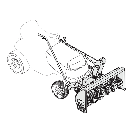
Two-Stage Snow Thrower Attachment — 190-032
WARNING
READ AND FOLLOW ALL SAFETY RULES AND INSTRUCTIONS IN THIS MANUAL
BEFORE ATTEMPTING TO OPERATE THIS MACHINE.
FAILURE TO COMPLY WITH THESE INSTRUCTIONS MAY RESULT IN PERSONAL INJURY.
MTD LLC, P.O. BOX 361131 CLEVELAND, OHIO 44136-0019
Printed In USA
Form No. 769-06335
(August 05, 2010)
Advertisement
Table of Contents

Related Manuals for MTD 190-032


Summary of Contents for MTD 190-032
- Page 1 READ AND FOLLOW ALL SAFETY RULES AND INSTRUCTIONS IN THIS MANUAL BEFORE ATTEMPTING TO OPERATE THIS MACHINE. FAILURE TO COMPLY WITH THESE INSTRUCTIONS MAY RESULT IN PERSONAL INJURY. MTD LLC, P.O. BOX 361131 CLEVELAND, OHIO 44136-0019 Printed In USA Form No. 769-06335...
-
Page 2: Table Of Contents
Choose from the options below: ◊ Visit us on the web at www.mtdproducts.com ◊ Call a Customer Support Representative at (800) 800-7310 or (330) 220-4683 ◊ Write us at MTD LLC • P.O. Box 361131 • Cleveland, OH • 44136-0019... -
Page 3: Important Safe Operation Practices
Important Safe Operation Practices WARNING! This symbol points out important safety instructions which, if not followed, could endanger the personal safety and/or property of yourself and others. Read and follow all instructions in this manual before attempting to operate this machine. Failure to comply with these instructions may result in personal injury. - Page 4 To avoid personal injury or property damage use extreme care Do not operate machine while under the influence of in handling gasoline. Gasoline is extremely flammable and the alcohol or drugs. vapors are explosive. Serious personal injury can occur when Muffler and engine become hot and can cause a burn.
-
Page 5: Maintenance And Storage
Clearing A Clogged Discharge Chute Snow thrower shave plates and skid shoes are subject to wear and damage. For your safety protection, frequently Hand contact with the rotating impeller inside the discharge check all components and replace with original equipment chute is the most common cause of injury associated with snow manufacturer’s (O.E.M.) parts only. -
Page 6: Assembly & Set-Up
Assembly & Set-Up Contents of Carton • One Auger Housing Assembly • One Upper Chute Crank Rod • Operator’s Manual • One Lift Handle Assembly • One Undercarriage Assembly • Two Self-adhesive Reflectors • One Hardware Pack Contents of Hardware Pack •... - Page 7 Manual PTO Undercarriage Assembly Setup Mounting The Undercarriage Assembly Position the undercarriage on the floor beneath your NOTE: There are two different styles of undercarriages, yours tractor close to the PTO cable. The small idler pulley should may differ slightly from the following images. be pointed towards the front of your tractor.
- Page 8 IMPORTANT: It will be helpful to have a second person assist you Attach the extension spring to the idler pulley. See Fig. 3-9. or a hydraulic floor lift to complete steps 3 through 6. Place the undercarriage assembly beneath the tractor and lift it up against the frame of the tractor.
- Page 9 Attaching The Chute Directional Control Attaching The Lift Handle Attach the chute directional control assembly to the upper Attach lift handle to lift bracket on the right side of auger lift link on the left side of the auger housing. Assemble with housing assembly with two hex screws and two flange nuts two hex screws and two saddle washers as illustrated in provided.
- Page 10 Attaching Support Tubes Position the auger housing assembly in front of the tractor. See Fig. 3-15. Lay the belt and support tubes on the Secure the left support tube to the front of the installation surface. undercarriage assembly with the clevis pin and hairpin clip removed earlier in step 2 of the mounting the undercarriage assembly section.
- Page 11 Routing The Upper Drive Belt (Tractor Models with an Electric PTO) Attach and route upper drive belt around spindle pulley and idler pulley found on undercarriage, electric PTO clutch and PTO idler pulley as illustrated in Fig. 3-18. Make sure that the belt is routed to the INSIDE of the belt keeper on the undercarriage idler pulley and the remaining keeper pins found around the spindle pulley.
- Page 12 Set-Up Lift Adjustment If the lift index rod, as seen in Fig. 3-23, doesn’t latch securely or Shear Pins the pivot release has too much slack in it, an adjustment can be made as follows: A pair of replacement auger shear pins and bow tie cotter pins are included with your snow thrower.
-
Page 13: Controls
Controls Trigger Control Chute Directional Control Lift Handle Figure 4-1 Chute Directional Control (See Fig. 4-1) Controls The chute directional control assembly is found on the left side WARNING! Be familiar with all controls and their of the tractor and includes both the chute tilt lever as well as the proper operation. -
Page 14: Operation
Operation Operation NEVER drive the tractor into a snow bank. The snow thrower attachment is not a dozer plow. The lift linkage WARNING! Read, understand, and follow all and/or the snow thrower drive system can be damaged as instructions and warnings on the tractor, the a result of “plowing”... - Page 15 NOTE: None of the kits in the table are included as standard equipment with snow thrower attachment OEM-190-032 and 190-032-101. Contact the retailer in which you purchased this equipment, or utilize the contact information on page 2 of this manual for availability and information regarding these kits.
-
Page 16: Maintenance
Maintenance WARNING: Auger Shaft Before lubricating, repairing, or inspecting, place tractor on a firm and level surface. At least once a season, remove the shear bolts on the auger Place the PTO in the disengaged (OFF) position, set shaft. Oil or spray lubricant inside and on the plastic bearings on the parking brake, shut engine off, and remove key the shaft and near the holes where the shear bolts were removed to prevent unintended starting. - Page 17 Notes...
-
Page 18: Illustrated Parts List
Model 190-032... - Page 19 Model 190-032 Part Number Description Part Number Description 918-04315 Auger Gear Box (Incl. Ref. 23-41) 721-0325 Grease Plug 721-0327 Grease Seal 684-0158-0637 Impeller Assembly, 12” 936-0351 Flat Washer, .76 x 1.5 x .030 684-0148-0637 Housing Assembly 936-0369 Flat Washer, .508 x 1.0 x .020...
- Page 20 Model 190-032 9 39 34 35...
- Page 21 Model 190-032 Part Number Description Part Number Description 783-1014A-0637 Drive Mounting Bracket 720-04039 Knob 911-0242 Spacer 784-5604A-0637 Chute Tilt Handle 741-0192 Flange Bearing w/ Flats 731-1313C Chute Tilt Cable Guide 756-1181A Drive Pulley, 7” 712-04063 Nylon Hex Lock Nut, 5/16-18 747-1192 Rod, 1/2 x 11.55...
- Page 22 Model 190-032 Part Number Description 911-0310 Clevis Pin, .5 x 1.18 911-1000 Belt Keeper Pin 712-04064 Nylon Hex Lock Nut, 1/4-20 912-3009 Hex Lock Nut, 5/16-18 914-0145 Click Pin, .092 x 1.64 714-0147 Internal Cotter Pin, .125 x 1.75 930-3000...
- Page 23 Model 190-032 Part Number Description 712-0417A Flange Nut 5/8-18 941-0919 Ball Bearing 750-1096 Spacer 738-0976 Spindle Shaft 756-0999 Deck Pulley 7” 756-1173 Pulley 3.75” 737-3000 Lube Fitting, 3/16...
- Page 24 MANUFACTURER’S LIMITED WARRANTY FOR The limited warranty set forth below is given by MTD LLC with b. Routine maintenance items such as lubricants, filters, blade respect to new merchandise purchased and used in the United States sharpening, tune-ups, brake adjustments, clutch adjustments,...
Need help?
Do you have a question about the 190-032 and is the answer not in the manual?
Questions and answers