
Related Manuals for Magnum MMG25FHZ


Summary of Contents for Magnum MMG25FHZ
- Page 1 GASOLINE POWERED GENERATOR MMG25FHZ - l l OPERATING MANUAL...
-
Page 2: Introduction
Occupational Safety and Health Association (OSHA) guidelines. Keep a copy of this manual with the unit at all times. Additional copies are available from Magnum Products LLC, or can be found at www.m-p-llc.com. An engine operator’s manual was also supplied with the unit at the time of shipment from the factory. -
Page 3: Table Of Contents
SHUTTING DOWN THE GENERATOR ....................21 MDC CONTROLLER INFORMATION DISPLAYS, FUNCTIONS AND RESET ........22 MAGNUM DIGITAL CONTROLLER (MDC) – GENERATOR OPERATIONAL STATUS ....22 MAGNUM DIGITAL CONTROLLER (MDC) - ALARM MANAGEMENT ..........22 MAGNUM DIGITAL CONTROLLER (MDC)- LIST OF POSSIBLE ALARMS/DESCRIPTIONS ..23 ENGINE CONTROLLER ........................ -
Page 4: Safety Notes
SAFETY NOTES This is the safety alert symbol. It is used to alert you to potential personal injury hazards. Obey all safety messages that follow this symbol to avoid possible injury or death. This manual contains DANGERS, WARNINGS, CAUTIONS, NOTICES and NOTES which must be followed to prevent the possibility of improper service, damage to the equipment, personal injury or death. -
Page 5: Engine Safety
ENGINE SAFETY Internal combustion engines present special hazards during operation and fueling! Failure to follow the safety guidelines described below could result in severe injury or death. Read and follow all safety warnings described in the engine operator's manual. A copy of this manual was supplied with the unit when it was shipped from the factory. -
Page 6: Towing Safety
If you believe your trailer has a defect which could cause a crash or could cause injury or death, you should immediately inform the National Highway Traffic Safety Administration (NHTSA) in addition to notifying Magnum Products LLC. If NHTSA receives similar complaints, it may open an investigation; and if it finds that a safety defect exists in a group of vehicles, it may order a recall and remedy campaign. -
Page 7: Safety Symbol Summary
SAFETY SYMBOL SUMMARY This equipment has been supplied with numerous safety and operating decals. These decals provide important operating instructions and warn of dangers and hazards. Replace any missing or hard-to-read decals and use care when washing or cleaning the unit. Decal placement and part numbers can be found in the parts section or parts manual included with your unit. -
Page 8: Specifications
Read all of the manuals included with this unit. Each manual details specific information regarding items such as set up, use and service requirements. SPECIFICATIONS ARE SUBJECT TO CHANGE WITHOUT NOTICE. MAGNUM MODEL MMG25FHZ Generator Specifications Engine Make/Brand.............. -
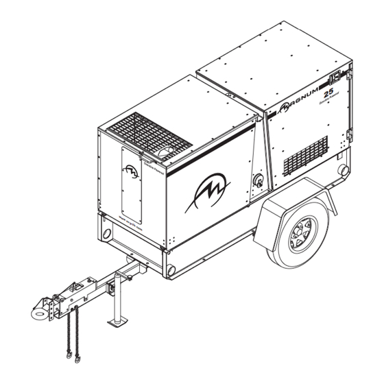
Page 9: Unit Dimensions
UNIT ID Tag MADE IN USA PRODUCTS LLC 215 Power Drive V.I.N. Tag Berlin, WI 54923 1-800-926-9768 Model Serial Number MANUFACTURED BY/FABRIQUE PAR: MAGNUM PRODUCTS LLC DATE: COLD INFL. PRESS./PRESS. Trailer ID Tag Mfg. Code GVWR/PNBV: DE GONF A FROID GAWR/PNBE TIRE/PNEU... -
Page 10: Component Locations
COMPONENT LOCATIONS... -
Page 11: Front Hood Operation
FRONT HOOD OPERATION WARNING Stay clear of hood and lift structure when opening and closing generator hoods. Personal injury may result. To open the front hood: 1. With your right hand, grip the handle located on the upper right side of the front panel. 2. -
Page 12: Rear Hood Operation
REAR HOOD OPERATION WARNING Stay clear of hood and lift structure when opening and closing generator hoods. Personal injury may result. To open the rear hood: 1. Open front hood. 2. Verify that the control door is completely closed and secure. 3. - Page 13 REAR HOOD OPERATION, CONTINUED WARNING Stay clear of hood and lift structure when opening and closing generator hoods. Personal injury may result. To close the rear hood: 1. Make sure the skid is free of debris and all personnel are clear of unit. 2.
-
Page 14: Main Control Panel Features
CHECK ENGINE 1. CONTROL PANEL LIGHT (OPTIONAL) 2. MAGNUM DIGITAL CONTROL PANEL: Controls and monitors engine and generator operation. See page 15 for more information. 3. CONTROL PANEL LIGHT SWITCH (OPTIONAL): Operates optional control panel light. 4. INTERIOR LIGHT SWITCH (OPTIONAL): Operates optional interior light. -
Page 15: Magnum Digital Controller (Mdc)
MAGNUM DIGITAL CONTROLLER (MDC) The Magnum Digital Controller (MDC) is an enhanced digital generator controller used to start, stop and monitor the operation of the generator and the engine. The controller constantly monitors vital generator and engine functions for a number of pre-programmed alarm and fault conditions. When a fault condition occurs, the engine will shut down automatically and the Liquid Crystal Display (LCD) window will display the fault that caused the shutdown;... -
Page 16: Generator Monitoring
• “AUTO ” Button Press this button to change from Manual starting mode to Automatic (remote) starting mode. • “ALARM CANCEL” Button When an alarm is activated, either visually or audibly, press this button to silence or cancel the alarm. •... -
Page 17: Engine Monitoring
ENGINE MONITORING Engine information is shown on the Liquid Crystal Display (LCD) window in a toggling manner with the Generator information after the first 60 seconds of operation and then every five seconds thereafter. The engine display screen will show oil pressure, engine coolant temperature, fuel level and battery voltage. •... -
Page 18: Fine Voltage Adjustment
FINE VOLTAGE ADJUSTMENT Upon start-up of the generator, the “Running” screen of the Magnum Digital Controller (MDC) will display “SENSING” and will countdown from 45 seconds to “0” Zero. This is a safety feature of the controller to protect the generator from over or under voltage upon start-up. -
Page 19: Generator Start Up
GENERATOR START UP Before starting the generator, carefully read over the pre-start check list. Make sure that all of the items are checked before trying to start the generator. This check list applies to both manual and remote starting of the generator. PRE- START CHECK LIST Make sure the control ON/OFF toggle switch is in the OFF “O”... - Page 20 4. Press the green “ENGINE START” button. The Prestart (Preheat) screen will be displayed (if equipped) and a countdown will begin from 20 seconds to 0. 5. The Starting screen will be displayed. The engine will crank and start running. 6.
-
Page 21: Auto" (Remote) Starting Of The Generator
Attach a jumper wire (minimum 16 gauge) across the two terminals on the remote start terminal block. This applies a ground to the Magnum Digital Controller (MDC) to close the starting circuit contacts. The engine should crank, start and run. -
Page 22: Mdc Controller Information Displays, Functions And Reset
MDC CONTROLLER INFORMATION DISPLAYS, FUNCTIONS AND RESET The Magnum Digital Controller (MDC) constantly monitors vital generator and engine functions for a number of operation, alarm and fault conditions. When a fault condition occurs, the engine will shut down automatically and the Liquid Crystal Display (LCD) window will show the fault that has caused the shut down. -
Page 23: Magnum Digital Controller (Mdc)- List Of Possible Alarms/Descriptions
MAGNUM DIGITAL CONTROLLER (MDC)- LIST OF POSSIBLE ALARMS/DESCRIPTIONS Shut down and warning fault conditions and the displayed message are described in the following table: Information on Binary Events Protection Output Specification Type Available Description 1 AnInIOM Sd Shutdown alarm configurable on the input of IG-IOM/IGS-PTM. -
Page 24: Engine Controller
When an operation, alarm or fault condition occurs, the Liquid Crystal Display (LCD) window on the Magnum Digital Controller (MDC) will alert the operator either visually or audibly. Press the “ ” Scroll-Up button (on the diagnostic keypad) to view the “Alarm List.”... -
Page 25: Magnum Digital Controller (Mdc) - History
MAGNUM DIGITAL CONTROLLER (MDC) – HISTORY The Magnum Digital Controller (MDC) controller stores a record of each important event into the history file of the controller. The history file seats 118 records. When the history file is full, the oldest records are removed. -
Page 26: Resetting Of The "Time To Service" Reminder
RESETTING OF THE “TIME TO SERVICE” REMINDER The Magnum Digital Controller (MDC) will display the message “WrnServiceTime” when the unit is due for maintenance or service. The maintenance or service interval is set at 250 hours of engine running time. Once the unit has been serviced, the “ServiceTime”... -
Page 27: Low Coolant Level Shutdown
LOW COOLANT LEVEL SHUTDOWN 1. Allow the engine to cool. 2. Check the coolant level in the radiator. Remove the radiator cap and add coolant until it is 3/4” below the filler neck. Secure the radiator cap back into its original position. 3. -
Page 28: Generator Output Connection Lugs
GENERATOR OUTPUT CONNECTION LUGS The generator is equipped with connection lugs behind the lug door next to the customer convenience outlets. The lugs provide connection points for attachment of external loads to the generator. A large decal on the inside of the connection lug door details the proper connections for selected voltages. -
Page 29: Generator Cam Lock Connections (Optional)
GENERATOR CAM LOCK CONNECTIONS (OPTIONAL) The generator may be equipped with cam lock connections located behind the lug door next to the customer convenience outlets. These receptacles provide connection points for attachment of external loads to the generator. A large decal on the inside of the connection lug door details the proper connections for selected voltages. WARNING It is HIGHLY RECOMMENDED that only a trained and licensed electrician perform any wiring and related connections to the generator. -
Page 30: Voltage Selector Switch
VOLTAGE SELECTOR SWITCH The voltage selector switch is located under the control panel, next to the output connection lugs. The selector switch is a three position switch that mechanically changes the connections between the generator output leads and the connection lugs or optional cam lock connectors. Voltage ranges are selected by rotating the handle on the switch to the desired voltage. -
Page 31: 4-Position Voltage Selector Switch (Optional)
4-POSITION VOLTAGE SELECTOR SWITCH (OPTIONAL) The voltage selector switch is located under the control panel, next to the connection lugs. This optional selector switch is a four position switch that mechanically changes the connection between the generator output leads and the connection lugs or optional cam lock connectors. -
Page 32: Emergency Stop Switch
The regulator has three screwdriver adjustable potentiometers that may be adjusted for voltage, stability and under frequency (U/F). The voltage regulator on your unit is adjusted before shipment from the factory. Contact Magnum Products LLC for additional information before attempting to adjust the voltage regulator. -
Page 33: Customer Convenience Outlets
CUSTOMER CONVENIENCE OUTLETS The generator is equipped with four convenience outlets. The large outlets are 240/120 VAC twist-lock receptacles rated at 50A each. The smaller outlets are 120 VAC duplex receptacles rated at 20A each with ground fault interrupt (GFCI) protection. These receptacles are not routed through the main circuit breaker. -
Page 34: Remote Start Terminal Block
REMOTE START TERMINAL BLOCK The remote start terminal block is located between the two 240/120V VAC twist-lock convenience outlets. It provides a connection for installation of a remote start switch which will allow the generator to be started by a remote dry-contact closure switch. Before pressing the AUTO button, verify the contacts on any remote switch linked to the generator are OPEN. -
Page 35: Engine Break-In Requirements
ENGINE BREAK-IN REQUIREMENTS Note: During the first 20 hours of operation, avoid long periods of no load or sustained maximum load operation. If the generator is to run for longer than five minutes without a load, shut the generator down. The engine is supplied with engine break-in oil from the factory. -
Page 36: Daily Maintenance Checks
DAILY MAINTENANCE CHECKS Check the engine oil level daily before starting engine. DO NOT start the generator if the oil level is below the ADD mark on the dipstick. The normal operating level for the engine oil is anywhere in the crosshatch pattern between the FULL and ADD markings. -
Page 37: Lifting The Generator
LIFTING THE GENERATOR A large central lifting eye is located on the top of the generator. The eye is connected to a central lifting frame inside the unit. Attach a sling or hook directly to the lifting eye only if the devices are in good condition and the equipment being used to raise the unit has sufficient capacity. -
Page 38: Trailer Wiring Diagram
TRAILER WIRING DIAGRAM ELECTRIC BRAKE WIRING DIAGRAM BREAK AWAY SW + BATT - TO BRAKES GREEN RIGHT TURN/STOP YELLOW LEFT TURN/STOP BROWN TAIL/MARKER WHITE GROUND... -
Page 39: Ac Wiring Diagram
AC WIRING DIAGRAM 240V 240V 50A BREAKER RCPT. 240V 240V 50A BREAKER RCPT. -
Page 40: Ac Wiring Diagram: 4-Position Phase Switch
AC WIRING DIAGRAM: 4-POSITION PHASE SWITCH 240V 240V 50A BREAKER RCPT. 240V 240V 50A BREAKER RCPT. -
Page 41: Dc Wiring Diagram
DC WIRING DIAGRAM... -
Page 42: Service Log
SERVICE LOG OIL GRADE AND TYPE: ____________________________ BRAND: __________________________________ COOLANT MIXTURE: ______________________________ BRAND: __________________________________ __________________________________________________________________________________________ __________________________________________________________________________________________ __________________________________________________________________________________________ __________________________________________________________________________________________ __________________________________________________________________________________________ __________________________________________________________________________________________ __________________________________________________________________________________________ __________________________________________________________________________________________ __________________________________________________________________________________________ __________________________________________________________________________________________... -
Page 43: Notes
NOTES: __________________________________________________________________________________________ __________________________________________________________________________________________ __________________________________________________________________________________________ __________________________________________________________________________________________ __________________________________________________________________________________________ __________________________________________________________________________________________ __________________________________________________________________________________________ __________________________________________________________________________________________ __________________________________________________________________________________________ __________________________________________________________________________________________ __________________________________________________________________________________________ __________________________________________________________________________________________ __________________________________________________________________________________________ __________________________________________________________________________________________ __________________________________________________________________________________________ __________________________________________________________________________________________ __________________________________________________________________________________________ __________________________________________________________________________________________ __________________________________________________________________________________________ __________________________________________________________________________________________ __________________________________________________________________________________________ __________________________________________________________________________________________ __________________________________________________________________________________________ __________________________________________________________________________________________ __________________________________________________________________________________________ __________________________________________________________________________________________ __________________________________________________________________________________________ __________________________________________________________________________________________ __________________________________________________________________________________________ __________________________________________________________________________________________... - Page 44 REV: ORG (WD) PART NO:27459 05.12.09...
Need help?
Do you have a question about the MMG25FHZ and is the answer not in the manual?
Questions and answers