Table of Contents
Advertisement
Advertisement
Table of Contents

Related Manuals for Magnum MMG 150


Summary of Contents for Magnum MMG 150
- Page 1 DIESEL GENERATOR MMG 150 • MMG 170 • MMG 235 OPERATING MANUAL...
-
Page 2: Introduction
Occupational Safety and Health Association (OSHA) guidelines. Keep a copy of this manual with the unit at all times. Additional copies are available from Magnum Products LLC, or can be found at www.m-p-llc.com. An engine operator’s manual was also supplied with the unit at the time of shipment from the factory. -
Page 3: Table Of Contents
TROUBLESHOOTING AUTOMATIC SHUTDOWN CONDITIONS ............. 29 GENERATOR OUTPUT CONNECTION LUGS ................... 31 GENERATOR CAM LOCK CONNECTIONS (OPTIONAL) ..............32 VOLTAGE SELECTOR SWITCH (MMG 150 & MMG 170 ONLY) ............33 4-POSITION VOLTAGE SELECTOR SWITCH (OPTIONAL) ............. 34 CHANGING OUTPUT VOLTAGE (MMG 235 ONLY) ................. 35 EMERGENCY STOP SWITCH ...................... -
Page 4: Safety Notes
SAFETY NOTES This is the safety alert symbol. It is used to alert you to potential personal injury hazards. Obey all safety messages that follow this symbol to avoid possible injury or death. This manual contains DANGERS, WARNINGS, CAUTIONS, NOTICES and NOTES which must be followed to prevent the possibility of improper service, damage to the equipment, personal injury or death. -
Page 5: Engine Safety
ENGINE SAFETY Internal combustion engines present special hazards during operation and fueling! Failure to follow the safety guidelines described below could result in severe injury or death. Read and follow all safety warnings described in the engine operator's manual. A copy of this manual was supplied with unit when it was shipped from the factory. -
Page 6: Towing Safety
If you believe your trailer has a defect which could cause a crash or could cause injury or death, you should immediately inform the National Highway Traffic Safety Administration (NHTSA) in addition to notifying Magnum Products LLC. If NHTSA receives similar complaints, it may open an investigation; and if it finds that a safety defect exists in a group of vehicles, it may order a recall and remedy campaign. -
Page 7: Unit Serial Number Locations
UNIT ID Tag PRODUCTS LLC MADE IN USA 215 Power Drive Berlin, WI 54923 1-800-926-9768 V.I.N. Tag Model Serial Number DATE: MANUFACTURED BY/FABRIQUE PAR: MAGNUM PRODUCTS LLC COLD INFL. PRESS./PRESS. Mfg. Code GVWR/PNBV: DE GONF A FROID GAWR/PNBE TIRE/PNEU RIM/JANTE KPA(PSI/LPC) SGL/DUAL amb. -
Page 8: Safety Symbol Summary
SAFETY SYMBOL SUMMARY This equipment has been supplied with numerous safety and operating decals. These decals provide important operating instructions and warn of dangers and hazards. Replace any missing or hard-to-read decals and use care when washing or cleaning the unit. Decal placement and part numbers can be found in the parts section or parts manual included with your unit. -
Page 9: Specifications
Read all of the manuals included with this unit. Each manual details specific information regarding items such as set up, use and service requirements. MAGNUM MODEL MMG 150 MMG 150 Super Start Engine Make/Brand..............John Deere........John Deere Model ...............PE6068HF285......PE6068HF285 Horsepower - prime hp (kW) ........180 (134)........ - Page 10 Read all of the manuals included with this unit. Each manual details specific information regarding items such as set up, use and service requirements. MAGNUM MODEL MMG 170...
- Page 11 Read all of the manuals included with this unit. Each manual details specific information regarding items such as set up, use and service requirements. MAGNUM MODEL MMG 235...
-
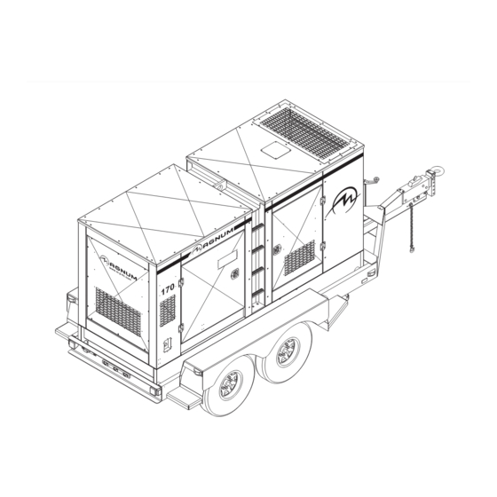
Page 12: Unit Dimensions
UNIT DIMENSIONS Read this manual carefully before attempting to use this generator. The potential for property damage, personal injury or death exists if this equipment is misused or installed incorrectly. Read all of the manuals included with this unit. Each manual details specific information regarding items such as set up, use and service requirements. Dimensions (L x W x H) Skid Mounted in (m) ..........132 x 50 x 77 (3.35 x 1.27 x 1.96) Trailer Mounted in (m) ..........210 x 86 x 93 (5.33 x 2.18 x 2.36) -
Page 13: Service Locations
SERVICE LOCATIONS... -
Page 14: Main Control Panel Features, Standard
MAIN CONTROL PANEL FEATURES, STANDARD... - Page 15 15. MAIN CIRCUIT BREAKER FOR CONNECTION LUGS: The MMG 150 has one 600A breaker, the MMG 170 a 700A breaker and the MMG 235 has an 800A breaker.
-
Page 16: Main Control Panel Features, With Optional Cam Locks
MAIN CONTROL PANEL FEATURES, WITH OPTIONAL CAM LOCKS OPERATION CONTROL CONTROL MAN AUT MANUAL AUTO ENGINE ENGINE Ready START START 0.00 CONTROL CONTROL ALARM FAULT ENGINE ENGINE CANCEL RESET STOP STOP DIAGNOSTICS STATUS PAGE ALARM/FAULT WARNING SELECT READY/MANUAL READY/AUTO ENTER RUNNING SUPPLYING LOAD... - Page 17 16. CIRCUIT BREAKERS FOR 120/240V CONVENIENCE OUTLETS, 50A (3) 17. CIRCUIT BREAKERS FOR 120V GFCI CONVENIENCE OUTLETS, 20A (2) 18. MAIN CIRCUIT BREAKER FOR CONNECTION LUGS: The MMG 150 has one 600A breaker, the MMG 170 a 700A breaker and the MMG 235 has an 800A breaker.
-
Page 18: Digital Controller Features And Functions
MAGNUM DIGITAL CONTROLLER (MDC) The Magnum Digital Controller (MDC) is an enhanced digital generator controller used to start, stop and monitor the operation of the generator and the engine. The controller constantly monitors vital generator and engine functions for a number of pre-programmed alarm and fault conditions. When a fault condition occurs, the engine will shut down automatically and the Liquid Crystal Display (LCD) window will display the fault that caused the shutdown;... -
Page 19: Generator Monitoring
• “AUTO ” Button Press this button to change from Manual starting mode to Automatic (remote) starting mode. • “ALARM CANCEL” Button When an alarm is activated, either visually or audibly, press this button to silence or cancel the alarm. •... -
Page 20: Engine Monitoring
ENGINE MONITORING Engine information is shown on the Liquid Crystal Display (LCD) window in a toggling manner with the Generator information after the first 60 seconds of operation and then every five seconds thereafter. The engine display screen will show oil pressure, engine coolant temperature, fuel level and battery voltage. •... -
Page 21: Fine Voltage Adjustment
The controller stores up to 118 codes. When full, the controller will automatically remove the oldest file. These codes will not be lost when the control power toggle switch is powered off. FINE VOLTAGE ADJUSTMENT Upon start-up of the generator, the “Running” screen of the Magnum Digital VOLTAGE CONTROL Controller (MDC) will display “SENSING”... -
Page 22: Generator Start Up
GENERATOR START UP Before starting the generator, carefully read over the pre-start check list. Make sure that all of the items are checked before trying to start the generator. This check list applies to both manual and remote starting of the generator. PRE- START CHECK LIST Make sure the control ON/OFF toggle switch is in the OFF “O”... - Page 23 4. Press the green “ENGINE START” button. The Prestart (Preheat) screen will be displayed (if equipped) and a countdown will begin from 20 seconds to 0. 5. The Starting screen will be displayed. The engine will crank and start running. 6.
-
Page 24: Auto" (Remote) Starting Of The Generator
Attach a jumper wire (minimum 16 gauge) across the two terminals on the remote start terminal block. This applies a ground to the Magnum Digital Controller (MDC) to close the starting circuit contacts. The engine should crank, start and run. -
Page 25: Magnum Digital Controller Information Displays, Functions And Reset
MAGNUM DIGITAL CONTROLLER INFORMATION DISPLAYS, FUNCTIONS AND RESET The Magnum Digital Controller (MDC) constantly monitors vital generator and engine functions for a number of operation, alarm and fault conditions. When a fault condition occurs, the engine will shut down automatically and the Liquid Crystal Display (LCD) window will show the fault that has caused the shut down. -
Page 26: Magnum Digital Controller (Mdc)- List Of Possible Alarms/Descriptions
MAGNUM DIGITAL CONTROLLER (MDC)- LIST OF POSSIBLE ALARMS/DESCRIPTIONS Shut down and warning fault conditions and the displayed message are described in the following table: Information on Binary Events Protection Output Specification Type Available Description 1 AnInIOM Sd Shutdown alarm configurable on the input of IG-IOM/IGS-PTM. -
Page 27: John Deere Ecu Information Displays And Functions
The generator voltage is unbalanced more than the value of 28 Vgen unbal Volt unbal setpoint. 29 Wrn ECU Alarm ECU alarm list is not empty. 30 Wrn RA15 fail Warning alarm in case of lost connection to IGL-RA15 module. The period for servicing is set by the NextServTime setpoint. -
Page 28: Magnum Digital Controller (Mdc) - History
MAGNUM DIGITAL CONTROLLER (MDC) – HISTORY The Magnum Digital Controller (MDC) stores a record of each important event into the history file of the controller. The history file seats 118 records. When the history file is full, the oldest records are removed. -
Page 29: Resetting Of The "Time To Service" Reminder
RESETTING OF THE “TIME TO SERVICE” REMINDER The Magnum Digital Controller (MDC) will display the message “WrnServiceTime” when the unit is due for maintenance or service. The maintenance or service interval is set at 250 hours of engine running time. Once the unit has been serviced, the “ServiceTime”... - Page 30 HIGH COOLANT TEMPERATURE SHUTDOWN 1. Check the coolant level in the overflow jug. 2. Restart the engine and read the coolant temperature to verify High Coolant Temperature Shutdown. Stop the engine immediately if the coolant temperature is 230°F or more. 3.
-
Page 31: Generator Output Connection Lugs
GENERATOR OUTPUT CONNECTION LUGS The generator is equipped with connection lugs behind the lug box door located on the lower portion of the control box. The lugs provide connection points for attachment of external loads to the generator. A large decal on the inside of the connection lug door details the proper connections for selected voltages. -
Page 32: Generator Cam Lock Connections (Optional)
GENERATOR CAM LOCK CONNECTIONS (OPTIONAL) The generator may be equipped with cam lock connections behind the door on the right side of the customer convenience outlets. These receptacles provide connection points for attachment of external loads to the generator. A large decal on the inside of the connection lug door details the proper connections for selected voltages. WARNING It is HIGHLY RECOMMENDED that only a trained and licensed electrician perform any wiring and related connections to the generator. -
Page 33: Voltage Selector Switch (Mmg 150 & Mmg 170 Only)
VOLTAGE SELECTOR SWITCH (MMG 150 & MMG 170 ONLY) The voltage selector switch is located on a panel attached to the generator behind the door located next to the fuel tank filler. The selector switch is a three position switch that mechanically changes the connections between the generator output leads and the connection lugs on the main control panel. -
Page 34: 4-Position Voltage Selector Switch (Optional)
4-POSITION VOLTAGE SELECTOR SWITCH (OPTIONAL) The optional four position voltage selector switch is located on a panel attached to the generator behind the door located next to the fuel tank filler. The voltage selector is a four position switch that mechanically changes the connections between the generator output leads and the connection lugs on the main control panel. -
Page 35: Changing Output Voltage (Mmg 235 Only)
CHANGING OUTPUT VOLTAGE (MMG 235 ONLY) The output voltage can be changed by moving the shorting (link) board in the generator reconnect box. The reconnect box is located on the top of the generator. Before attempting to change the output voltage, shut the generator down and make sure that the main circuit breaker and the control power switch are in the off “O”... -
Page 36: Emergency Stop Switch
The regulator has three screwdriver adjustable potentiometers that may be adjusted for voltage, stability and under frequency (U/F). The voltage regulator on your unit is adjusted before shipment from the factory. Contact Magnum Products LLC for additional information before attempting to adjust the voltage regulator. -
Page 37: Customer Convenience Outlets
CUSTOMER CONVENIENCE OUTLETS The generator is equipped with five convenience outlets. The large outlets are 240/120 VAC twist-lock receptacles rated at 50 A each. The smaller outlets are 120 VAC duplex receptacles rated at 20 A each with ground fault interrupt (GFCI) protection. -
Page 38: Transfer Switch
TRANSFER SWITCH When the generator is used as a standby power supply, it must be equipped with a transfer switch which isolates it from the utility’s distribution system. A transfer switch is designed to transfer electrical loads from the normal power source (utility) to the emergency power source (generator) when normal voltage falls below a prescribed level. -
Page 39: Engine And Generator Maintenance
WARNING It is strongly recommended that ONLY a licensed electrician perform any wiring and any related connections to the generator. Installation should be in compliance of the National Electric Code (NEC) as well as any state or local codes or regulations. Failure to follow these procedures could result in property damage, personal injury or death. -
Page 40: Engine Break-In Requirements
ENGINE BREAK-IN REQUIREMENTS Note: During the first 20 hours of operation, avoid long periods of no load or sustained maximum load operation. If the generator is to run for longer than five minutes without a load, shut the generator down. The engine is supplied with engine break-in oil from the factory. -
Page 41: Lifting The Generator
LIFTING THE GENERATOR CENTRAL LIFT EYE A large central lifting eye is located on the top of the generator. The eye is connected to a central lifting frame inside the unit. Attach a sling or hook directly to the lifting eye only if the devices are in good condition and the equipment being used to raise the unit has sufficient capacity. -
Page 42: Trailer Wiring Diagram
TRAILER WIRING DIAGRAM TRAILER PLUG AMBER AMBER MARKER MARKER LAMP LAMP AMBER AMBER MARKER MARKER LAMP LAMP FENDER FENDER IDENTIFICATION MARKER MARKER LIGHT BAR LAMP LAMP PLATE LAMP STOP-TURN STOP-TURN SIGNAL LAMP SIGNAL LAMP (LEFT) (RIGHT) -
Page 43: Electric Brake Wiring Harness
ELECTRIC BRAKE WIRING HARNESS... -
Page 44: Ac Wiring Diagram: Mmg150-Mmg170
AC WIRING DIAGRAM: MMG150-MMG170... -
Page 45: Ac Wiring Diagram: Mmg150-Mmg170 - 4-Position Phase Switch
AC WIRING DIAGRAM: MMG150-MMG170 - 4-POSITION PHASE SWITCH... -
Page 46: Ac Wiring Diagram: Mmg235
AC WIRING DIAGRAM: MMG235... -
Page 47: Ac Wiring Diagram: Mmg235 - 4-Position Phase Switch
AC WIRING DIAGRAM: MMG235 - 4-POSITION PHASE SWITCH... -
Page 48: Dc Wiring Diagram: Mmg150-Mmg170
DC WIRING DIAGRAM: MMG150-MMG170... -
Page 49: Dc Wiring Diagram: Mmg235
DC WIRING DIAGRAM: MMG235... -
Page 50: Service Log
SERVICE LOG OIL GRADE AND TYPE: ____________________________ BRAND:___________________________________ COOLANT MIXTURE: ______________________________ BRAND:___________________________________ __________________________________________________________________________________________ __________________________________________________________________________________________ __________________________________________________________________________________________ __________________________________________________________________________________________ __________________________________________________________________________________________ __________________________________________________________________________________________ __________________________________________________________________________________________ __________________________________________________________________________________________ __________________________________________________________________________________________ __________________________________________________________________________________________... -
Page 51: Notes
NOTES __________________________________________________________________________________________ __________________________________________________________________________________________ __________________________________________________________________________________________ __________________________________________________________________________________________ __________________________________________________________________________________________ __________________________________________________________________________________________ __________________________________________________________________________________________ __________________________________________________________________________________________ __________________________________________________________________________________________ __________________________________________________________________________________________ __________________________________________________________________________________________ __________________________________________________________________________________________ __________________________________________________________________________________________ __________________________________________________________________________________________ __________________________________________________________________________________________ __________________________________________________________________________________________ __________________________________________________________________________________________ __________________________________________________________________________________________ __________________________________________________________________________________________ __________________________________________________________________________________________ __________________________________________________________________________________________ __________________________________________________________________________________________ __________________________________________________________________________________________ __________________________________________________________________________________________ __________________________________________________________________________________________ __________________________________________________________________________________________ __________________________________________________________________________________________ __________________________________________________________________________________________ __________________________________________________________________________________________ __________________________________________________________________________________________... - Page 52 REV: D (WD) PART NO: 26277 03.25.09...
Need help?
Do you have a question about the MMG 150 and is the answer not in the manual?
Questions and answers
Generator runs for 45 seconds and shuts down with Alarms/faults light on and warning light on. Gen Freq 49.4 Hz, L1 27V, L2 28V, L3 28V L12 47V, L23 48V, L31 48V. how can I fix this?
To fix a Magnum MMG 150 generator that runs for 45 seconds and then shuts down with alarms and warning lights, follow these steps:
1. Check the LCD Display: The Magnum Digital Controller (MDC) will show the fault or alarm that caused the shutdown on the LCD window. Identify the specific fault condition.
2. Resolve the Fault Condition: Address the issue indicated by the fault message. For example:
- If it is a fuel issue, ensure there is enough fuel and the fuel system is functioning properly.
- If it is an overheating issue, verify that the cooling system is working.
- If it is an electrical fault, inspect the connections and components.
3. Reset the Controller: Once the fault is resolved, press the “FAULT RESET” button on the MDC to reset the system.
4. Test the Generator: Restart the generator and confirm that it runs without shutting down.
If the problem persists, consult the manual for additional troubleshooting steps related to the specific fault or contact a qualified technician.
This answer is automatically generated