
Related Manuals for Magnum MMG75CAN6


Summary of Contents for Magnum MMG75CAN6
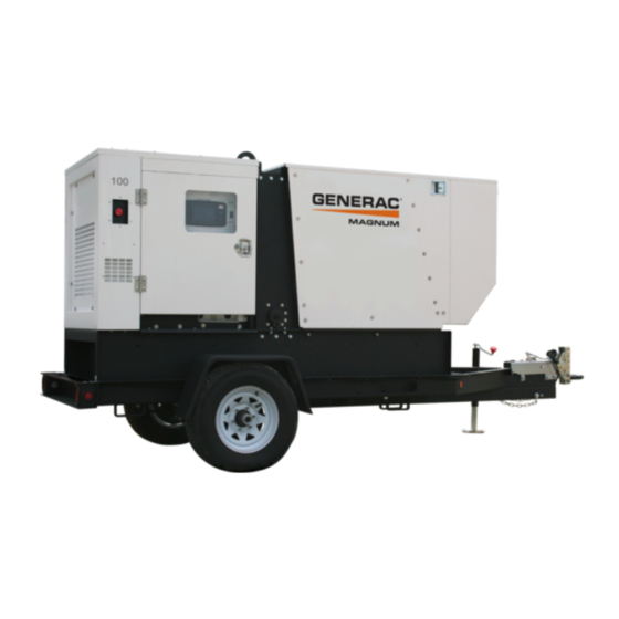
- Page 1 POWER PRODUCTS LLC DIESEL GENERATOR MMG75CAN6 • MMG100CAN6 - l l OPERATING MANUAL Parts manuals available online! www.m-p-llc.com...
-
Page 2: Introduction
Occupational Safety and Health Association (OSHA) guidelines. Keep a copy of this manual with the unit at all times. Additional copies are available from Magnum Power Products LLC, or can be found at www.m-p-llc.com. An engine operator’s manual is supplied with the unit at the time of shipment from the factory. -
Page 3: Table Of Contents
SHUTTING DOWN........................... 23 MDC CONTROLLER INFORMATION DISPLAYS, FUNCTIONS, AND RESET ......23 MAGNUM DIGITAL CONTROLLER (MDC) - GENERATOR OPERATIONAL STATUS ....23 MAGNUM DIGITAL CONTROLLER (MDC) - ALARM MANAGEMENT........... 24 MAGNUM DIGITAL CONTROLLER (MDC) - LIST OF ALARMS ............ 24 JOHN DEERE ECU INFORMATION DISPLAYS AND FUNCTIONS .......... - Page 4 AUXILIARY FUEL TANK OPTION ....................40 FUEL TRANSFER PUMP OPTION....................40 AC WIRING DIAGRAM - MMG75CAN6................... 41 AC WIRING DIAGRAM - MMG100CAN6..................42 AC WIRING DIAGRAMS FOR OPTIONAL EQUIPMENT ..............43 DC WIRING DIAGRAM ........................44 DC WIRING DIAGRAMS FOR OPTIONAL EQUIPMENT..............45 WIRING BLOCK DIAGRAM - DEDICATED 12 LEAD GENERATORS OPTION ......
-
Page 5: Safety Notes
SAFETY NOTES This is the safety alert symbol. It is used to alert you to potential personal injury hazards. Obey all safety messages that follow this symbol to avoid possible injury or death. This manual contains DANGERS, WARNINGS, CAUTIONS, NOTICES and NOTES which must be followed to prevent the possibility of improper service, damage to the equipment, personal injury or death. -
Page 6: Engine Safety
ENGINE SAFETY Internal combustion engines present special hazards during operation and fueling! Failure to follow the safety guidelines described below could result in severe injury or death. Read and follow all safety warnings described in the engine operator's manual. A copy of this manual was supplied with unit when it was shipped from the factory. -
Page 7: Towing Safety
REPORTING TRAILER SAFETY DEFECTS If you believe your trailer has a defect which could cause a crash or could cause injury or death, you should immediately inform the National Highway Traffic Safety Administration (NHTSA) in addition to notifying Magnum Power Products LLC. -
Page 8: Safety Symbol Summary
SAFETY SYMBOL SUMMARY This equipment has been supplied with numerous safety and operating decals. These decals provide important operating instructions and warn of dangers and hazards. Replace any missing or hard-to-read decals and use care when washing or cleaning the unit. Decal placement and part numbers can be found in the parts manual. Below is a summary of the intended meanings for the symbols used on the decals. -
Page 9: Specifications - Mmg75Can6
SPECIFICATIONS - MMG75CAN6 Read this manual carefully before attempting to use this generator. The potential for property damage, personal injury or death exists if this equipment is misused or installed incorrectly. Read all of the manuals included with this unit. -
Page 10: Specifications - Mmg100Can6
Read all of the manuals included with this unit. Each manual details specific information regarding items such as setup, use and service requirements. SPECIFICATIONS ARE SUBJECT TO CHANGE WITHOUT NOTICE. MAGNUM MODEL MMG100CAN6 Engine Make/Brand..........................John Deere... -
Page 11: Unit Dimensions
Read all of the manuals included with this unit. Each manual details specific information regarding items such as setup, use and service requirements. SPECIFICATIONS ARE SUBJECT TO CHANGE WITHOUT NOTICE. MAGNUM MODELS MMG75CAN6/MMG100CAN6 Dimensions (L x W x H) Skid Mounted in (m) ..................... -
Page 12: Unit Serial Number Locations
Mfg. Code VIN Tag Skidded WT (lbs/kg) rpm/freq TIRE AND LOADING INFORMATION 1 ph. 1.0PF 3 ph. .8PF 3 ph. 1.0PF MANUFACTURED BY/FABRIQUE PAR: Magnum Power Products LLC DATE: 00/0000 GVWR/PNBV: 000KG (0000LBS) COLD INF. PRESS./ RENSEIGNEMENTS SUR LES PRESS. DE... -
Page 13: Component Locations
COMPONENT LOCATIONS Central Radiator Lift Point Access Panel Voltage Selector Switch Access Fuel Fill Engine Access LEFT SIDE Engine Exhaust Emergency Engine Stop Access Engine Battery Access Control Panel Access Radiator Drain Port RIGHT SIDE Oil Drain Port... -
Page 14: Main Control Panel Features
MAIN CONTROL PANEL FEATURES MAN AUT Ready 0.00 CAUTION Do not use 120V GFCI outlets when generator at 480 or 600 volts. Equipment damage or personal injury may result. CAUTION Do not use 240V twist lock outlets when generator at 600 volts. - Page 15 5. AUXILIARY LIGHT SWITCHES: These switches operate optional control panel and interior lights. 6. AIR FILTER METER: This gauge shows the condition of the air filter when the engine is running. 7. MAGNUM DIGITAL CONTROLLER (MDC): Refer to “Magnum Digital Controller (MDC)” on page 8.
-
Page 16: Magnum Digital Controller (Mdc)
MAGNUM DIGITAL CONTROLLER (MDC) The MDC is an enhanced digital generator controller used to start, stop and monitor the operation of the generator and the engine. The controller constantly monitors vital generator and engine functions for a number of pre- programmed alarm and fault conditions. -
Page 17: Generator Monitoring
• “MANUAL ” button: Press this button to change from the automatic (remote) starting mode to manual starting mode. • “AUTO ” button: Press this button to change from manual starting mode to automatic (remote) starting mode. • “ALARM CANCEL” button: When an alarm is activated, either visually or audibly, press this button to silence or cancel the alarm. -
Page 18: Engine Monitoring
ENGINE MONITORING Engine information is shown on the Liquid Crystal Display (LCD) window in a toggling manner with the generator information after the first 60 seconds of operation and then every five seconds thereafter. The Engine Display screen will show oil pressure, engine coolant temperature, fuel level and battery voltage. •... -
Page 19: Wet Stacking
FINE VOLTAGE ADJUSTMENT Upon startup of the generator, the “Running” screen of the Magnum Digital Voltage Controller (MDC) will display “V Detect” and will countdown from 45 seconds to... -
Page 20: Pre-Start Checklist
This screw turns a rheostat that will provide an increase (“+”) or a decrease (“-”) in the generator output voltage as displayed on the generator display screen on the MDC. If the voltage is increased or decreased too fast or too slow, the unit will automatically shut down. -
Page 21: Manual Starting Of The Generator
MANUAL STARTING OF THE GENERATOR 1. Move the “CONTROL ON/OFF” toggle switch to the “CONTROL ON/I” position. DANGER CARBON MONOXIDE: USING A GENERATOR INDOORS CAN KILL YOU IN MINUTES! 2. The Liquid Crystal Display (LCD) window will quickly display system information, all Light Emitting Diodes (LED’s) will flash. -
Page 22: Auto" (Remote) Starting Of The Generator
6. The “Running” screen will display. Note: It may take a few seconds for the engine to run smoothly and reach its governed operating speed. The 45 second “V detect” time delay will start to countdown. 7. The LCD window will then toggle from the “Running” screen to the generator display screen and then to the engine display screen. -
Page 23: Shutting Down
Attach a jumper wire (minimum 16 gauge) across the two terminals on the remote start terminal block. This applies a ground to the Magnum Digital Controller (MDC) to close the starting circuit contacts. The engine should crank, start and run. -
Page 24: Magnum Digital Controller (Mdc) - Alarm Management
Shutdown (SD) outputs GCB CLOSE/OPEN, FUEL, SOLENOID, STARTER and PRESTART to stop the engine immediately. MAGNUM DIGITAL CONTROLLER (MDC) - LIST OF ALARMS Shutdown and warning fault conditions and the displayed message are described in the following table: Information on... -
Page 25: John Deere Ecu Information Displays And Functions
Information on Events Protection Binary Output Description Specification Type Available Fuel level is smaller than Wrn Fuel Level setpoint 11 Fuel Level Wrn (15%). 12 GCB fail Failure of the generator circuit breaker. 13 Igen unbl The generator current is unbalanced. 14 Low BackupBatt RTC backup battery is flat (low). -
Page 26: Magnum Digital Controller (Mdc) - History
*Note: The Suspect Parameter Number (SPN) is displayed as “FC” on the bottom left of the LCD window. See Figure 1. MAGNUM DIGITAL CONTROLLER (MDC) - HISTORY The MDC stores a record of each important event in the history file of the controller. The history file seats 117 records. -
Page 27: Adjusting The Display Backlighting
IL-NT analog input 2 value (default: water temperature) ADJUSTING THE DISPLAY BACKLIGHTING The brightness on the Liquid Crystal Display (LCD) window may be adjusted by the operator whenever the Magnum Digital Controller (MDC) is powered up. Note: Anytime an “*” is displayed on the LCD window, the text or set point cannot be changed without the use of a password. - Page 28 2. Check for leaks in the fuel tank. The fuel tank should not run dry under normal circumstances. The engine controller will shut the engine down when there is 5% of fuel remaining in the tank. This is done to keep the fuel lines from running dry.
-
Page 29: Generator Output Connection Lugs
GENERATOR OUTPUT CONNECTION LUGS The generator is equipped with connection lugs, located behind the lug box door next to the customer convenience receptacles. The lugs provide connection points for attachment of external loads to the generator. A large decal on the inside of the connection lug door details the proper connections for selected voltages. - Page 30 The three position selector switch must be at 480/277V when the two position selector switch is at or switching to 600V. Unit Switch Configuration Voltage Configuration Configuration L1 - L2 = 600V L1 - N = 348V L2 - L3 = 600V L2 - N = 348V L3 - L1 = 600V L3 - N = 348V 600V ≤...
-
Page 31: 4-Position Voltage Selector Switch Option
CAUTION The two120V GFCI receptacles should not be used in the 480/277 and 600/348 voltage settings and the three 240V twist-lock receptacles should not be used in the 600/348 voltage setting as the voltage will be higher and equipment damage could result. 4-POSITION VOLTAGE SELECTOR SWITCH OPTION The voltage selector switches are located on a panel attached to the generator behind the door located next to the fuel tank filler. - Page 32 Unit Switch Configuration Voltage Configuration Configuration 600V ≤ 480V L1 - L2 = 208V L1 - N = 120V L2 - L3 = 208V L2 - N = 120V L3 - L1 = 208V L3 - N = 120V 120/208V 3-Phase 600V ≤...
-
Page 33: Emergency Stop Switch
CAUTION The two120V GFCI receptacles should not be used in the 480/277 and 600/348 voltage settings and the three 240V twist-lock receptacles should not be used in the 600/348 voltage setting as the voltage will be higher and equipment damage could result. EMERGENCY STOP SWITCH The generator is equipped with one “EMERGENCY STOP”... -
Page 34: Voltage Regulation
The regulator has three screwdriver adjustable potentiometers that may be adjusted for voltage, stability and voltage roll-off (U/F). The voltage regulator on the unit is adjusted before shipment from the factory. Contact Magnum Power Products LLC for additional information before attempting to adjust the voltage regulator. -
Page 35: Auto Exercise Timer
When the generator is used as a standby power supply, it must be equipped with a transfer switch which isolates it from the utility’s distribution system. A transfer switch is designed to transfer electrical loads from the normal power source (utility) to the emergency power source (generator) when normal voltage falls below a prescribed level. The transfer switch automatically returns the load back to the normal source when power is restored back to operating levels. -
Page 36: Daily Walk Around Inspection
4. Choose the day or days the unit should run and press “ENTER.” 5. Press the down arrow “” button until “Timer1 ON Time” is selected and press “ENTER.” 6. Adjust the desired time to start running and press “ENTER.” 7. -
Page 37: Basic Maintenance Schedule - John Deere Engine
• If the unit is stored outside, check for water inside the cabinet and generator before each use. If wet, dry the unit thoroughly before starting. BASIC MAINTENANCE SCHEDULE - JOHN DEERE ENGINE Refer to the original equipment manufacturer’s operating manual for a complete list of maintenance requirements. -
Page 38: Belt Tensioners
BELT TENSIONERS John Deere engines use two types of belt tensioners: manual and automatic. Adjust the belt using the manual tensioner according to the manufacturer’s specifications. The automatic tensioner cannot be adjusted or repaired and is designed to maintain proper tension over the belt’s life. Units with the automatic belt tensioner must be inspected according to the manufacturer’s specifications. -
Page 39: Jack Maintenance
2. Remove the generator fan guard. 3. Torque each of the drive plate bolts to the appropriate specification in the table below. Unit ft-lbs (Nm) MMG75CAN6 36 (49) MMG100CAN6 36 (49) 4. Reinstall the generator fan guard. Reconnect the battery. -
Page 40: Auxiliary Fuel Tank Option
AUXILIARY FUEL TANK OPTION The auxiliary fuel tank option is designed so the unit can run from an external fuel tank. The unit is still programmed to shut down when the internal tank’s fuel level drops below 5%. In order for the unit to run off of an auxiliary tank, the fuel level in the internal tank must remain over 5%. -
Page 41: Ac Wiring Diagram - Mmg75Can6
AC WIRING DIAGRAM - MMG75CAN6... -
Page 42: Ac Wiring Diagram - Mmg100Can6
AC WIRING DIAGRAM - MMG100CAN6... -
Page 43: Ac Wiring Diagrams For Optional Equipment
AC WIRING DIAGRAMS FOR OPTIONAL EQUIPMENT... -
Page 44: Dc Wiring Diagram
DC WIRING DIAGRAM... -
Page 45: Dc Wiring Diagrams For Optional Equipment
DC WIRING DIAGRAMS FOR OPTIONAL EQUIPMENT... -
Page 46: Wiring Block Diagram - Dedicated 12 Lead Generators Option
WIRING BLOCK DIAGRAM - DEDICATED 12 LEAD GENERATORS OPTION... -
Page 47: Trailer Lights Wiring Diagram
TRAILER LIGHTS WIRING DIAGRAM TRAILER PLUG LEFT RIGHT MARKER MARKER LAMP LAMP RIGHT LEFT TAIL/TURN TAIL/TURN LAMP LAMP LICENSE PLATE LAMP 90387_ORG_10.04.12... -
Page 48: Wiring Harness - Electric Brake Option
WIRING HARNESS - ELECTRIC BRAKE OPTION... -
Page 49: Service Log
SERVICE LOG OIL GRADE AND TYPE: ____________________________ BRAND:___________________________________ COOLANT MIXTURE: ______________________________ BRAND:___________________________________ __________________________________________________________________________________________ __________________________________________________________________________________________ __________________________________________________________________________________________ __________________________________________________________________________________________ __________________________________________________________________________________________ __________________________________________________________________________________________ __________________________________________________________________________________________ __________________________________________________________________________________________ __________________________________________________________________________________________ __________________________________________________________________________________________... -
Page 50: Notes
NOTES __________________________________________________________________________________________ __________________________________________________________________________________________ __________________________________________________________________________________________ __________________________________________________________________________________________ __________________________________________________________________________________________ __________________________________________________________________________________________ __________________________________________________________________________________________ __________________________________________________________________________________________ __________________________________________________________________________________________ __________________________________________________________________________________________ __________________________________________________________________________________________ __________________________________________________________________________________________ __________________________________________________________________________________________ __________________________________________________________________________________________ __________________________________________________________________________________________ __________________________________________________________________________________________ __________________________________________________________________________________________ __________________________________________________________________________________________ __________________________________________________________________________________________ __________________________________________________________________________________________ __________________________________________________________________________________________ __________________________________________________________________________________________ __________________________________________________________________________________________ __________________________________________________________________________________________ __________________________________________________________________________________________ __________________________________________________________________________________________ __________________________________________________________________________________________ __________________________________________________________________________________________ __________________________________________________________________________________________... - Page 52 REV: ORG PART NO: 33791 08.22.13...
Need help?
Do you have a question about the MMG75CAN6 and is the answer not in the manual?
Questions and answers