Table of Contents
Advertisement
Advertisement
Table of Contents

Related Manuals for Magnum MPG 6000


Summary of Contents for Magnum MPG 6000
- Page 1 PORTABLE GENERATOR MPG 6000 OPERATING/PARTS MANUAL...
-
Page 2: Introduction
Occupational Safety and Health Association (OSHA) guidelines. Keep a copy of this manual with the unit at all times. Additional copies are available from Magnum Products LLC or can be found at www.m-p-llc.com. An engine operator’s manual was also supplied with the unit at the time of shipment from the factory. -
Page 3: Table Of Contents
TABLE OF CONTENTS Page INTRODUCTION ..........................2 TABLE OF CONTENTS ........................3 SAFETY NOTES ..........................4 OPERATING SAFETY ........................4 ENGINE SAFETY ........................... 5 ELECTRICAL SAFETY ........................5 UNIT SERIAL NUMBER LOCATION ....................6 SAFETY SYMBOL SUMMARY ....................... 6 SPECIFICATIONS ........................... 7 COMPONENT LOCATIONS ...................... -
Page 4: Safety Notes
SAFETY NOTES This is the safety alert symbol. It is used to alert you to potential personal injury hazards. Obey all safety messages that follow this symbol to avoid possible injury or death. This manual contains DANGERS, WARNINGS, CAUTIONS, NOTICES and NOTES which must be followed to prevent the possibility of personal injury or death, damage to equipment, or improper service. -
Page 5: Engine Safety
ENGINE SAFETY Internal combustion engines present special hazards during operation and fueling! Failure to follow the safety guidelines described below could result in severe injury or death. Read and follow all safety warnings described in the engine operator's manual. A copy of this manual was supplied with unit when it was shipped from the factory. -
Page 6: Unit Serial Number Location
UNIT SERIAL NUMBER LOCATION Refer to the location illustrated at right to find the unit ID tag. Important information, such as the unit serial number and model number are found on this tag. Record the information from this tag, so it is available if the tag is lost or damaged. -
Page 7: Specifications
Read all of the manuals included with this unit. Each manual details specific information regarding items such as set-up, use and service requirements. MAGNUM MODEL MPG 6000C MPG 6000EC** Engine Engine Make ............ -
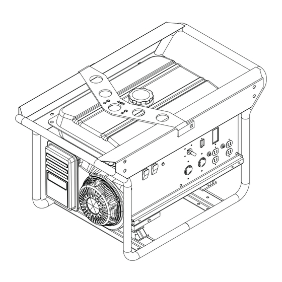
Page 8: Component Locations
COMPONENT LOCATIONS CENTRAL LIFTING EYE FUEL TANK FUEL LEVEL GAUGE CONTROL PANEL AIR FILTER HOUSING FUEL SHUT OFF VALVE (UNDER TANK) RECOIL STARTER HANDLE - ENGINE WHEEL KIT STARTING (OPTIONAL) BATTERY ENGINE CHOKE (UNDER TANK) BATTERY TRAY ENGINE (OPTIONAL) EXHAUST WHEEL KIT (OPTIONAL) -
Page 9: Control Panel Components
WARNING TEST BEFORE EACH USE SEE INSTRUCTIONS MPG 6000 ENGINE START SWITCH: This switch must be in the ON position to start the engine. To stop the engine, place switch in OFF position. AUTO IDLE SWITCH: When this switch is engaged, the engine speed will return to idle whenever the generator is not under load. -
Page 10: Grounding The Generator
GROUNDING THE GENERATOR The National Electrical Code (NEC) requires that the generator be properly connected to an approved ground source. The ground connection for this unit is located on the generator support leg. CONNECTING ELECTRICAL LOADS Allow the engine to warm-up before connecting any devices to the unit. -
Page 11: Wattage Consumption Of Equipment
WATTAGE CONSUMPTION OF EQUIPMENT DEVICE APPROXIMATE RUNNING WATTS Air Conditioner (12,000 BTU)** ........................... 1700 Air Conditioner (24,000 BTU)** ........................... 3800 Air Conditioner (40,000 BTU)** ........................... 6000 Battery Charger (20 Amp) ............................. 500 Belt Sander (3”) ..............................1000 Chain Saw ................................1200 Circular Saw (6-1/2”) .......................... -
Page 12: Extension Cord Selection Chart
EXTENSION CORD SELECTION CHART MAXIMUM CABLE LENGTH (FT) CURRENT LOAD IN VOLTS (AMPS) WATTS 1200 1800 2400 Keep extension cords as short as possible, preferably less than 15 feet long, to prevent voltage drop and possible overheating of wires. Use only high quality, well-insulated, three-wire, grounded cord sets to connect equipment to the generator. -
Page 13: Starting The Engine
STARTING THE ENGINE WARNING Never start or stop engine with electrical devices plugged into the receptacles OR with devices turned on, doing so may result in property damage, serious personal injury, or death. 1. Unplug all electrical loads from the unit’s receptacles before starting the engine. 2. -
Page 14: Stopping The Engine
STOPPING THE ENGINE 1. Shut off all loads and unplug electrical loads from the control panel receptacles. CAUTION NEVER start or stop the engine while electrical devices are plugged in and turned on, doing so may result in property damage or personal injury. 2. -
Page 15: Maintenance Schedule
MAINTENANCE SCHEDULE The following maintenance schedule should be followed to ensure proper performance of the unit. ITEM DAILY HRS. HRS. HRS. HRS. Visual walk around inspection Check engine oil level Check air filter Change engine oil Clean air filter Check and adjust spark plug Clean muffler/spark arrester Replace spark plug Check and adjust idle speed... -
Page 16: Unit Decals
"on" pour reconstituer la posición de "on" para restaurar energía del circuito. puissance de circuit. PN: 26560 Magnum Red Stripe - PG ENGINE SWITCH CHECK FUEL MAIN TURN FUEL MAIN... -
Page 17: Control Panel Assembly
CONTROL PANEL ASSEMBLY FRAME ITEM NO. PART NO. DESCRIPTION 26213 Panel, control - rear housing 24986R Panel, control 65888 Receptacle, 120V/20A duplex-black 65878 Module, auto idle 65487 Receptacle, 120V/30A twist (L5-30R) 65488 Receptacle, 240V/30A twist (L14-30R) 65886 Module, GFI sensing 27092 Breaker, 25A, 240V 26233... -
Page 18: Frame And Fuel Tank Assembly
FRAME AND FUEL TANK ASSEMBLY... - Page 19 ITEM NO. PART NO. DESCRIPTION 26123 Valve, fuel tank 26122 Gauge, fuel tank 28495 Cap, fuel tank 28494 Tank, fuel 60393 Screw, .250-20X1.000 hx hd 60243 Washer, flat .250 USS 24916B Weldment, frame 60144 Nut, .250-20 nylock 60690 Screw, .375-16X1.000 hx hd SS 60698 Washer, flat .375 SS 61120...
-
Page 20: Engine And Generator Assembly
ENGINE AND GENERATOR ASSEMBLY FRAME MUFFLER FRAME FRAME... - Page 21 ITEM NO. PART NO. DESCRIPTION 60028 Screw, .312-18X1.000 hx hd 60271 Washer, split lock .312 61147 Nut, .312-18 U-clip G5 ZY long type 24922R Muffler guard front 24954 Muffler 60119 Washer, .312 flat .875/.070 60020 Nut, M8-1.25 ser flg G8.8 lock 60358 Nut, .375-16 nylock G5 26114BH...
-
Page 22: Ac Wiring Diagram
AC WIRING DIAGRAM... -
Page 23: Dc Wiring Diagram
DC WIRING DIAGRAM... - Page 24 REV: ORG PART NO: 28922 02.04.09...
Need help?
Do you have a question about the MPG 6000 and is the answer not in the manual?
Questions and answers