Fantech VHR 704 Installation Manual
Heat recovery ventilator vhr series
Hide thumbs
Also See for VHR 704:
- Installation manual (40 pages) ,
- Operation manual (20 pages) ,
- Operation manual (28 pages)
Advertisement
Installation Manual
IMPORTANT - PLEASE READ THIS MANUAL
BEFORE INSTALLING UNIT
CAUTION -
Before installation, careful consideration must be given to how this system
will operate if connected to any other piece of mechanical equipment, i.e. a forced air furnace
or air handler, operating at a higher static. After installation, the compatibility of the two
pieces of equipment should be confirmed by measuring the airflow's of the Heat Recovery or
Energy Recovery Ventilators.
It is always important to assess how the operation of any HRV/ERV may interact with vented
combustion equipment (i.e. Gas Furnaces, Oil Furnaces, Wood Stoves, etc.).
NEVER -
install a ventilator in a situation where its normal operation, lack of operation or
partial failure may result in the backdrafting or improper functioning of vented combustion
equipment!!!
Your ventilation system should be installed in conformance with the appropriate provincial or state requirements
or in the absence of such requirements with the current edition of the National Building Code, and / or
ASHRAE's " Good Engineering Practices".
INSTALLATION, OPERATION AND MAINTENANCE MANUAL
VHR SERIES
VHR 704
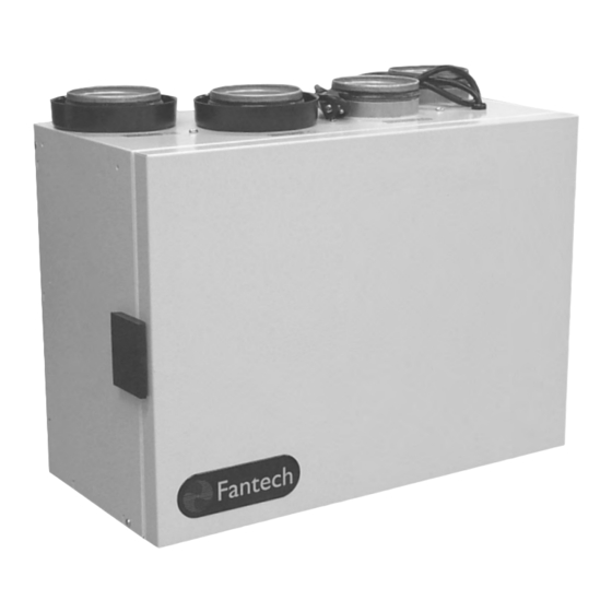
VHR 704
Heat Recovery Ventilator
1
Advertisement
Table of Contents

Related Manuals for Fantech VHR 704


Summary of Contents for Fantech VHR 704
- Page 1 VHR 704 Heat Recovery Ventilator Installation Manual IMPORTANT - PLEASE READ THIS MANUAL BEFORE INSTALLING UNIT CAUTION - Before installation, careful consideration must be given to how this system will operate if connected to any other piece of mechanical equipment, i.e. a forced air furnace or air handler, operating at a higher static.
-
Page 2: Table Of Contents
VHR 704 ........ -
Page 3: Vhr 704
4˝ 90˚ Elbow • CG 4 – 4˝ Adjustable Grille Distributed by: Fantech, reserves the right to modify, at any time and without notice, any or all of its products’ features, designs, components and specifications to maintain their technological leadership position. - Page 4 – – – – Specifications and Ratings • Model: VHR 704 • Insulated with 1" (25 mm) aluminum foil-face • Supply & exhaust ducts: 4˝ (100mm) • Total assembled weight: 26 lbs (12kg) high density polystyrene foam to prevent • Mounting: Wall bracket included •...
-
Page 5: Installation
Attach bracket to wall, lift unit defrost. (26 lbs (12 kg) VHR 704) & slide nuts into slots on bracket, tighten • Have a certain amount of heat screws to secure unit to bracket. - Page 6 INSTALLING DUCTS GOING TO / FROM OUTSIDE A well designed and installed ducting system will allow the HRV to operate at its maximum efficiency. Always try to keep PRACTICAL duct runs as short and straight as possible. See Installation Diagrams for installation examples. TIPS INSTALLING THE DUCTING •...
-
Page 7: Exhaust Air Ducting
Warning: The VHR 704 should be installed with a 4” (100mm) duct system that has less than 80 ft (25m) of equivalent duct length on the supply and on the exhaust side. If longer runs are required, increasing the duct diameter or following the instructions below might help. -
Page 8: Installation Examples
Fully Dedicated System (suggested for new construction) Stale air drawn from key areas of home (bathroom, kitchen, laundry) Fresh air supplied to main living areas NOTE* VHR 704 should be mounted with its duct connec- tions on top or similar. -
Page 9: Partially Dedicated System
If a release is required due to the furnace pulling too much air from the HRV/ERV, special care and attention is needed to its design. NOTE* VHR 704 should be mounted with its duct connec- tions on top or similar. -
Page 10: Air Flow Balancing
AIR FLOW BALANCING * Fantech’s superior design and use of EBM motors results in a steep fan curve that usually does not require balancing. Commissioning the system after installation is recommended which include confirming the proper operation of the system and how it interacts with other components within the home. -
Page 11: Heat Recovery Core
MAINTENANCE CAUTION MAKE SURE UNIT IS UNPLUGGED BEFORE ATTEMPTING ANY MAINTENANCE WORK The following components should also be inspected regularly and well maintained. PRACTICAL Filters need to be checked regularly TIPS • To prevent electrical shock, check FILTERS that the unit is unplugged before The filters (2) need to be checked and doing any repairs or maintenance. -
Page 12: Operation
The entire line of SHR/VHR series Heat Recovery Ventilators comes equipped with Fantech's new electronic uni-control board which offers a wide variety of features making it the ultimate ventilation control system. Fantech engineers have used the latest technology to provide solid, trouble free operation under any conditions. -
Page 13: Optional Remote Controls
OPERATION (CONT'D) OPTIONAL REMOTE CONTROLS * All controls are low voltage. 18 to 24 PRACTICAL gauge wire is recommended. TIPS Dehumidistat I - The wall mount dehumidistat monitors the humidity level in 2 wire installation the area it is installed. When the humidity level rises above the desired set- point, the HRV will activate to high speed/override mode. -
Page 14: Troubleshooting
TROUBLESHOOTING Problem Causes Solutions Air is too dry Dehumidistat control is set too low Increase the desired level of humidity. Change ventilation mode from continuous mode to standby. HRV out of balance Balance HRV Reduce the desired level of humidity. Combine this step with use of con- Dehumidistat control is set too high Air is too humid tinuous exchange mode. -
Page 15: Electrical Connections
ELECTRICAL CONNECTIONS... - Page 16 COOLING SYSTEM WIRE United States Canada Fantech, reserves the right to modify, at any time and without notice, any or all of its products’ features, designs, components and 1712 Northgate Blvd., 50 Kanalflakt Way, specifications to maintain their technological leadership position.
Need help?
Do you have a question about the VHR 704 and is the answer not in the manual?
Questions and answers