Table of Contents
Advertisement
Installation and operating instructions
SUPRAECO W
Heat pump
HP 270...
Please read the installation instructions before installing the appliance!
Please read the operating instructions before commissioning the appliance!
Please observe the safety instructions in the operating instructions!
The installation location must meet the requirements for sufficient ventilation!
Installation must only be carried out by an authorised contractor!
6720645393-00.1V
Advertisement
Table of Contents

Summary of Contents for Junkers SUPRAECO W HP 270
-
Page 1: Heat Pump
Installation and operating instructions SUPRAECO W Heat pump 6720645393-00.1V HP 270... Please read the installation instructions before installing the appliance! Please read the operating instructions before commissioning the appliance! Please observe the safety instructions in the operating instructions! The installation location must meet the requirements for sufficient ventilation! Installation must only be carried out by an authorised contractor! -
Page 2: Table Of Contents
Table of Contents Table of Contents „Operating“ menu ......19 Key to symbols and safety instructions ....3 8.3.1 „manual“... -
Page 3: Key To Symbols And Safety Instructions
Key to symbols and safety instructions Safety instructions Key to symbols and safety instructions Installation B Installation must only be carried out by an authorised contractor. Key to symbols B Do not install the appliance in the following locations: Warnings –... -
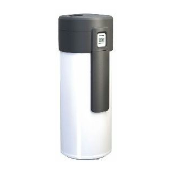
Page 4: Standard Delivery
Standard delivery Standard delivery 6720645393-03.3V Fig. 1 Heat pump Set of printed documents for the appliance SUPRAECO W – 6 720 646 161 (2012/04) -
Page 5: Information About The Appliance
Using the appliance for any other purpose will be considered incorrect Expansion vessel 12l 7 747 204 675 use. Junkers accepts no liability for any damage resulting from such use. Expansion vessel 18l 7 747 204 676 Expansion vessel 25l The appliance is not suitable for industrial applications. -
Page 6: Dimensions And Minimum Clearances
Information about the appliance Dimensions and minimum clearances 666.5 6720645393-05.2V Fig. 2 Appliance dimensions SUPRAECO W – 6 720 646 161 (2012/04) -
Page 7: Appliance Layout
Information about the appliance Appliance layout 11 12 6720645393-06.1V Fig. 3 Heat pump Cold water inlet - G1¼ “ Internal indirect coil outlet - G1“ Internal indirect coil inlet - G1" Sensor well for temperature sensor (data for programming unit for the solar thermal system or central heating) DHW circulation inlet - G3/4"... -
Page 8: Electrical Wiring Diagram
Information about the appliance Electrical wiring diagram 6720646160-20.1V Fig. 5 Temperature sensor for air inlet Storage tank temperature sensor for DHW Storage tank temperature sensor for cold water Power cable High-pressure pressure switch Capacitor for compressor Compressor Temperature controller for compressor Low-pressure pressure switch [10] DHW circulation pump [11] Air fan... -
Page 9: Refrigerant Circuit
Information about the appliance Refrigerant circuit The refrigerant circuit is a closed system in which the refrigerant R134a Then the heat is transferred via a heat exchanger, also referred to as a circulates as a heat transfer medium. condenser, to the storage tank water. The refrigerant R134a condenses in the process. -
Page 10: Safety, Control And Protective Devices
Information about the appliance 3.10 Safety, control and protective devices 3.10.1 High-pressure/low-pressure pressure switch The pressure switch protects the refrigerant circuit from overpressure. The pressure switch switches off the appliance in the event of overpressure. An automatic reset occurs as soon as the pressure in the refrigerant circuit has been regulated. -
Page 11: Specification
Information about the appliance 3.12 Specification Unit HP270...O... Operation Heating output (without electric heating insert) Performance coefficient (COP) – Heating output of integrated electric heating insert Air inlet 350/330 Air flow rate (without/with piping) Operating temperature °C ... +35 Compressor Refrigerant R134a Maximum pressure Domestic Hot Water... -
Page 12: System Scheme
Information about the appliance 3.13 System scheme 3.13.1 Heat pump for DHW heating with boiler support 6720646160-24.2V Fig. 7 Additional heating element (f.i. gas boiler) DHW circulation pump Cold water inlet Shut-off valve Check valve Safety valve Expansion vessel Drain set Heat pump [10] DHW connection [11] Outlet siphon... -
Page 13: Heat Pump For Dhw Heating With Solar Thermal System Support
Transport and storage 3.13.2 Heat pump for DHW heating with solar thermal system support 6720646160-28.2V Fig. 8 Thermal solar collectors NOTICE: Transport damage! Solar programming unit B To avoid transport damage, wait until the appliance is Cold water inlet at the installation location to remove the protective Shut-off valve packaging. -
Page 14: Installation
Installation • The plinth of the appliance must be strong enough (the appliance weighs about 400 kg when the storage tank is filled, with the weight distributed equally over its 3 adjustable feet). To ensure faultless operation and easy access to all components and connections for maintenance and repairs, maintain the minimum clearances specified in Fig. -
Page 15: Installing The Air Ducts
Installation Installing the air ducts Inlet air can be taken from the room where the appliance is installed, C1 C2 from another room or from the outside. In the last two cases, ducts must be assembled in the air inlet. To ensure maximum appliance performance and avoid condensation in the outer ducts surface, use thermally and acoustically insulated ducts. -
Page 16: Connection For The Internal Indirect Coil
Installation To avoid heat loss and improve appliance efficiency: B Insulate all water connections. Safety valve B Install a safety valve at the appliance's cold water inlet. If the water inlet pressure is higher than 8 bar - 80% the allowable maximum value (10 bar) -, install a check valve. -
Page 17: Water Characterisitcs
Electrical Connections B Reopen purge valve for a few seconds to assure the complete purge of Check if the purge valve outlet is downwards oriented. If the system.. not: B Rotate circulation pump speed selector to position „I“. B Rotate the purge valve clockwise (tightening) to assure that the outlet is downwards oriented. -
Page 18: Appliance's Electrical Connection
Commissioning NOTICE: Operation Fuse protection! B The wiring diagram must show a separate connection for the appliance.There must be a 30 mA RCD and earth conductor. The appliance is already equipped with a cable for the power supply. Power is supplied via the connecting cable (2 m) and an earthed wall menu socket (230 V AC/50 Hz). -
Page 19: Operating" Menu
Operation „Operating“ menu "Full" mode activation reduces device efficiency, and Access the „Operating“ menu should only be selected in the event of need for a rapid B Press the „menu“ key for no longer than 3 seconds. increase in water temperature. menu <... -
Page 20: Main" Menu
Operation B Press the „+“ or „-“ keys until the desired value is reached. 6720646160-19.1V Fig. 25 „Mode“ function 6720646160-13.1V Fig. 23 Setting the temperature „Electrical“ mode B Press the „ok“ key to confirm the selection. In this mode, the only heat source used is electrical power. The selected temperature will blink 3x to signal confirmation. -
Page 21: Prog" Function - Timetable Operation Programming
Operation „P2“ and „P3“ periods The heat pump functions at times preset by the user. 6720646160-09.1V Fig. 28 „Combi“ mode This mode permits setting the water temperature anywhere between 6720646160-35.1V 30 °C and 70 °C. Fig. 31 „P2“ and „P3“ periods Setting the operating periods to „P2“... -
Page 22: Leg" Function - Automatic Thermal Disinfection
Operation B Use the „+“ and „-“ keys to define the operating start schedule of the period. B Press „ok“. Blinking display shows the operating stop schedule for the 2 period. B Use the „+“ and „-“ keys to define the operating duration. B Press „ok“. -
Page 23: Set" Function - Adjustments
Operation Upon reaching a temperature of 70 °C, the device returns to the „reset“ consumption previously selected mode. Displays with indication of cumulative consumption. B Press „-“. The disinfection process will not be repeated until it is Displays with blinking „del“ indication. reactivated. -
Page 24: Factory Configurations
Operation Factory configurations B Confirm the selection using the „ok“ key. The clock is set and the day of the week begins to blink. Upon definition of the temperature units and timetable, the device will operate according to the factory set values. Heating mode: „Combi“... -
Page 25: Controls
Environment / disposal 8.10 Controls menu manual < 3 s Full menu Mode Prog > 3 s Purg Info menu > 3 s 6720646160-47.3V Used appliances Environment / disposal Used appliances contain valuable materials that should be recycled. The various assemblies can be easily dismantled and synthetic materials Environmental protection is a fundamental corporate strategy of the are marked accordingly. -
Page 26: Maintenance
Maintenance Maintenance B Remove magnesium anode. DANGER: Risk of electric shock! B Isolate the appliance from the power supply using the fuse or another protective device before carrying out any work on electrical parts. 10.1 General inspections Inspect the appliance regularly to identify possible malfunctions. B Keep the appliance's casing the installation location clean. -
Page 27: Refrigerant Circuit
Maintenance 10.7 Refrigerant circuit NOTICE: Refrigerant leak! B Repairs to the refrigerant circuit (e.g. to the compressor, condenser, evaporator, expansion vessel) may only be carried out by an authorised contractor. 10.8 High limit safety cut-out The appliance is equipped with an automatic safety facility. This safety facility isolates the DHW storage tank from the power supply to prevent the risk of injury if the DHW storage tank water temperature rises above a certain limit. -
Page 28: Display
Automatic stop of „Heat pump“ mode when air inlet temperature is lower than 5 °C or higher than 35 °C COLD Temperature of the inlet air ≤ +5 °C Table 11 Display indications Bosch Thermotechnik GmbH Junkersstrasse 20-24 D-73249 Wernau www.junkers.com...
Need help?
Do you have a question about the SUPRAECO W HP 270 and is the answer not in the manual?
Questions and answers