Table of Contents
Advertisement
Section
INST
INST
ALLA
ALLA
INST
INSTALLA
INST
ALLA
ALLATION and OPERA
GAS-FIRED INFRA-RED RADIANT TUBE HEATERS
WARNING:
MENT, ALTERATION, SERVICE OR MAINTENANCE CAN
CAUSE PROPERTY DAMAGE, INJURY OR DEATH. READ
THE INSTALLATION, OPERATING AND MAINTENANCE
INSTRUCTIONS THOROUGHLY BEFORE INSTALLING
OR SERVICING THE EQUIPMENT
Enerco Technical Products, Inc.
TION and OPERA
TION and OPERA
TION and OPERA
TION and OPERATING INSTR
IMPROPER INSTALLATION, ADJUST-
4560 W.160th St.
Cleveland, Ohio 44135
Phone: 800-251-0001
TING INSTR
TING INSTR
TING INSTR
TING INSTRUCTIONS
f f f f f or
or
or
or
or
PLACE NEAR HEATING UNIT
UCTIONS
UCTIONS
UCTIONS
UCTIONS
ANSI Z83.20b-2004
CSA 2.34b-2004
MOST RECENT EDITION
MODELS
ERXL-60,
ERXL-80
ERXL-80S,
ERXL-100
ERXL-100S,
ERXL-125
ERXL-125S
ERXL-150
ERXL-150L,
ERXL-175
ERXL-175L
Stock No. 18677XL 8/05 Rev. A
18677
Rev. A 8/05
Advertisement
Table of Contents
Troubleshooting

Related Manuals for Enerco ERXL-60


Summary of Contents for Enerco ERXL-60
- Page 1 CAUSE PROPERTY DAMAGE, INJURY OR DEATH. READ THE INSTALLATION, OPERATING AND MAINTENANCE INSTRUCTIONS THOROUGHLY BEFORE INSTALLING OR SERVICING THE EQUIPMENT 4560 W.160th St. Cleveland, Ohio 44135 Phone: 800-251-0001 Enerco Technical Products, Inc. Stock No. 18677XL 8/05 Rev. A 18677 Rev. A 8/05...
- Page 2 Section 18677 Rev. A 8/05...
- Page 3 (1) year warranty or applicable warranties of the suppliers. The sole responsibility of ENERCO under this warranty shall be to replace or repair any part for which a written claim is made to ENERCO within the time limit of the warranty, which is returned upon request to ENERCO -- F.O.B.
- Page 4 Section Warnings WARNING FAILURE TO FOLLOW THESE INSTRUCTIONS CAN CAUSE PROPERTY DAMAGE, SEVERE INJURY OR DEATH: FIRE OR EXPLOSION HAZARD: Combustibles Failure to maintain the specific minimum clearances to combustibles could result in a serious fire hazard. Do not locate flammable or combus- tible materials within this distance.
- Page 5 Section Warnings IMPORTANT FAILURE TO FOLLOW THESE INSTRUCTIONS CAN CAUSE PROPERTY DAMAGE OR PERSONAL INJURY Do not use in an atmosphere containing halogenerated hydrocarbons or other corrosive chemicals. Some compounds in the air can be drawn into the equipment and can cause an accelerated rate of corrosion of some parts of the heat exchanger.
-
Page 6: Table Of Contents
Section TABLE OF CONTENTS WARNINGS & WARRANTY Read this sections carefully. Improper installation adjustment, operation or mainte- nance can cause property damage, injury or death INDEX INTRODUCTION Checking Shipment - Installer Responsibility 6-14 INSTALLATION: Planning National codes - Critical Considerations - Installation Procedure Accessory parts Lists - Clearances to Combustibles - Parts list for packaged Ener-Radiant III Heaters 15-20... -
Page 7: Introduction
All heaters and associated gas piping should be installed in accordance with applicable specifications and this installation made only by firms (or individuals) well qualified in this type of work. Consult local building inspectors, Fire Marshals or your local ENERCO Representative for guidance. -
Page 8: National Standards And Applicable Codes
Section Planning PLANNING Section 3 The following codes and instructions should be followed when planning the installation of the Ener-Radiant XL heater. In addition to these instructions, the warnings in (Section 1 ) must be carefully adhered to since improper installation may lead to property damage, injury or death. - Page 9 Section Planning Critical Considerations Ener-Radiant XL is a suspended heater. Therefore, its stability, flexibility, and safety are very important. Before starting installation, be sure the system can meet the following requirements. • Maintain specified clearances to combustibles, and safe distance from heat-sensitive material, equipment and work stations.
- Page 10 Section Planning ACCESSORY PARTS LIST Stock Number Description 10371 Thermostat 24 volt 10392 Thermostat 120 volt 17370 Chain Kit 03445 Turbulator 10’ Section 03447 Turbulator 5’ Section 16401 24” Stainless Steel Flexible Gas Connector 18677A Installation Manual / ER3LSeries F106414 U-Tube Accessory Kit F106415 Elbow Accessory Kit...
-
Page 11: Clearances To Combustibles
Section Planning Clearances To Combustibles TABLE 1: Minimum Clearances to Combustibles (Use figure 1 on page 10 as a Guide) Refelctor Type Position ERXL-60 ERXL-80 ERXL-100 ERXL-125 ERXL-150 ERXL-175 Standard Reflector 6” 6” 6” 6” 6” 8” (Horizontal) 30” 36”... - Page 12 Section Planning Clearances To Combustibles FIGURE1: Clearances to Combustibles (Refer to Table 1 on page 9) Standard Reflector Reflector Tilt “U”-Tube, Standard “U”-Tube, Opposite 45 “U”-Tube, Full 45 Front and Back Clearance 18677 Rev. A 8/05...
- Page 13 ERXL-80S, LP COMP / 20’ F107414XL ERXL-100S, NG COMP /30’ F107415XL ERXL-100S, LP COMP / 30’ F102650XL ERXL-60 NG / BRN & Cont Box F102651XL ERXL-60 LP / BRN & Cont Box F102652XL ERXL-80S, ER3-80 NG /BRN & Cont & Box F102653XL ERXL-80S, ER3-80 LP / BRN &...
- Page 14 Section Planning Figure “A” - Assembly Model ERXL-60, ERXL-80S Figure “B” - Assembly Model ERXL-80 Figure “C” - Assembly Model ERXL-100S See Page 11 for PARTS LIST 18677 Rev. A 8/05...
- Page 15 Section Planning Parts List for Packaged Ener-Radiant XL Tube Heaters ITEM STOCK DESCRIPTION NUMBER REQUIRED F107404XL ERXL-100 NG COMP / 40’ F107405XL ERXL-100 LP COMP / 40’ F107406XL ERXL-125 NG COMP / 50’ F107407XL ERXL-125 LP COMP / 50’ F107408XL ERXL-150, NG COMP / 50’ F107409XL ERXL-150, LP COMP / 50’...
- Page 16 Section Planning Figure “D” - Assembly Model ERXL-100, ERXL-125S Figure “E” - Assembly Model ERXL-125, ERXL-150, ERXL-175 Figure “F” - Assembly Model ERXL-150L, 175L See Page 13 for PARTS LIST 18677 Rev. A 8/05...
-
Page 17: Installation: Assembly
Section 4 FIGURE 2: Ener-Radiant XL Overview Key FIGURE 2a: Ener-Radiant XL Model ERXL-60, ERXL-80S, Assembly Overview 20 ft. Exchanger length. 21 ft. - 4 in. Total Heater length. 4 Suspension points as indicated FIGURE 2b: Ener-Radiant XL Model ERXL-80, Assembly Overview 30 ft. - Page 18 Section 4 Installation & Assembly Section FIGURE 2c: Ener-Radiant XL Model ERXL-100S, Assembly Overview 30 ft. Exchanger length. 31 ft - 4 in. Total Heater length. 6 Suspension points as indicated. FIGURE 2d: Ener-Radiant XL Model ERXL-100, ERXL-125S 40 ft. Exchanger length. 41 ft - 4 in. Total Heater length. 8 Suspension points as indicated. FIGURE 2e: Ener-Radiant XL Model ERXL-125, ERXL-150, ERXL-175 50 ft.
- Page 19 Section Installation & Assembly Assemble the heater components as shown in Figures 2a, 2b, 2c, 2d, 2e and 2f. Optional reflector configurations are shown in (Figure 1). Install appropriate suspension hardware, beam clamps, chain or rod at predetermined locations. Adjustment of chain length will provide uniform pitch. Couplings: Tube and tube fittings are connected by wrap-around couplings which clamp by means of a tapered, hammer-driven lock member.
- Page 20 Section 4 Installation & Assembly Section FIGURE 4: Installation of Elbow & Coupling (optional equipment) Elbow package: Stk. #F106415 Elbow Pacakge includes: (1) elbow and (1) coupling. Install elbow into radiant tube sequence where plans indicate a 90 bend (see Figure 4). Elbow Elbow Fitting Dimensions Stk #F106414 U-Tube Package includes:...
- Page 21 Section Installation & Assembly FIGURE 5: Typical Suspension Details Chain Kit - Stk #17370 One chain kit will suspend one 10 ft. section of tube and one 10 ft. section of reflector. FIGURE 6: Tube & reflector Hanger 18677 Rev. A 8/05...
- Page 22 Section 4 Section Installation & Assembly FIGURE 7: Mounting Flange / Tube Detail 1) Insert tube 06413 into front casting to point (A). 2) Tighten set screws marked (B) until snug. 3) After both set srews are sung, turn each additional 1/4 turn to secure tube in place.
-
Page 23: Installation: Venting & Ducting
Section Vent / Ducting VENTING / DUCTING Section 5 General Requirements Heater must be vented in accordance with specification ANSI Z223.1 - latest revision. Partial information relating to this specification is provided in this section with regard to size and configurations for venting arrangements ( see Figures 12, 13, 14, 15, 16). - Page 24 In combustible or noncombustible walls, use Tjerland VH1-4” (Stk #19022). Follow vent manufacturer’s instructions for proper installation. (Alternative vent Enerco Stk. #19023) b) Four (4”) inch O.D. flue pipe is required. Thirty (30’) feet maximum length is recommended. Up to forty-five (45’) feet maximum may be used if insulated to prevent excess condensation.
-
Page 25: Unvented Operation
Section Vent / Ducting FIGURE 12: Unvented Operation 1) Ventilation equal to 4 CFM per 1,000 BTU/hr. firing rate must be provided in unvented heater installations. 2) For dimensions A “unvented” refer to (Figure 1 -- Minimum Clearances to Combustibles). FIGURE 13b: Double Wall FIGURE 13a: Single Wall Single wall vent run... - Page 26 Section Section 5 Venting / Ducting FIGURE 14: Vertical Venting THIS SPACE IS INTENTIONALLY BLANK 18677 Rev. A 8/05...
- Page 27 H = 6 ft. H = 8 ft. H = 15ft. Model# H = 6 ft. H = 8 ft. H = 15ft. ERXL-60 D = 7” D = 6” D = 6” ERXL-60 D = 10” D = 10”...
- Page 28 FIGURE 16: Non-Pressurized Outside Air Supply Duct Outside Air Terminal: Use ACME #104 Enerco Stk. #19030 PCV Pipe, “Dryer Hose”, or equivalent may be used instead of standard vent pipe 18677 Rev. A 8/05...
-
Page 29: Installation: Gas Piping 6
Section Gas Piping GAS PIPING Section 6 Read applicable warnings in (Section 1) before proceeding with Gas Pipe installation. Improper installation may result in property damage, severe injury or death. Meter and service must be large enough to handle all the burners being installed plus any other connected load. - Page 30 Section Wiring WIRING Section 7 Heaters are normally controlled by thermostats. Line voltage thermostats are wired directly ( see Feigure 18a), the recommended 24V thermostats use a relay (see Figure 18b). Heaters must be grounded in accordance with the National Electrical Code ANSI/NFPA-70 - latest revision. Heaters may also be controlled with a manual line voltage switch or timer switch in place of the thermostat.
- Page 31 Section Wiring FIGURE 19: Wiring of Low Voltage Thermostat and Relay When usung 1 - 2 burners, use SPDT Transformer Relay / Stk. #00172 When using 3 - 4 burners, use DPDT Transformer Relay / Stk. #00183 Wires marked with an asterisk (*) are for use only with the DPDT Transformer Relay.
- Page 32 Section Wiring FIGURE 20: Ener-Radiant XL Burner Internal Wiring • If any of the original wire as supplied with the appliance must be replaced, it must be replaced with wiring material having a temperature rating of at least 105 C and 600 volts. •...
- Page 33 Section Wiring FIGURE 21: Ener-Radiant XL Burner Internal Wiring Ladder Diagram 18677 Rev. A 8/05...
-
Page 34: Operation/Maintenance
Section 8 Section Operation & Maintenance OPERATION & MAINTENANCE Section 8 Sequence of Operation 1. Turn the thermostat up. When the thermostat calls for heat, blower motor will energize. 2. When the motor approaches nominal running RPM, the air proving switch closes and activates the ignition module. -
Page 35: Troubleshooting
Section Operation & Maintenance Troubleshooting CAUTION: Before opening the Ener-Radiant XL burner door for any type of service, be sure the gas supply has been shut off at the heater and the electrical cord from the burner box has been unplugged. 1. -
Page 36: Operation - Maintenance - Troubleshooting
Section Section 8 Operation & Maintenance Honeywell Valve LED Status The ENER-Radiant XL series Tube Heater is equipped with a honeywell Smart Valve. This valve has a built-in diagnostic program, which will assist in troubleshooting in the event of a valve-related problem. The LED or (Light Emitting Diode) is located on the top of the valve as shown in diagram below. - Page 37 Section Operation & Maintenance 18677 Rev. A 8/05...
- Page 38 Section 8 Section Operation & Maintenance 18677 Rev. A 8/05...
- Page 39 Section 9 Item Part Number Description 02731 Hot Surface Igniter 02730 Flame Sensor 10413A Air Sensing Switch (ERXL-60, 80, 100, 125) 10414A Air Sensing Switch (ERXL-150, 175) 01391A Door Switch 02371 Burner Cup Assembly 07376 Motor and Blower Assembly 17376...
-
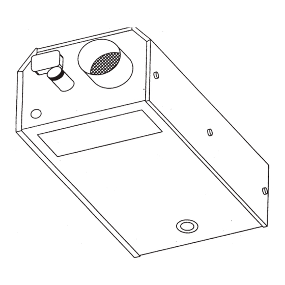
Page 40: Appendices
Section Appendices FIGURE 24: Ener-Radiant XL Burner & Control Housing 18677 Rev. A 8/05... - Page 41 1. Burners shall be capable of firing with one of the fuel options as specified on the purchase documents: Natural Gas or LP. 2 Burners shall be supplied to fire at any one of the input rates as specified. ERXL-60 60,00 BTU/hr ERXL-125...
-
Page 42: General Specifications
Burner Ratings and Heat Exchanger Lenghts (Natural an LP) LP Gas: 10.5” W.C. Model# Rate (BTU/hr.) Heat Exchanger Length Turbulator 1/2” NPT Gas Connector Size ERXL-60 60,000 20 ft. 10 ft. Gas INLET pressure ERXL-80S 80,000 20 ft. 10 ft. - Page 43 Section 18677 Rev. A 8/05...
- Page 44 Section Enerco Technical Products, Inc. 4560 W.160th St.Cleveland, Ohio 44135 Phone: 800-251-0001 www.enerco.com 18677 Rev. A 8/05...
Need help?
Do you have a question about the ERXL-60 and is the answer not in the manual?
Questions and answers