Table of Contents
Advertisement
Quick Links
- 1 Kit Contents
- 2 System's Configuration
- 3 Installation Procedure (System's Component Locations, Electrical Connections)
- 4 Active Functionalities (Descriptions)
- 5 How to Program Functionalities, Cobra Remote Controls and Driver Cards Self Learning Procedure (See 'Page 1' and 'Page 2' of the Functions Programming Tables Manual)
- Download this manual
Advertisement
Table of Contents

Related Manuals for Cobra 4600 CAN/PLIP


Summary of Contents for Cobra 4600 CAN/PLIP
- Page 1 4600 CAN/PLIP INSTALLATION MANUAL...
-
Page 2: Table Of Contents
- ELECTRIC DIAGRAMS 7. PROGRAMMABLE FUNCTIONS (see the “Functions programming tables” manual) .........17 8. HOW TO PROGRAM FUNCTIONALITIES, COBRA REMOTE CONTROLS AND DRIVER CARDS SELF LEARNING PROCEDURE (see ‘PAGE 1’ and ‘PAGE 2’ of the “Functions programming tables” manual) ....17 9. -
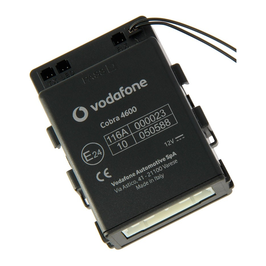
Page 3: Kit Contents
HOW TO DEFINE THE INSTALLATION SOLUTION. Access to the web site www.cobra-at.com > Login > user ID > password > access > professional area and, clicking on the menu, supply all the requested destination vehicle information (in the example a VW Polo, year 2011) as the information of the product to install, in this case the 4600 range. -
Page 4: System's Configuration
Wait until the programming confi rmation window appears. Additional software installation and tool usage details are available on the specifi c manual supplied in the Data Linker kit or in the Cobra web site, professional area, Application manuals. INSTALLATION MANUAL 4600 CAN/PLIP... -
Page 5: How To Prepare Pin Code Card
The RF antennas positioning (for both the main unit and the siren) is crucial for a proper system’s performance. They must not be cut, wrapped, connected to any other cables or to the vehicle body and they must be kept separate from the main wiring harness and as far as possible from metallic parts. INSTALLATION MANUAL 4600 CAN/PLIP... -
Page 6: Electrical Connections
Pay attention when joining two or more wires. Avoid to make “quick connections” that do not ensure a good quality. Also make sure that the wires of the Cobra 4600 are routed so that they follow the original wiring of the vehicle to which they should be joined with the raps. - Page 7 J-22 Analogic input: make the connection if required by the specifi c vehicle CAN installation sheet. J-23 Negative input for additional modules: to be used as a triggering input for the connection of compatible Cobra modules. J-24 Analogic output: to be used for the function described in step 7.17 or 7.20.
-
Page 8: Active Functionalities (Descriptions)
J-22 Positive perimetric input: to be connected to the vehicle roof lamp. The input is 7 s delayed after the system arming. J-23 Negative input for additional modules: to be used as a triggering input for the connection of compatible Cobra modules. -
Page 9: Wiring Scheme
4600 Art. (NO WIRELESS SIREN) See diagram "H" THE FUSES IN THE DIAGRAM ARE NOT SUPPLIED YELLOW-BLUE COBRA BUS BLACK J-15 15 A STARTER +50 GREEN J-14 max 20A (1 sec.) GREEN 6A cont. POWER POWER 7,5 A WHITE BLINKER... - Page 10 4600 Art. (WIRELESS SIREN) THE FUSES IN THE DIAGRAM ARE NOT SUPPLIED POWER POWER 7,5 A BLINKER YELLOW OUTPUT BLUE See paragraph 11 POWER YELLOW-BLUE 7,5 A COBRA BUS YELLOW-GREEN BLINKER OUTPUT BLINKER LOGIC LOGIC ORANGE VIOLET BLINKER YELLOW-WHITE CAN - L OUTPUT...
- Page 11 NO WIRELESS SIREN CONNECTIONS BONNET PUSH-BUTTON See the BLACK BLUE J-21 vechicle fitting YELLOW-BLUE YELLOW-BLUE instructions Ø 10 mm 14 mm BLACK Ø 10 mm Ø 2 mm BLACK LED PANEL WIRELESS SIREN CONNECTIONS See the vechicle fitting instructions Antenna BLUE Ø...
- Page 12 WHITE wire J 17 WHITE wire J 17 - / + U.S. U.S. 30 86 85 BLACK - / + RED (TX) Antenna WHITE BLACK (RX) Original relay controlled by a negative signal. Install the jumper wire (see the catalogue) U.S.
-
Page 13: How To Program Functionalities, Cobra Remote Controls And Driver Cards Self Learning Procedure (See 'Page 1' And 'Page 2' Of The "Functions Programming Tables" Manual)
FUNCTIONS. (see the “FUNCTIONS PROGRAMMING TABLES” manual). 8 - HOW TO PROGRAM FUNCTIONALITIES, COBRA REMOTE CONTROLS AND DRIVER CARDS SELF LEARNING PROCEDURE. IMPORTANT: (only for PLIP applications and just after the power supply connection or when the battery has been disconnected and reconnected). -
Page 14: Functional Test
G. Turn the ignition key OFF and disconnect the BLU wires of the main unit and of the siren from GND (if grounded through the additional pushbutton simply open the bonnet). Check the system functionality arming the system and triggering the alarm to check the proper sounding of the siren. INSTALLATION MANUAL 4600 CAN/PLIP... -
Page 15: Documents Handover
- Central dimensions 91x69x35 mm - Siren dimensions 113x79x45 mm Trasmitter battery / Cobra Driver Card Lithium Battery 3 V CR2032 14. - FOR MARKET ONLY Category 1,2 or 2-1 systems permanently installed as aftermarket equipment by import or distribution centres, vehicle dealers, or by Independent Installers, shall be installed by companies and technicians who are trained, qualifi... - Page 16 Cobra Automotive Technologies via Astico 41 - 21100 VARESE - ITALY www.cobra-at.com 06DE3325C - 06/12...
Need help?
Do you have a question about the 4600 CAN/PLIP and is the answer not in the manual?
Questions and answers
Доброго дня. Не знайшов в інструкції яким чином можна змінити пін код який вводиться за допомогою кнопок на пульті керування імобілайзера. Допоможіть будь ласка.