Table of Contents
Advertisement
Advertisement
Table of Contents

Related Manuals for Cobra 4627 CAN/PLIP


Summary of Contents for Cobra 4627 CAN/PLIP
- Page 1 4625 - 4627 CAN/PLIP INSTALLATION MANUAL...
-
Page 2: Table Of Contents
- ELECTRIC DIAGRAMS 7. PROGRAMMABLE FUNCTIONS (see the “Functions programming tables” manual) .........13 8. HOW TO PROGRAM FUNCTIONALITIES, COBRA REMOTE CONTROLS AND DRIVER CARDS SELF LEARNING PROCEDURE (see ‘PAGE 1’ and ‘PAGE 2’ of the “Functions programming tables” manual) ....13 9. -
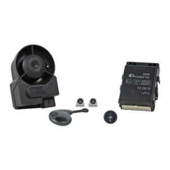
Page 3: Kit Contents
HOW TO DEFINE THE INSTALLATION SOLUTION. Access to the web site www.cobra-at.com > Login > user ID > password > access > professional area and, clicking on the menu, supply all the requested destination vehicle information (in the example a VW Polo, year 2011) as the information of the product to install, in this case the 4600 range. -
Page 4: System's Configuration
Wait until the programming confi rmation window appears. Additional software installation and tool usage details are available on the specifi c manual supplied in the Data Linker kit or in the Cobra web site, professional area, Application manuals. INSTALLATION MANUAL 4625 - 4627 CAN/PLIP... -
Page 5: How To Prepare Pin Code Card
The RF antennas positioning (for both the main unit and the siren) is crucial for a proper system’s performance. They must not be cut, wrapped, connected to any other cables or to the vehicle body and they must be kept separate from the main wiring harness and as far as possible from metallic parts. INSTALLATION MANUAL 4625 - 4627 CAN/PLIP... - Page 6 Pay attention when joining two or more wires. Avoid to make “quick connections” that do not ensure a good quality. Also make sure that the wires of the Cobra 4625 - 4627 are routed so that they follow the original wiring of the vehicle to which they should be joined with the raps.
- Page 7 THE FUSES IN THE DIAGRAM ARE NOT SUPPLIED chapter 11 BLACK J-17 BLUE 15 A STARTER +50 J-21 GREEN POWER max 20A (1 sec.) 7,5 A J-22 GREEN J-20 BLINKER YELLOW-WHITE 6A cont. OUTPUT POWER J-12 ORANGE ORANGE CAN - H 7,5 A J-11 J-19...
-
Page 8: Active Functionalities (Descriptions)
J 15 J 15 - / + U.S. U.S. 30 86 85 BLACK RED (TX) - / + Antenna WHITE BLACK (RX) Original relay controlled by a negative signal. Install the jumper wire (see the catalogue) U.S. sensors, led panel Vehicle horn connection with negative control between the Ultrasound TX and RX, if you don't and antenna connections. - Page 9 SIREN CONNECTIONS NO WIRELESS BONNET PUSH-BUTTON J-17 BLACK B L U E J-10 Ø 10 mm YELLOW-BLUE YELLOW-BLUE 14 mm See the vehicle fitting instructions Ø 10 mm BLACK Ø 2 mm BLACK WIRELESS SIREN CONNECTIONS LED PANEL See the vehicle fitting instructions Antenna BLUE...
- Page 11 J-11 and J-12 Do not connect. J-13 Negative input for additional modules: to be used as a triggering input for the connection of compatible Cobra modules. J-14 Negative output for modules: active when the system is armed. To be used for the connection of compatible Cobra modules.
- Page 12 Cobra remote control (optional) - (see electrical diagram F). J-24 CDL unlock negative output (only for 4627): low power control signal to unlock central door locking. Activated by the Cobra remote control (optional) - (see electrical diagram F). MAKE CONNECTIONS AS FOR ELECTRIC DIAGRAMS 6.
-
Page 13: Programmable Functions (See The "Functions Programming Tables" Manual)
FUNCTIONS. (see the “FUNCTIONS PROGRAMMING TABLES” manual). 8 - HOW TO PROGRAM FUNCTIONALITIES, COBRA REMOTE CONTROLS AND DRIVER CARDS (optional) SELF LEARNING PROCEDURE. IMPORTANT: (only for PLIP applications and just after the power supply connection or when the battery has been disconnected and reconnected). -
Page 14: Functional Test
G. Turn the ignition key OFF and disconnect the BLU wires of the main unit and of the siren from GND (if grounded through the additional pushbutton simply open the bonnet). Check the system functionality arming the system and triggering the alarm to check the proper sounding of the siren. INSTALLATION MANUAL 4625 - 4627 CAN/PLIP... -
Page 15: Documents Handover
To ensure consumers insurance cover is not adversely effected it is highly recommended that all installations are carried out by Thatcham recognised installers and that all installs are registered providing the vehicle owner with a Thatcham recognition of installation for presentation to insurers. INSTALLATION MANUAL 4625 - 4627 CAN/PLIP... - Page 16 Cobra Automotive Technologies via Astico 41 - 21100 VARESE - ITALY www.cobra-at.com 06DE3630B - 11/12...
Need help?
Do you have a question about the 4627 CAN/PLIP and is the answer not in the manual?
Questions and answers